LARGE FORMAT CNC


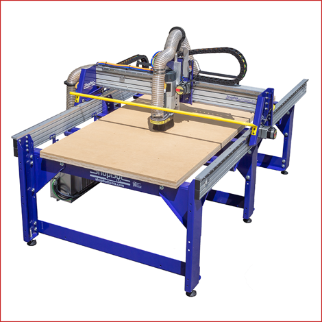
This week we were introduced to the CNC machine, we created our own designs and cut them using the machine.


What is CNC?


CNC stands for Computerized Numerical Control. It is a computerized manufacturing process in which pre-programmed software and code controls the movement of production equipment. CNC machining controls a range of complex machinery, such as grinders, lathes, and turning mills, all of which are used to cut, shape, and create different parts and prototypes.


How does it work?


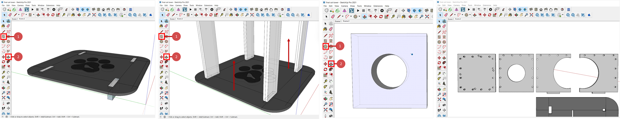
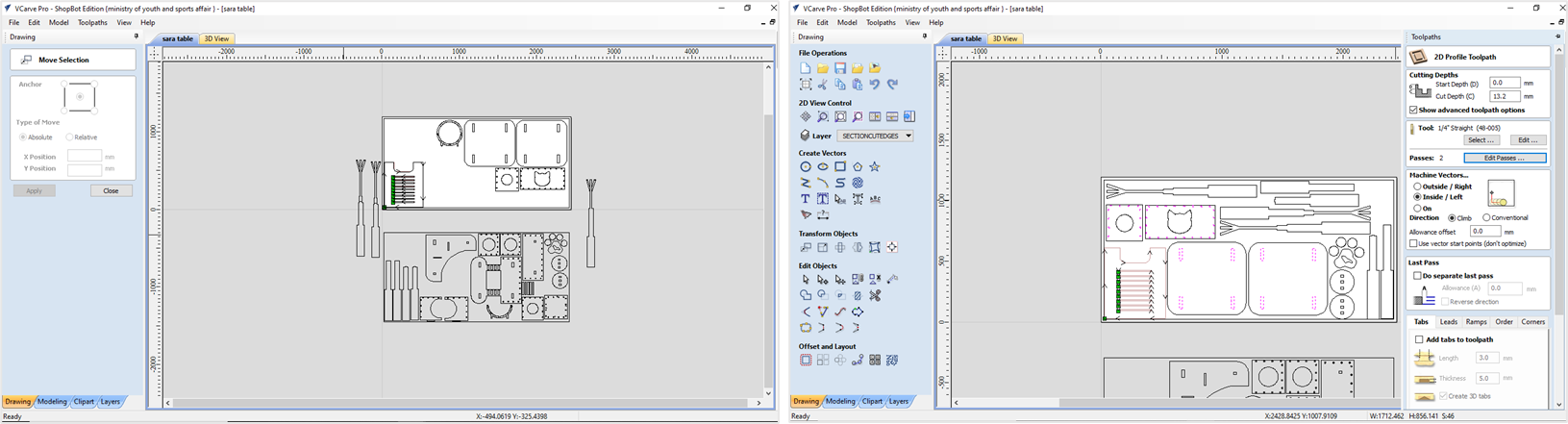
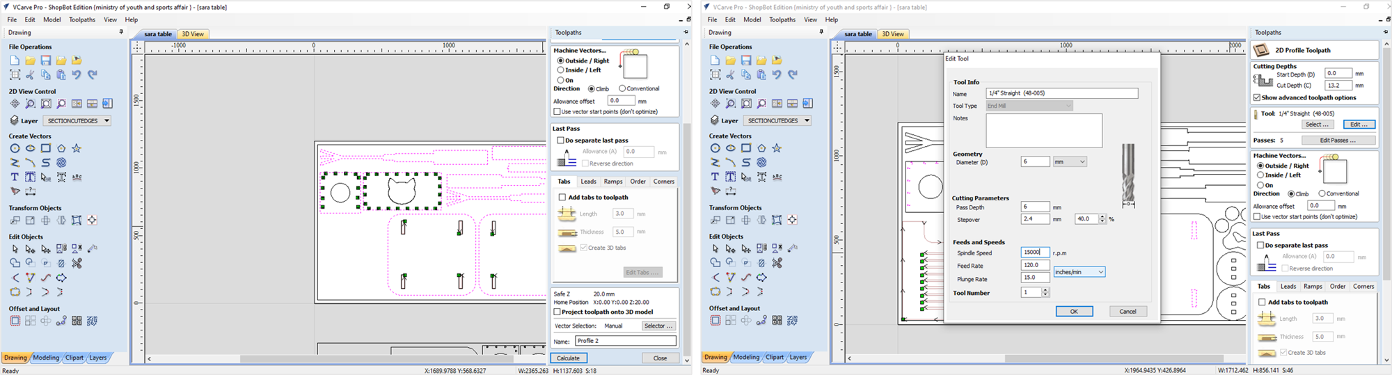
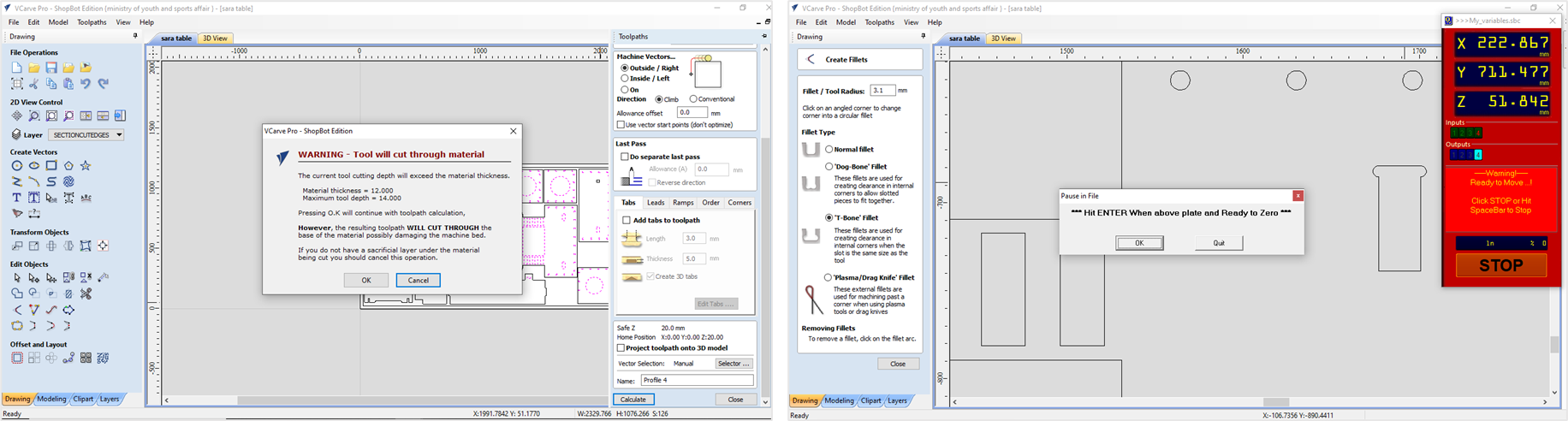
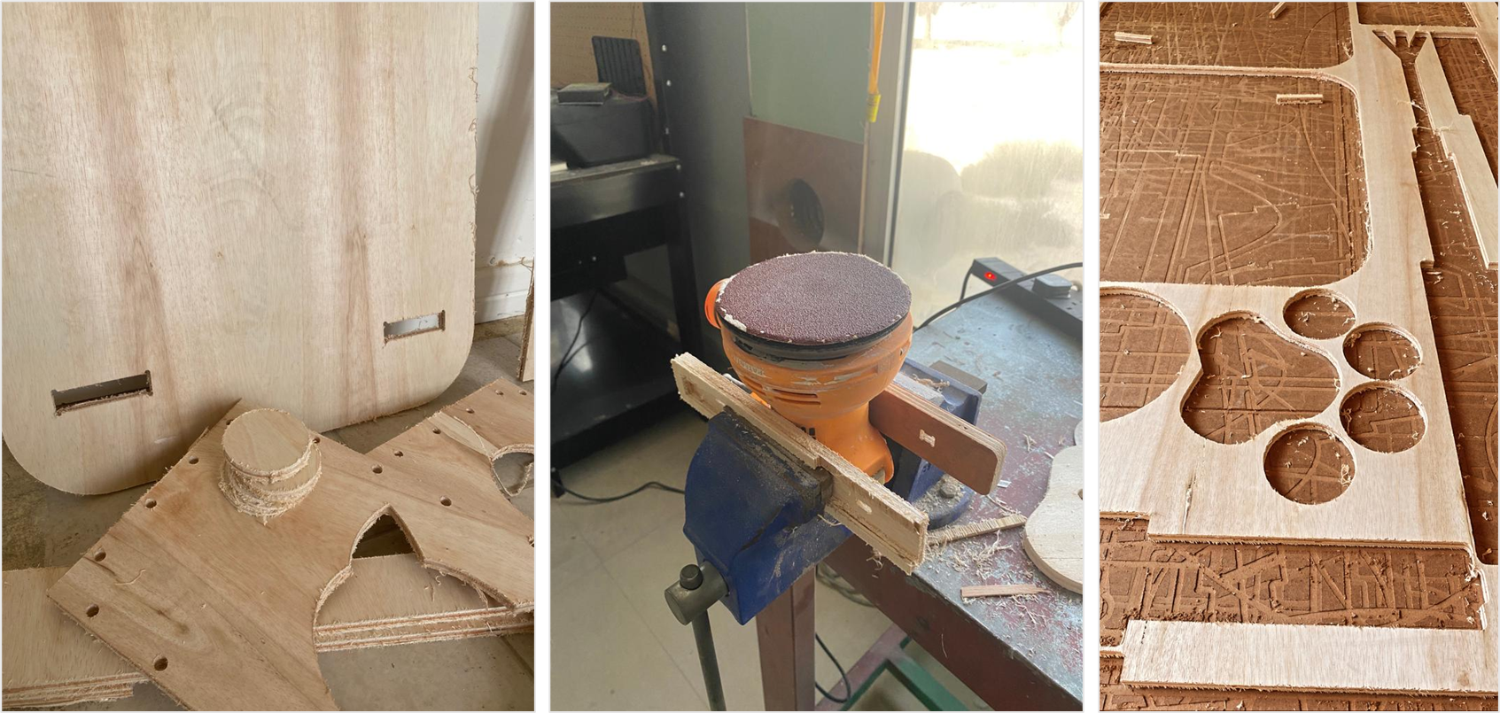
First we started by creating our designs, CNC is a 2d cutting machine so the exported format would be DXF. Personally I like visualizing objects in 3d so I designed my piece as a 3d model and I used Sketchup for that. I don't really recommend using Sketchup, because we faced problems with the DXF file. In our pieces we were asked to use joints to connect the pieces together, the diagram dowwn below helped a lot in the making of the joints and the right size to use.


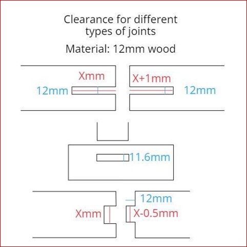
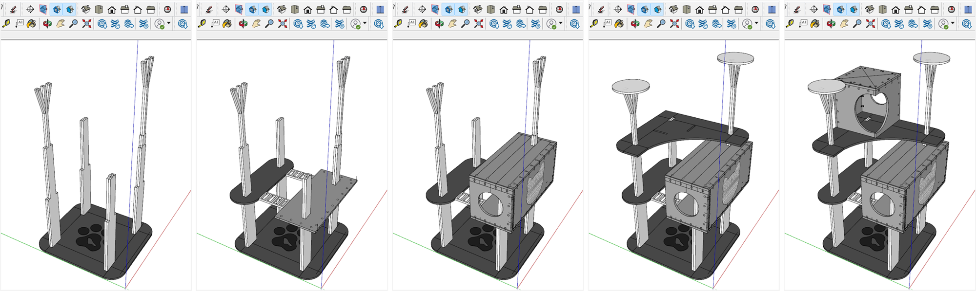
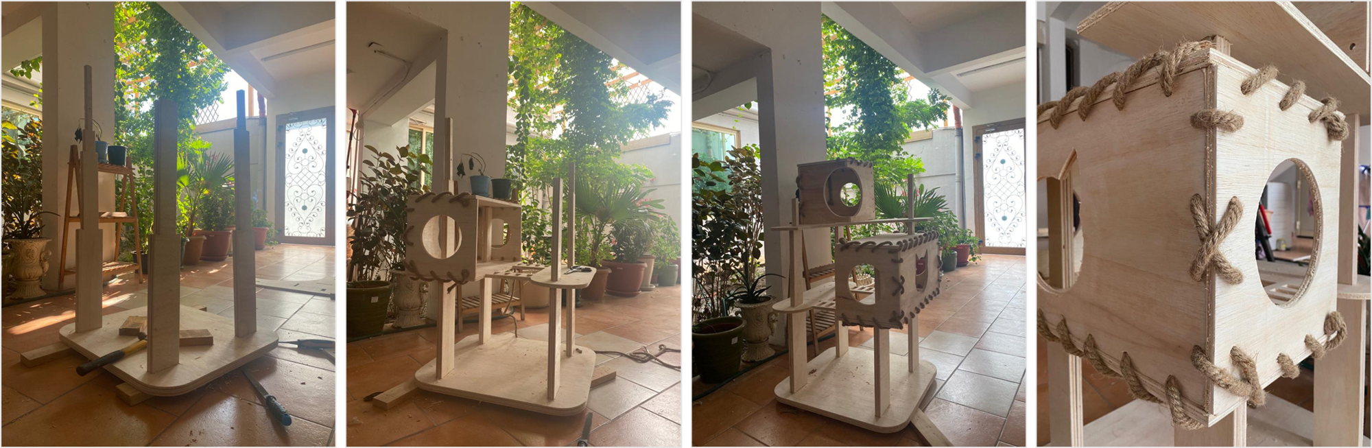
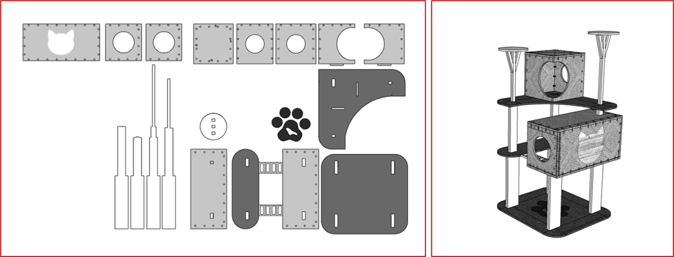
Down below is a picture on the 3d I created in SKETCHUP, the project was a cat tower :) . I used three types of joints, the pocket joint, the normal slide-in joint and lastly the rope joint. I used the rope joints to connect pieces together to make the boxes, scroll down to see how!
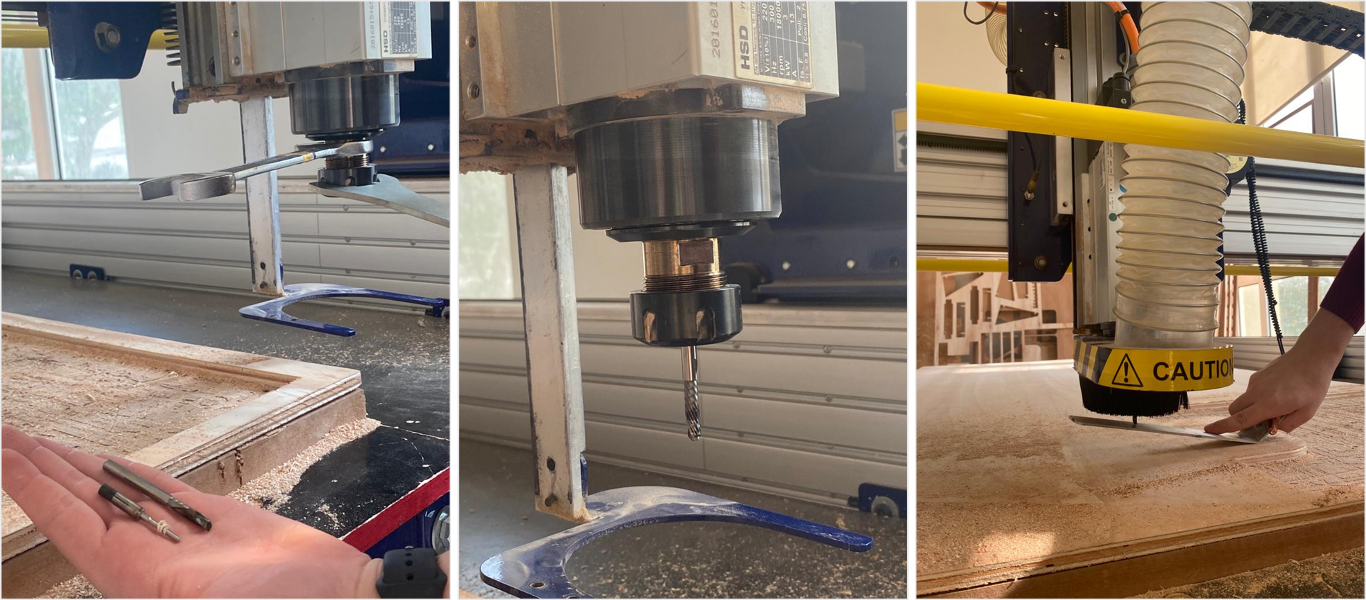
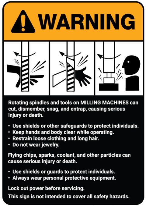


Safety


Down below is a table comparing the different types filaments used in the 3d printers, each filament has its own properties and according to them, we can load the right filament for each product.


Scroll down to see more.


Group assignment:


In the group assignemnt we tested alignment, speeds, feeds, and toolpaths for the CNC machine. You can find it in Sara's page click here .

CNC PROJECT


Individual assignment:

Before starting on the cutting process, here are some tips on how I made the design. I created the design in sketchup, it has similar tools to fusion with different names. I started by creating a sketch using the rectangle tool then I extruded the shape, next I added columns using the same tools. For the boxes I created each surface by its own and I added the holes using the circle and push-pull tool (extrude), then I repeated the process as shown below.

The pictures down below illustrates the pieces and how the are going to be assembled later on.

These are a close-up of how I created the joints using the measurments mentioned above for each joint. The first picture shows how the weight will be distributed amongst the columns, the shelves are going to rest on the columns from the top, this method is repeated in the upper shelves too.


1- Downloading VCARVE,The first step is to download VCARVE, it is the software that can send the machine the 2d drawings to cut them. click here to download it or you can use the one in the computer that is already conected to the CNC machine .

The aim of downloading the software is to prepare all your drawings so you can send it ready to cut. After downloading VCARVE, import all your drawings and start placing them in the sheet as shown below.

2-Connecting lines, make sure that all lines are connected, if they aren't, use select each object by itself and then use the join open vectors tool to close the gaps and create a full shape.

3-Selecting tool path, Next is to select the cut parts, I selected all the parts the needed to be cut from inside and chose the inside button on the window on the right, and repeated the process with the parts that needed to be cut from outside.

Next is to select the bit as shown below, and make sure to increase the depth by 1.2 mm to ensure that the bit will go through the entire depth of the sheet.

The next step, you will notice a warning appearing, it is to let you know that by increasing the depth the bit might cut the bed of the machine, we solve that by adding a sacrafice sheet under the sheet we want to cut, to prevent the bit from cutting the bed of the machine.


4-The cutting process, first you have to make sure that the sheet is placed on the sacrafice sheet, then screw it in place as shown below, to prevent it from moving while the machine is cutting.

Next step is changing the bit according to yur design, and callibrating the Z-axis (photo on the left). The z callibration is how the machine can dedict how low it can go to touch the sheet.

These are the pieces after they were cut, net step is to sand them and I used the sanding machine in the workshop to do so.

Next step is to put everything together, and this is the final result!


click here to downland the dxf file.


click here to downland the sketchsup file.