week3
computer Controlled
Cutting
What I did
-
This week
we were introduced to laser cutting machine, and it's safety measures.
We did a group assignment to characterize the lasercutter’s focus, power, speed, rate,k erf, and joint clearance.
I worked on my Individual assignment.
I created a paarametric design using Fusion.

✎ Laser cutting machine
For precise cutting and designing tasks, a variety of sectors employ laser cutting machines. A powerful laser beam is emitted by the laser cutting device to either precisely cut or engrave a pattern on materials.
✎ Specifications of the Laser cutting machine existing in the lab
Type: CO2
Bed size: 600mm x 900mm
Power: 100watt
Beam width: 0.32mm to 0.10mm depends on material
File formats: 2D formats (.dxf .pdf .ai .svg ...)
✎ Materials that are safe
The laser can cut and engrave. The laser can cut materials such as wood, paper, cork, and some types of plastics. Wood, cardboard, aluminum, stainless steel, plastic, marble, stone, tile, and glass can all be engraved.
✎ Max thickness
Acrylic (max thickness: 12.70 mm)
MDF (max thickness: 6.35mm)
Plywood (max thickness: 6.35mm)
Thin Polycarbonate Sheeting (< 1mm )
Leather (max thickness: 3.18mm)
✎ Prohibited materials:
There are some dangerous materials that shouldn’t be used for laser cutting
1. PVC (Poly Vinyl Chloride)/vinyl/pleather/artificial leather)
Cause: it ruins the optics, causes the metal of the machine to corrode, and ruins the motion control system, and it emits pure chlorine gas when cut.
2. ABS
In a laser cutter, it does not cut properly. It tends to melt rather than vaporize, and it is more likely to catch fire and leave melted sticky deposits on the vector cutting grid. It is also difficult to engrave.
✎ Safety of using laser machine
Close the protection door Keep distance between you and the machine
✎ In case of Fire:
- Use the fire blanket. (Fire blankets are used to smother the flames, restrict them of oxygen, and eliminate the fire before it spreads). - Switch off the machine + the power extension cable.
✎ Emergency Aids and measures:
There are two types of fire extinguisher in the lab, the water based and CO2. for the laser cutting machine the CO2 extinguisher should be used.
Preparation of the file
1. Save your drawing as (.DXF).
2. Thunder Laser RD works should be downloaded.
3. When you launch the software, go to File >> Import.
4. Check that the measurements are accurate.
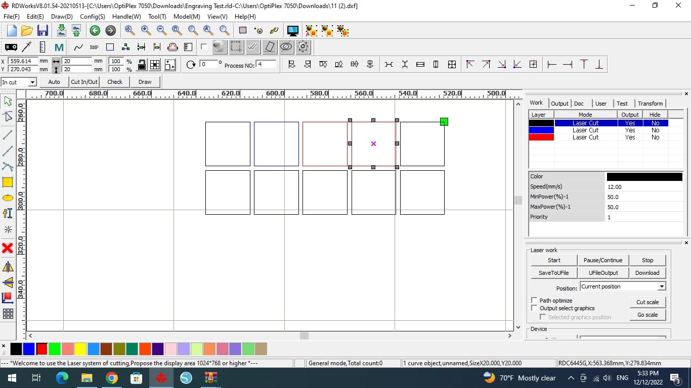
5. If it was rotated, you can change its orientation by double clicking in the middle (X).
6. To cut or engrave any material, two major parameters must be adjusted (power of the laser, speed of laser head movement).
7. Check that your USB cable is properly connected before clicking "Download" to submit the file to the laser cutter, give it a name to recognize it).
Operation

1. Check that all three plugs are connected before proceeding (laser tube cooler , air pump ,vacuum pump).
2. Turn on the power at the mains plug.
3. Turn on the laser by moving the button to the right (means on).
4. Select File, then Enter.
5. To lower or raise the laser bed, use the arrows next to the letter z.
6. Place your sheet.
7. You can either move your sheet to the laser pointer or move the laser itself using the arrows. Set the starting position by clicking the origin button.
8. Close the laser door.
9. Press the green start button.
10. When the cutting is finished and all of the smoke has been vacuumed out, open the laser door.
Group assignment 1
📝Laser focus exercise
The goal of this exercise is to set the focus point that will allow the laser to precisely and accurately cut the material for it to be removed easily from the sheet with a minimum amount of wasted material. to do so we followed these steps:

(STEP01) We used a 20x4 acrylic piece to make a ramp, positioning it on a slope with the nosel just barely contacting the surface.
(STEP02) We cut a straight line that we drew in RDWorks down the acrylic piece using a low power.
(STEP03) We calculated the expected focal point measured from the seem above air intake to material surface.
Findings
When the created line is examined, it displays changes along the acrylic piece. On closer inspection, we can observe that the line begins narrow then gradually expands and becomes imperfect, before returning to its narrowest position towards the end.

From this finding, we can say that the most accurate cuts are those that are generated when the laser is far enough distant from the material to produce concentrated cuts. These cuts are the smallest and thinnest that can be made. In comparison, the thickest, broadest cuts are the most inaccurate and may be characterized as the distance where the laser is out of focus and unable to effectively cut the material as it is either too closer or far away from it.
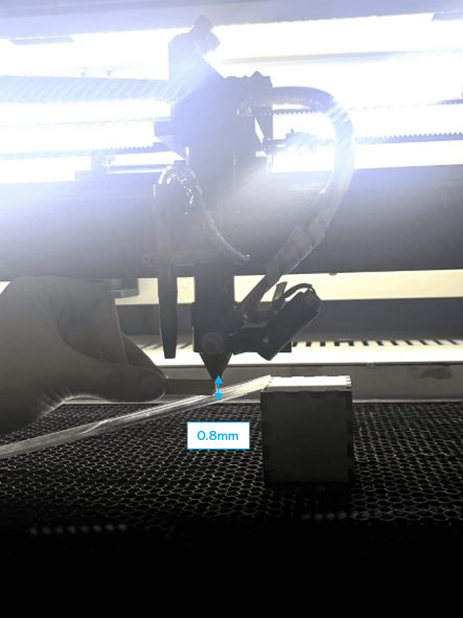
We repeated the cut twice and discovered that the predicted focus point was close to 8 mm. using a 8 mm grey lego block as a guiding tool we adjusted the focus point during the next laser-cutting machine setup for assignment 2 which will be explained next.
Group assignment 2
📝Characterizing Focus, Power, Speed, Rate, Kerf and Joint Clearance
Our goal in doing this experiment was to identify the best speed and power settings for laser-cutting designs.
Speed: The laser nozzle's speed, which is expressed in mm/s, determines how rapidly or slowly it will travel in the directions of X and Y. Higher speed allows the laser to cut the pattern more quickly while decreasing the risk of starting a fire—important for material like cardboard. A substance like acrylic, on the other hand, is more difficult to cut through and needs a slower speed, specially when it is thicker.
Power: The power of a laser when it fires is expressed in Watts. Higher power is needed to cut through harder-to-cut materials like acrylic as well as thicker materials since it will allow for easier cutting. If we simply laser-cut at the least power required, the weaker laser beam caused by lower power won't be a problem because greater powers can also start fires.
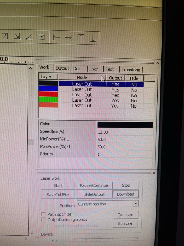
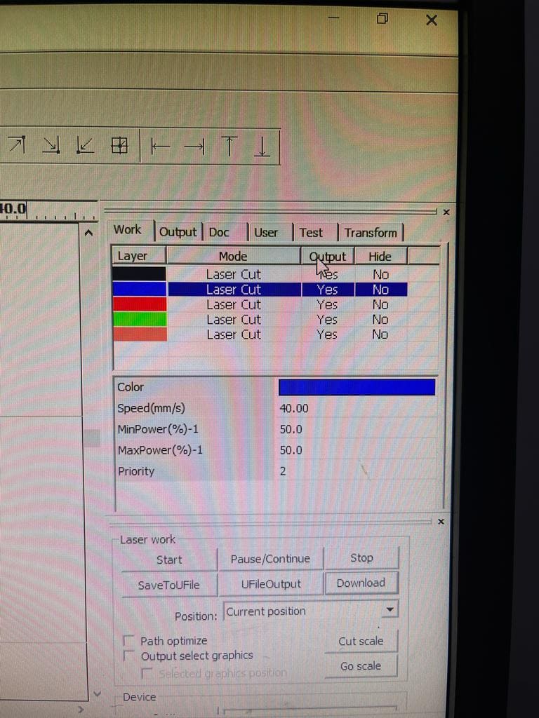
(STEP01) We designed a grid of 4x4 squares in RDWorks. Then, in order to allow for unique power and speed setting selection for our experiment, we color-coded each box. (Black, blue, red, green and pink). For the first 2 squares, we started at a speed of 12 and 40 while keeping the 50 Watts of electricity the same.
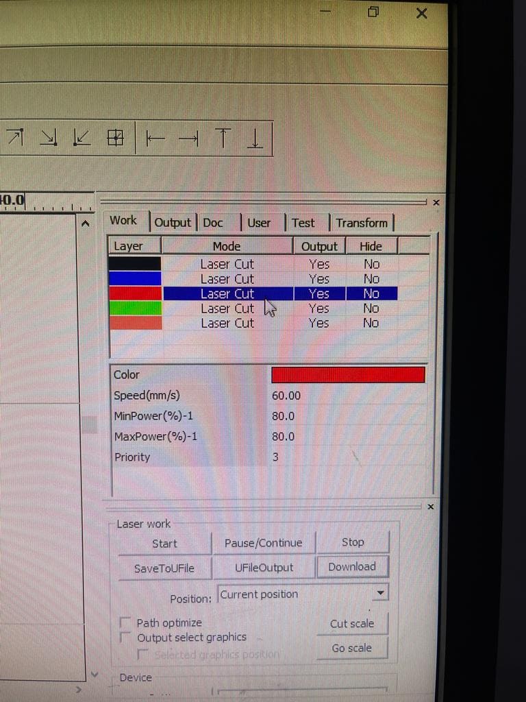
(STEP02) The next square we increased both the speed and power to be 60 (mm/s) and 80 watt.
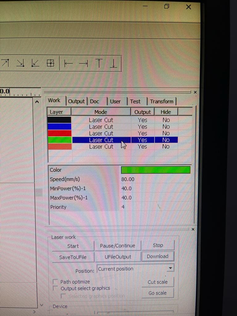
(STEP03) The next square we increased the speed to be 80 (mm/s) and lowered the power to 40W. last square was 90 (mm/s) speed and 70W power were both are higher.

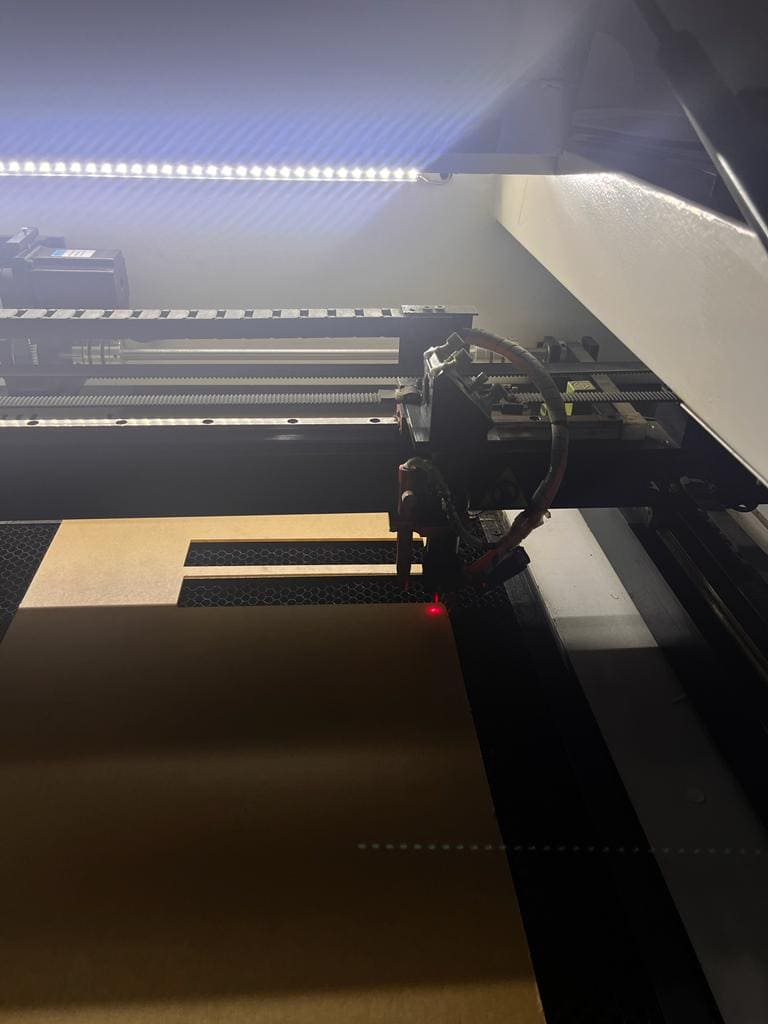
(STEP04) After uploading our square grid files to the laser cutter, we laid down a piece of cardboard and started the laser process. To achieve this, we first used the arrow buttons to move the laser to the location where we wanted it to begin cutting along the bed's axis.
(STEP05) Using the knowledge we gained from the focus point experiment, we corrected the Z axis position once it was in the proper positions on the X and Y axes of the bed. To calculate how far to lower or elevate the laser using the controls, as indicated in the illustration in the previous steps, we used the 8 mm LEGO brick as a guide.
(STEP06) We clicked Origin to indicate the starting point of the cutting. then frame to showcase the outline of the design and where the nozzel will travel. Additionally, by clicking on File and finding our design file We pushed the Start button when we were prepared to begin, and the machine started the cutting process.
Findings
The laser power is an important parameter that determines the ability of a laser to produce quality cuts in the workpiece. performing a deeper cut requires more energy than a shallow cut, thus requiring more laser power. The more you increase the power the more the laser can make clean cuts in materials. in our case, starting off with 50W and increasing it helped us getting clear cuts espesically that the thicknesss of the material was 6mm and it is a cardboard. When we lowered the power to 40 it required us very minimum pressure to push the piece out.
The cutting speed is the speed at which the laser moves over the workpiece.The slower the cutting speed of the laser, the higher the energy supplied, and the higher will be the temperature at the cutting area.
Therefore, when using a laser cutter, the power of the laser determines the optimal dwell time to get the desired output. When you lower the energy you will need a higher speed, thus while when you increase the energy you will need less speed.
However, using high laser cutting power with an extremely slow cutting speed can result in over-burning of the workpiece. Which is the exact same thing that happened for the first square with a speed of 12 and power of 50W. The next square didn’t overburn because the speed wasn’t that low and it was 40. while we kept the same power of 50W.
As a result we can say that maintaining the speed and power can detritmine the clean cuts. a speed of 40 mm/s just like the second square and a power of 60W to 65W gives the clean cut.

Kerf
The kerf is the width of the laser's cut. It results from the removal (Burnt out) of material during the cutting process. we did an experement to showcase the additional size we need to consider while designing before cutting any material.
In RDWorks We created a 2D rectangle that encloses smaller boxes that are all close to one another, represented as a number of parallel lines. We downloaded it, and then we began cutting with a speed of 12 and power 50.


As a result we measured the width of each square and the inner edges of the enclosing rectangle to analyze the kerf that resulted from the cuts. We then compared these measurements to the original dimensions we set the design to determine how much allowance should be made to guarantee that laser-cut pieces will be the same as we planned for.
We first measured the rectangle length and width. the original length was 10cm and after cutting it became 10.04 the original inner width was 2cm and after cutting it became 2.04
Measuring the little rectangles' thickness where it was originally 1 cm each, it became 0.96cm.
Following the cutting, the outcome was as follows: Each square may be seen to not entirely fit into the inner rectangular area. This is because each square had a different kerf and more material was wasted cutting around it. We can conclude that average kerf for the majority of the parallel tiny rectangular pieces was about 0.2 mm. Because of this, we may probably raise the dimension in our designs by that amount to ensure that the final dimension after cutting are same as the original dimension. another thing to put in mind is that using a high-powered laser can result in overheating of material, thereby melting the workpiece and increasing the width of the cut, therefore the power should be also considered

Individual Assignment
📝Parametric Design
Parametric Design
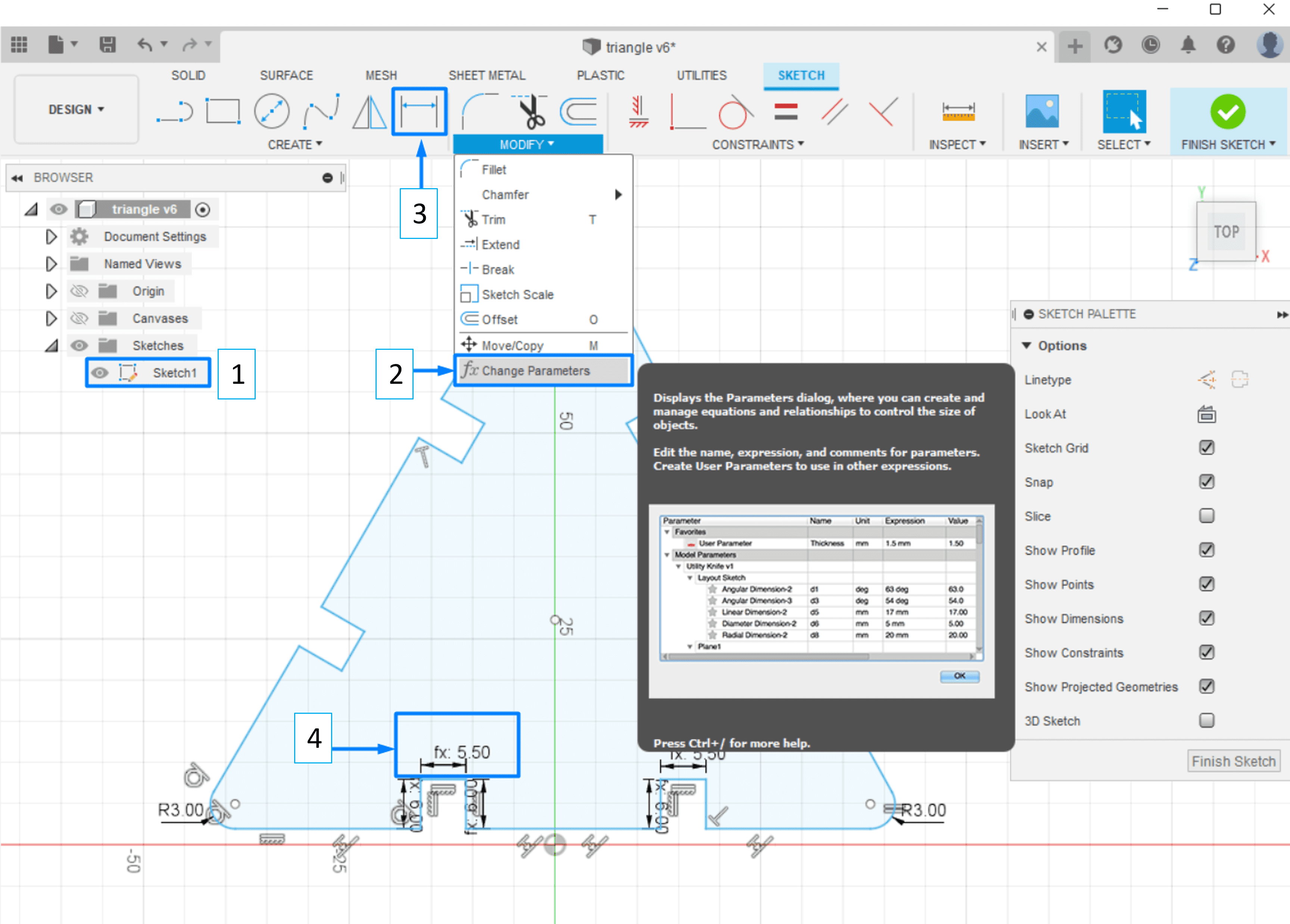
With parametric design, you may quickly modify a model's proportions without having to go back and make corrections at each individual step and each side espicially if you have a complicated design with too many joints. You can add new parameters and specify their values. You can utilize this parameter whenever you're specifying dimensions in a sketch by going to modify then changing parameters. You may instantly resize your model using parameters and see the adjustments take place in real time.
Press-Fit Construction Kit
Means assembeling a model with no glue, screws, or other fasteners. the components must simply fit together. The design should feature joints that precisely fit together. There should be several different methods to assemble the parts and end up with at least 2 diffrent models.
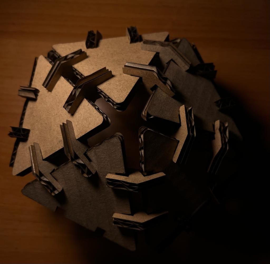
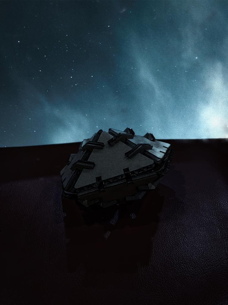
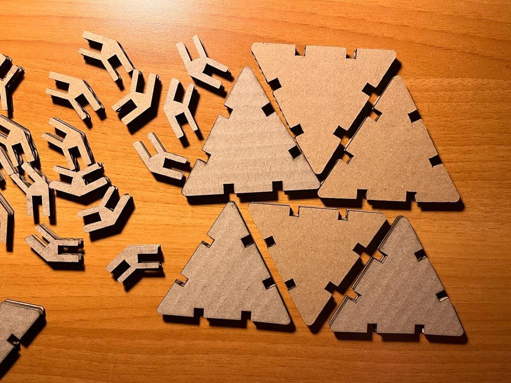
Using Fusion360, I made a design that consists of triangles and hinges that, when put together, may either form a ball or a spaceship.
(STEP01) I began by sketching out the triangle with all the necessary dimensions. I used Modify>> Change Parameters to assign the desired dimensions since if a side or angle is given a dimension, the design would begin to constrain and make it harder for the user to move freely. Additionally, you may click on Drawing Dimension while your cursor is on a line in a sketch and write the word you chose a dimension for to automatically modify the line and its dimention.
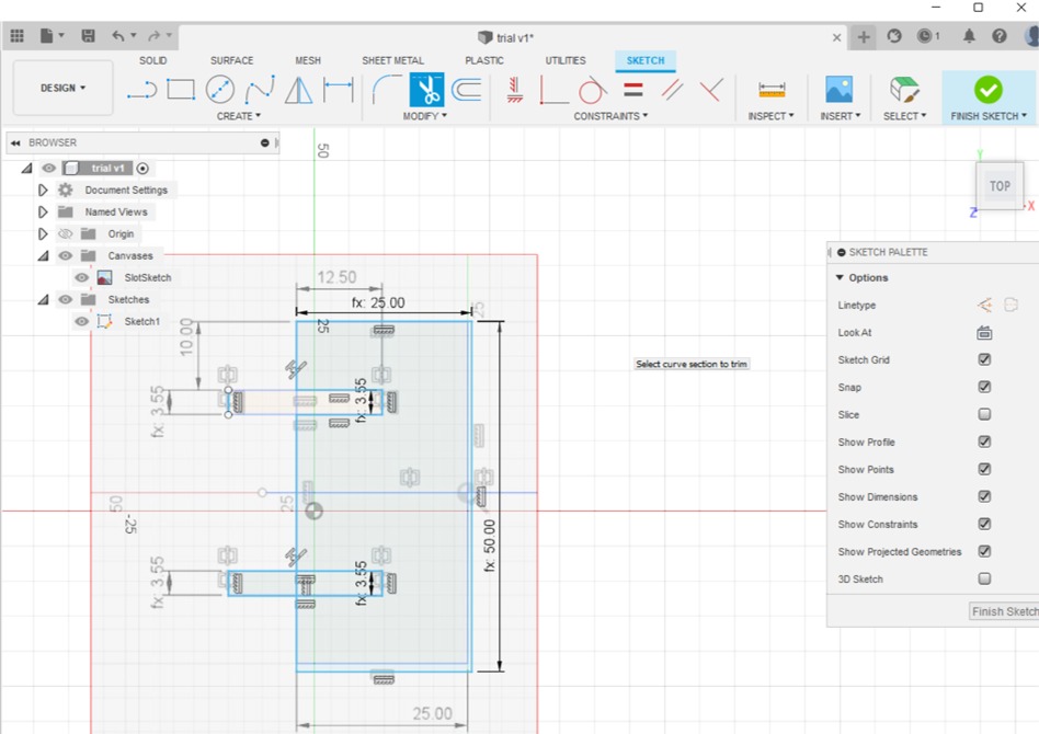
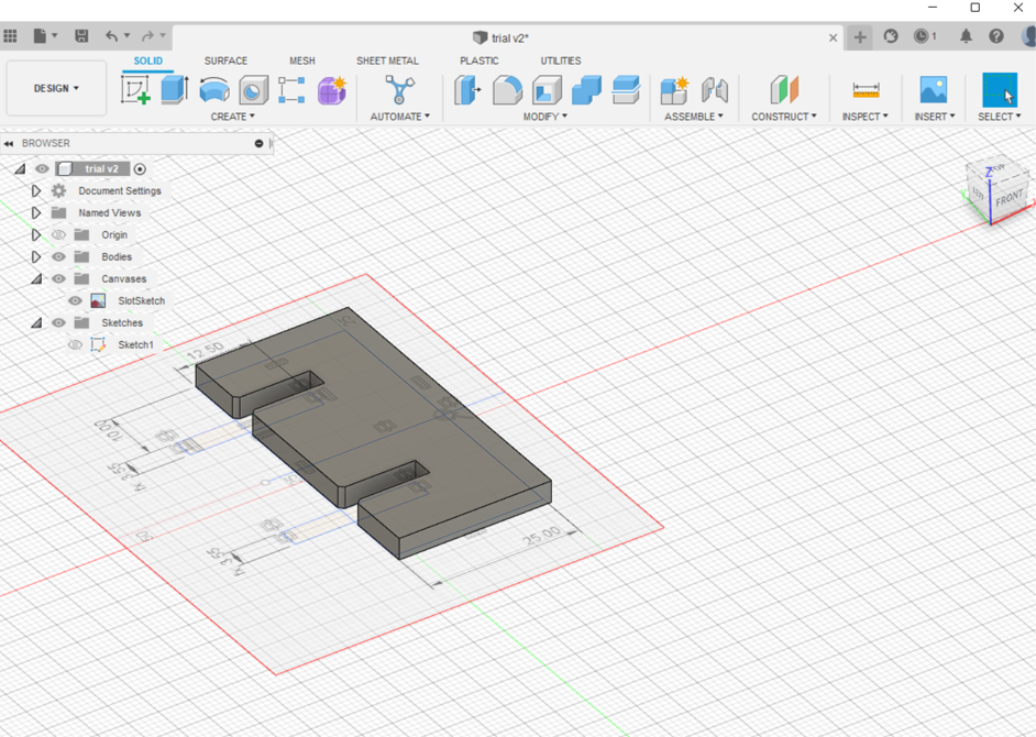
(STEP02) I repeated the steps for the connectors.
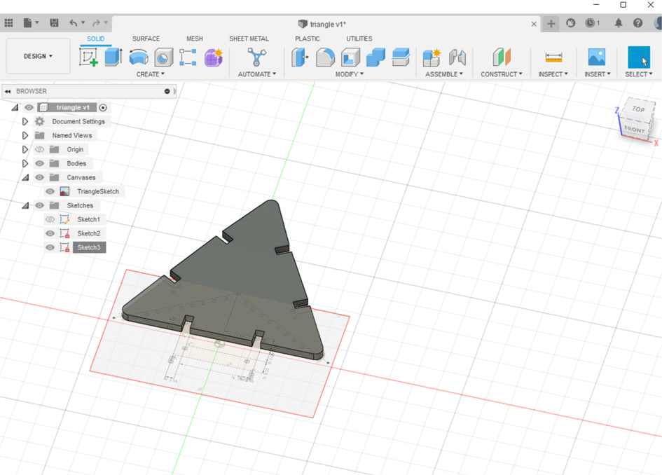
(STEP03) As explained in a previous section on week02, I extruded the shapes and then for getting the DXF file i created a new sketch above the surface of each of the triangle and the hinge (connector).
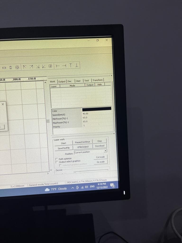
(STEP04) I downloaded my file in order to laser cut it, and assigned te speed 40 and the power 65, and I used 5mm sheet of Cardboard.
Important note: I considered the burnt out material that will occur so I added 0.5mm of dimention to my opening where the hinges will meet.
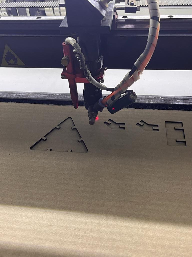
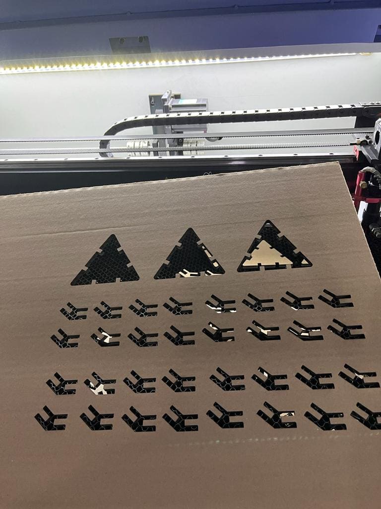
(STEP05) As you can see, the pieces were easily removed from the cardboard.
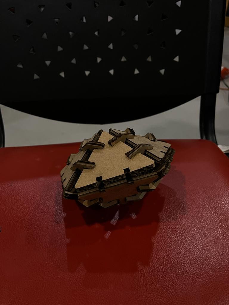
(STEP06) I slightly squeezed the triangular cardboard to make the hinge fit perfectly before starting to put the pieces together. To make the spaceship more aesthetically pleasing and recognizable I put it together and edited the colors and background it in Photoshop.
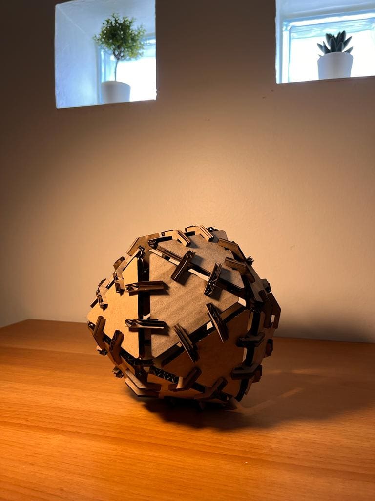
(STEP07) To assemble the ball, I had to cut out more pieces a total of 18 triangle and 52 hinge.

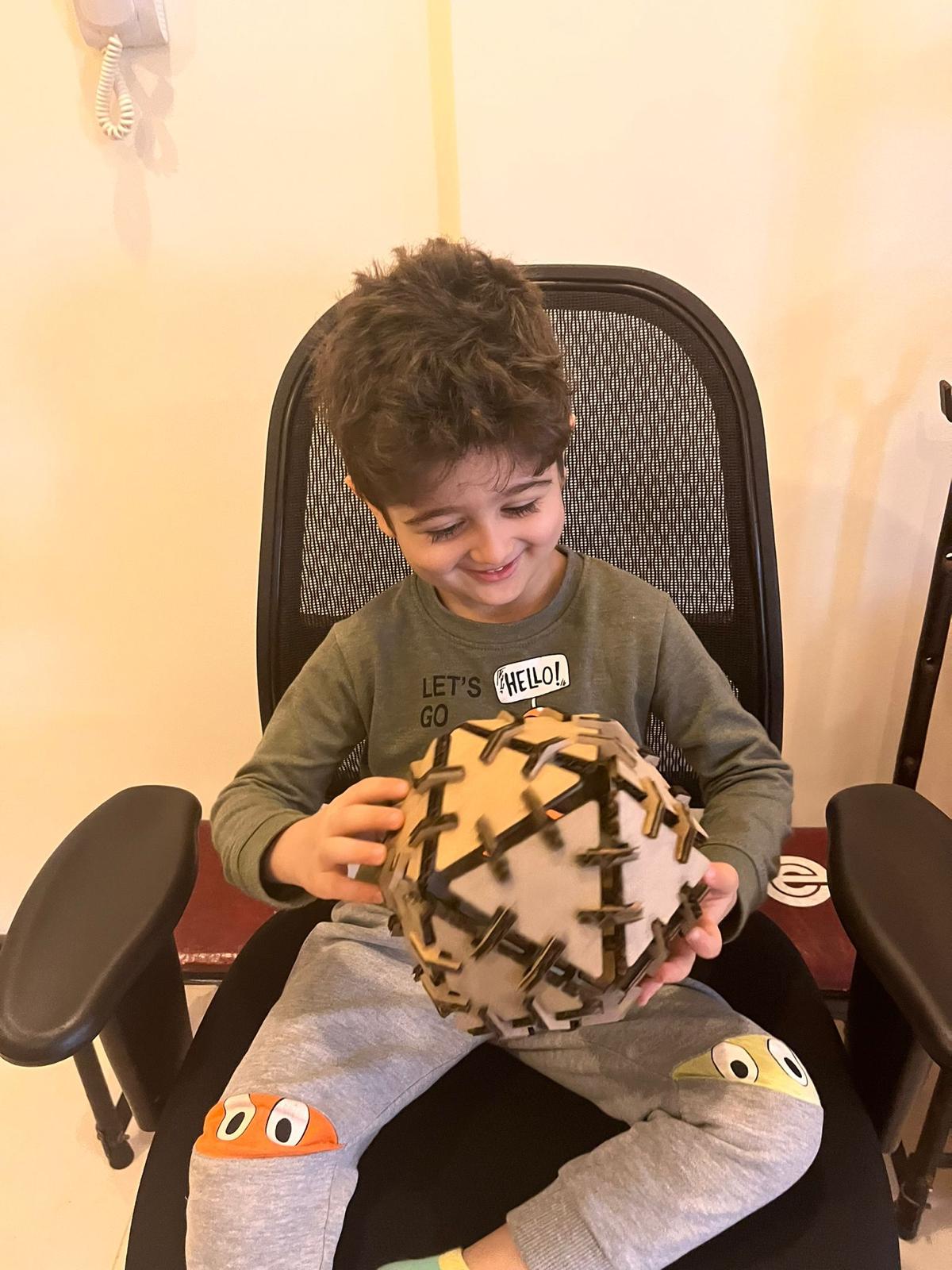
Also a pic of my nephew who likes balls and soccer in general, and you can tell how happy he was :P
Individual Assignment
📝Vinyl Cutting
Cricut Explore Air 2 machine ✂
This machine can cut cardstock, vinyl and iron-on to specialty materials like glitter paper, cork, and bonded fabric.
Group Assignment
📝Iron-on
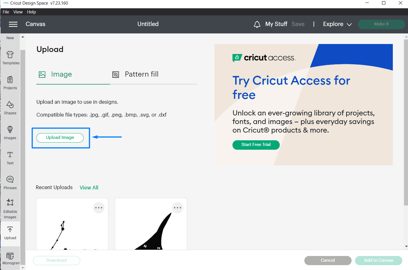
(STEP01) We started by downloading cricut software and we put a text with our names
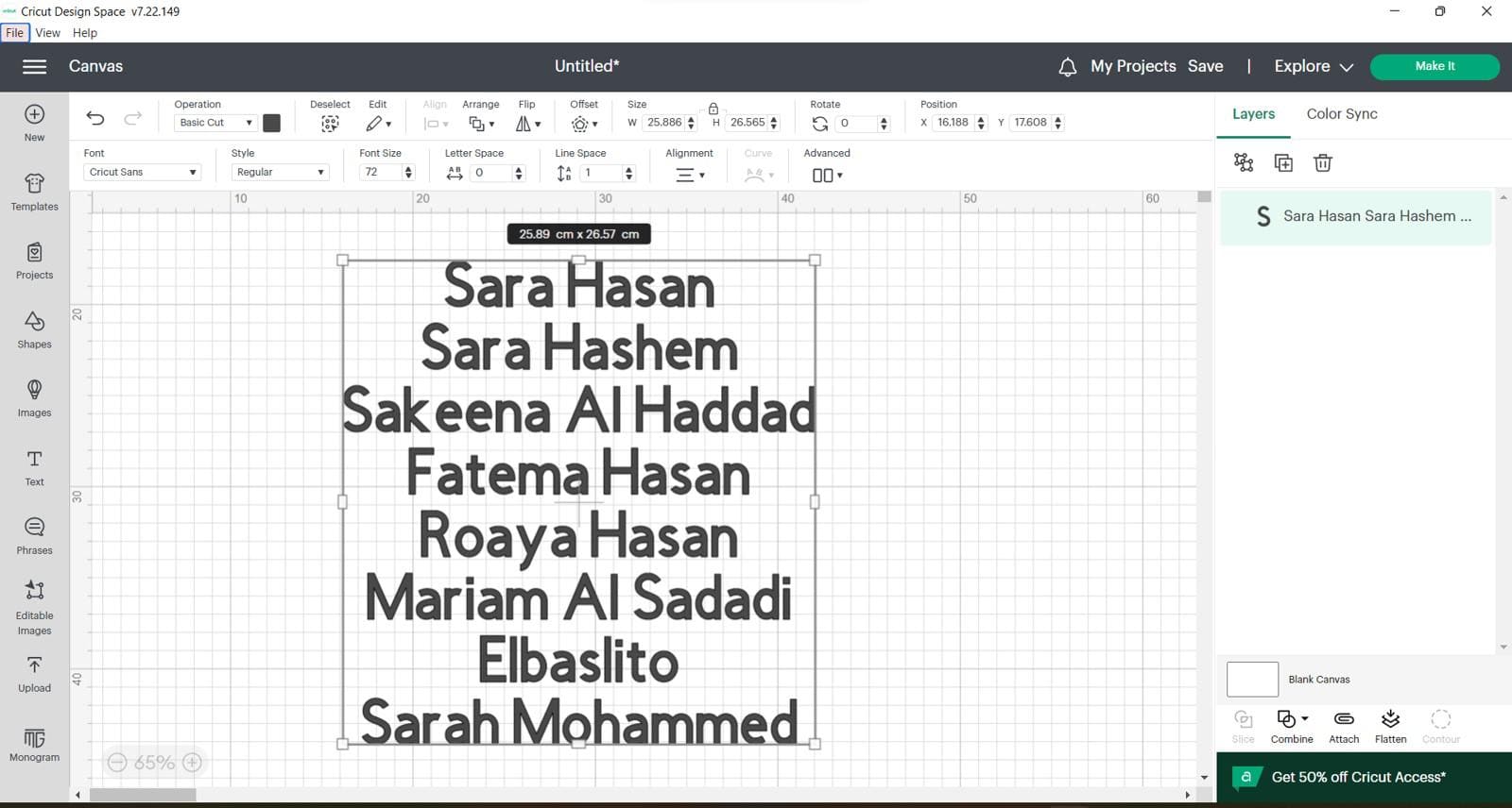
(STEP02) for an Iron-on sticker you should mirror the design in the software itself before getting it cut out.
This is before
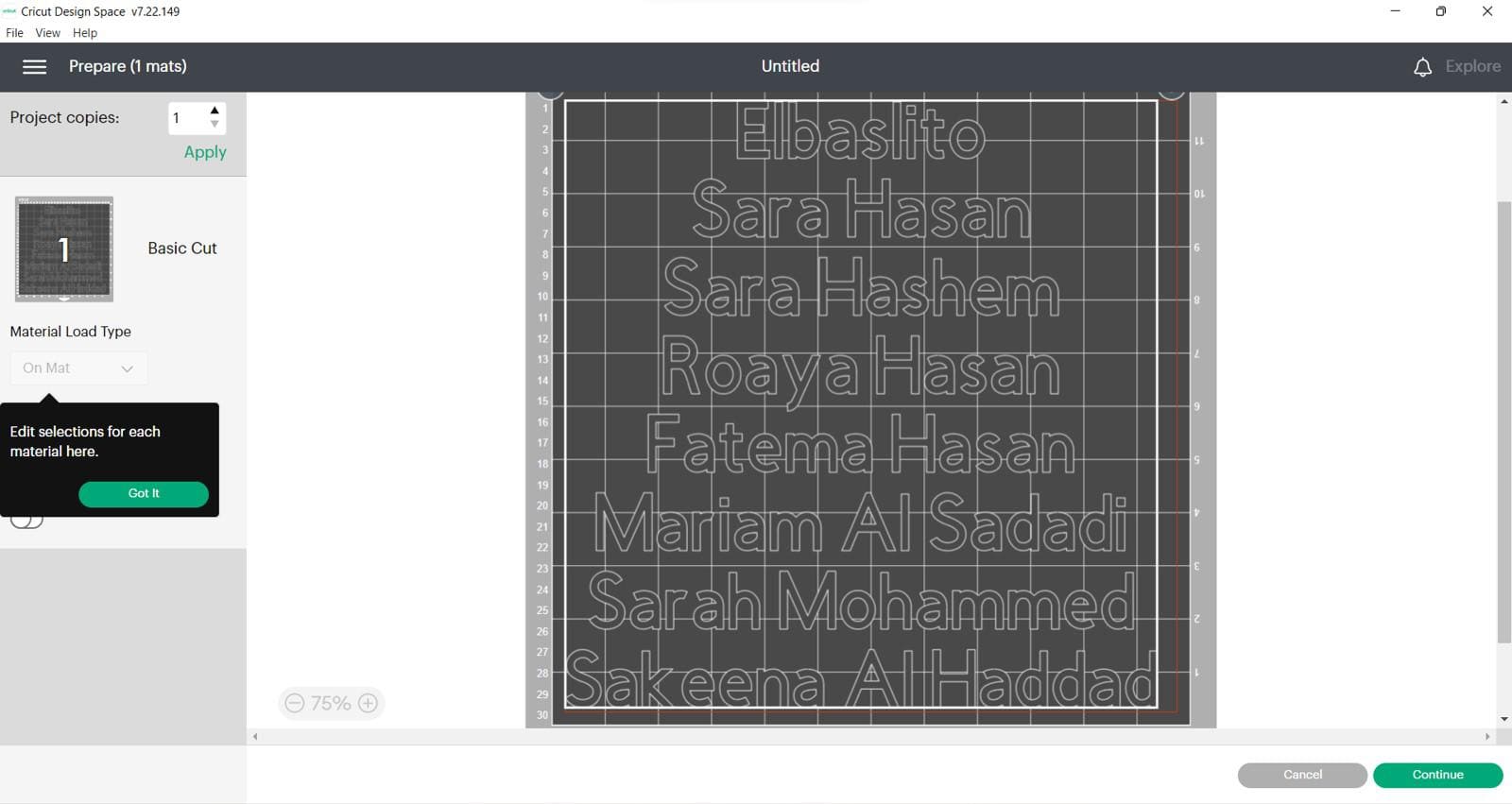
This is after
(STEP03) place yout vinyl on the mat and turn the dial to Iron-on, load the mat and press go

(STEP04) After unloading the mat you need to take out the nagative parts.
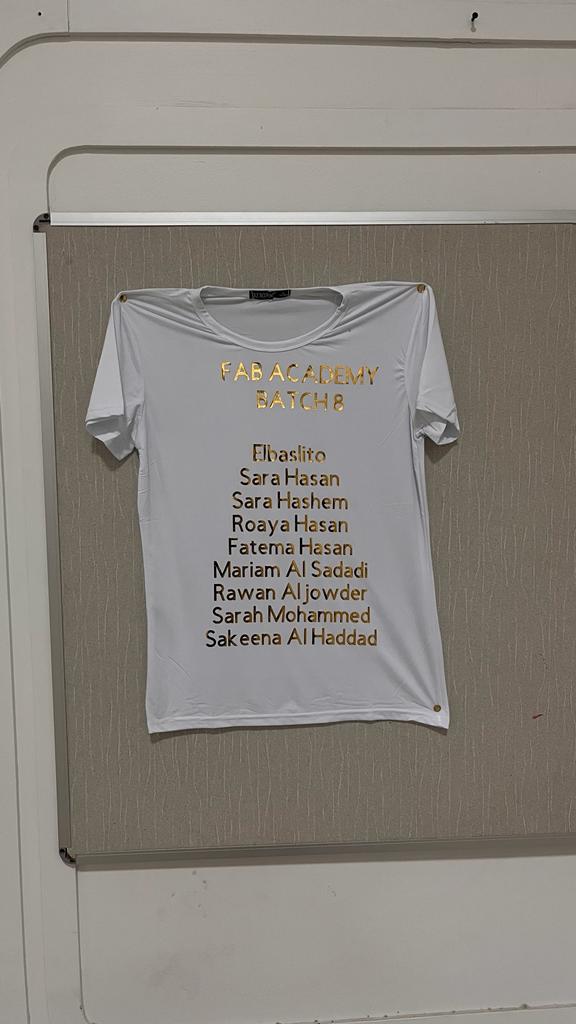
(STEP05) Because we had diffrent letters that are seperated we had to use a transparent transfer tape so we can apply the vinyl to the t-shirt easily.
(STEP06) The last step would be ironing and this is how it turned out
Indivisual Assignment
📝Vinyl
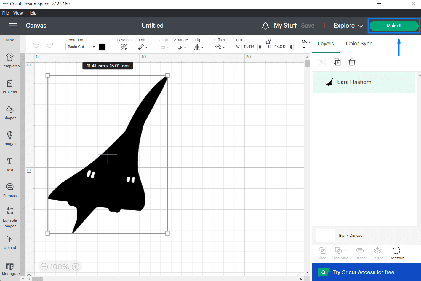
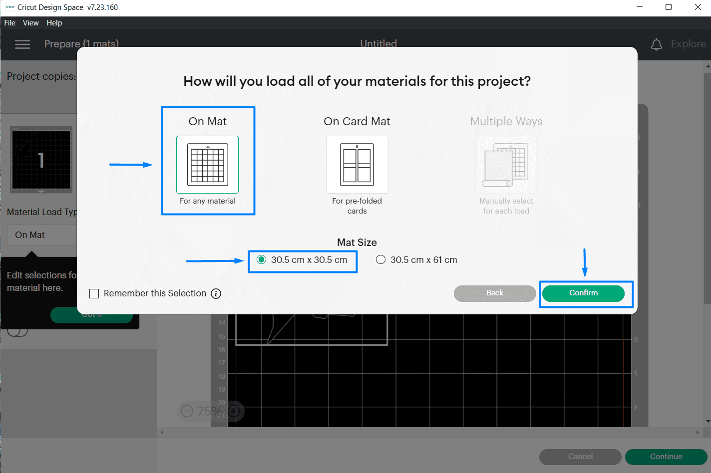
(STEP01) I saved a picture of an aircraft called "Concorde" and uploaded it to Cricut and rescaled it, Then I clicked on make it option.
🖐FACT: Did you know that concorde is the first passenger aircraft to fly more than twice the speed of sound?
(STEP02) A window will apear. I chose mat printing as the medium and the size of the matt then confirm.
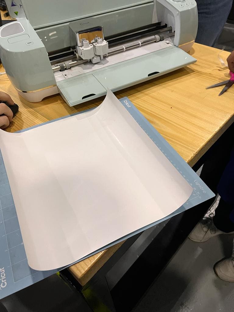
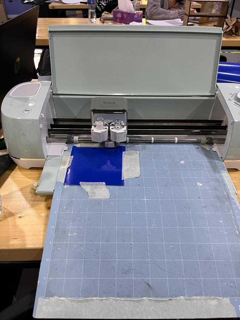
(STEP03) Using a tape I sticked the vinyl into the mat and loaded it to the machine by making sure the machine pulls the matt towards the inside. I turned on the dial to choose Vinyl. this time I didn't need to flip my design because it will be sticked directly.
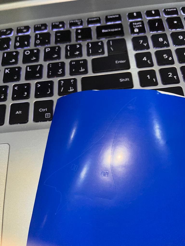
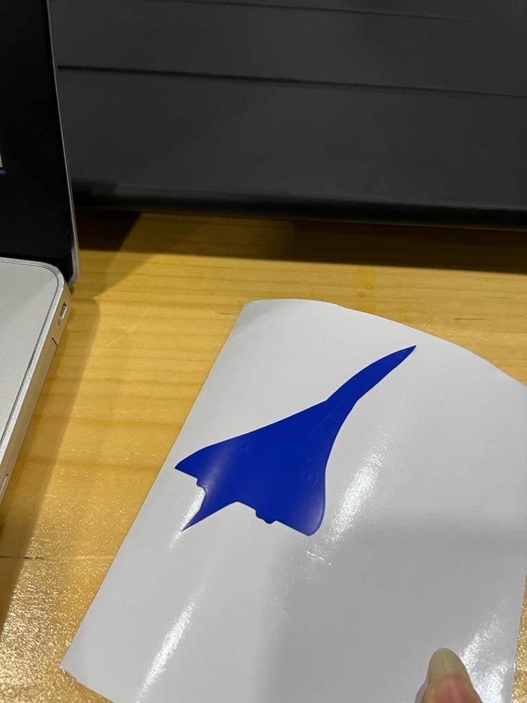
(STEP04) After cutting I removed the matt and started taking out the nagative parts using a tweezers and my design was ready so I used it as a sticker for my laptop.

🔗 Download Files
Hinge-Fusion file
Triangle-Fusion file
Hinge and triangle DXF
🔗 Resources
concorde image
04
Contact Me
Mobile Numberr
+973 35011840
Email
sarahashiim18@gmail.com
Social Network