week6
Embedded
Programming
What I did
-
This week
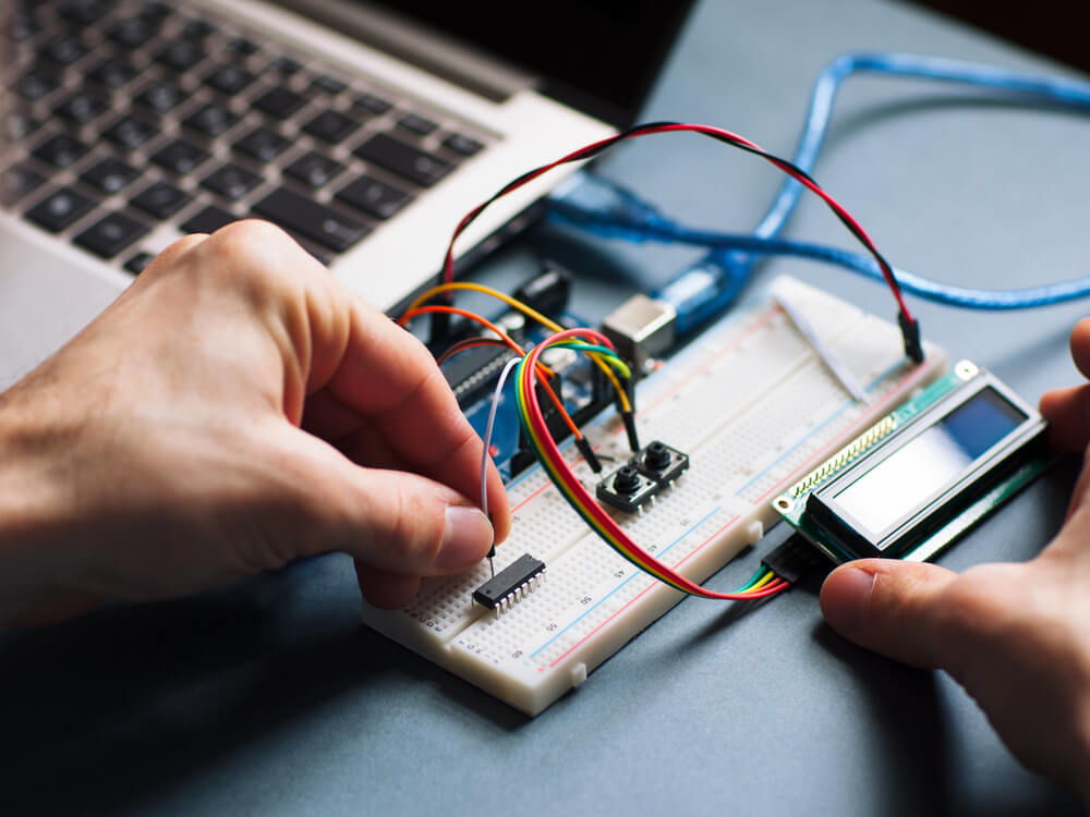
we were introduced to the microcontroller and its power supply.
I did a group assignment comparing between the different types of microcontroller boards
I worked on my indivisual assignment.

Microcontroller
Numerical control, which designates a software program to control an object, is used to operate machines in CNC production. G-code, another name for the programming language used in CNC machining, is used to specify how a particular machine should behave in terms of its speed, feed rate, and synchronization. In essence, CNC machining enables machine tool tasks to be pre-programmed for speed and location, and to be executed by software in predictable, repeating cycles, all with little input from human operators. A 2D or 3D CAD drawing is created for the CNC machining process, which is then converted into computer code for the CNC system to execute. The operator runs the software once it has been inputted to make sure there are no coding errors.
There are three main DC voltage sources available to supply power for our microcontroller projects: Batteries, wall adapters or the USB port of a computer. Generally, the power level requirement is dictated by the requirements of the devices that you use to build the circuit.
When they first became available, microcontrollers solely used assembly language. Today, the C programming language is a popular option. Other common microprocessor languages include Python and JavaScript.
Elements of a microcontroller
It's possible to imagine a device's CPU as its brain. The microcontroller's operation is controlled by the way it processes and responds to different instructions. Simple mathematical, logical, and I/O operations are required for this. Additionally, it conducts data transfer operations, which transmit commands to other embedded system parts.
A memory chip is an electronic component which can store a program, data or both.
Voltage is the pressure from an electrical circuit's power source that pushes charged electrons (current) through a conducting loop, enabling them to do work such as illuminating a light. In brief, voltage = pressure, and it is measured in volts (V).
A microcontroller's memory is used to store the data that the processor receives and uses to respond to instructions that it's been programmed to carry out. A microcontroller has two main memory types.
1.Program memory: Program memory is where the instructions that the CPU executes are permanently stored. Program memory is non-volatile memory, which means it can store data indefinitely without a power supply.
2.Data memory: Data memory is needed to store temporary data while instructions are being carried out. Data memory is volatile, which means the information it stores is only kept current if the device is plugged into a power source.
3.I/O Peripherals: The processor's interface with the outside world are the input and output devices. Information is received through the input ports and sent as binary data to the CPU. After receiving the data, the processor transmits the appropriate instructions to output devices that carry out activities not controlled by the microcontroller.
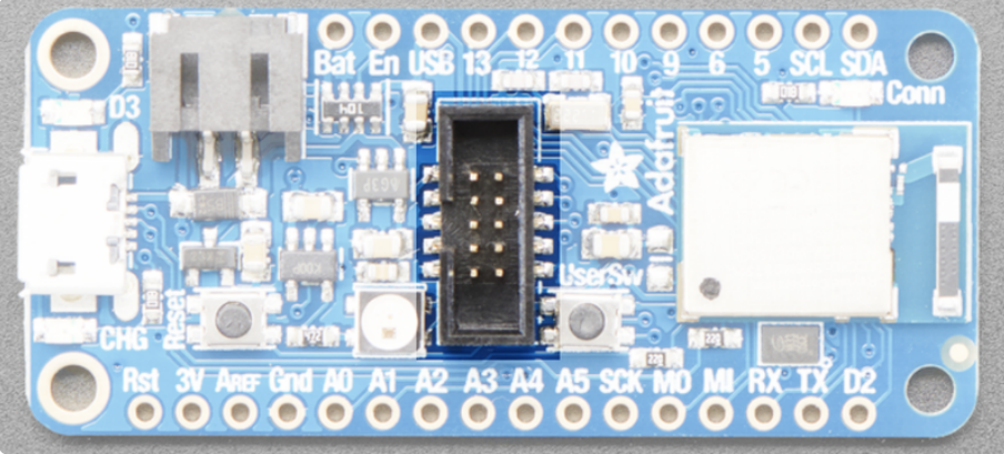
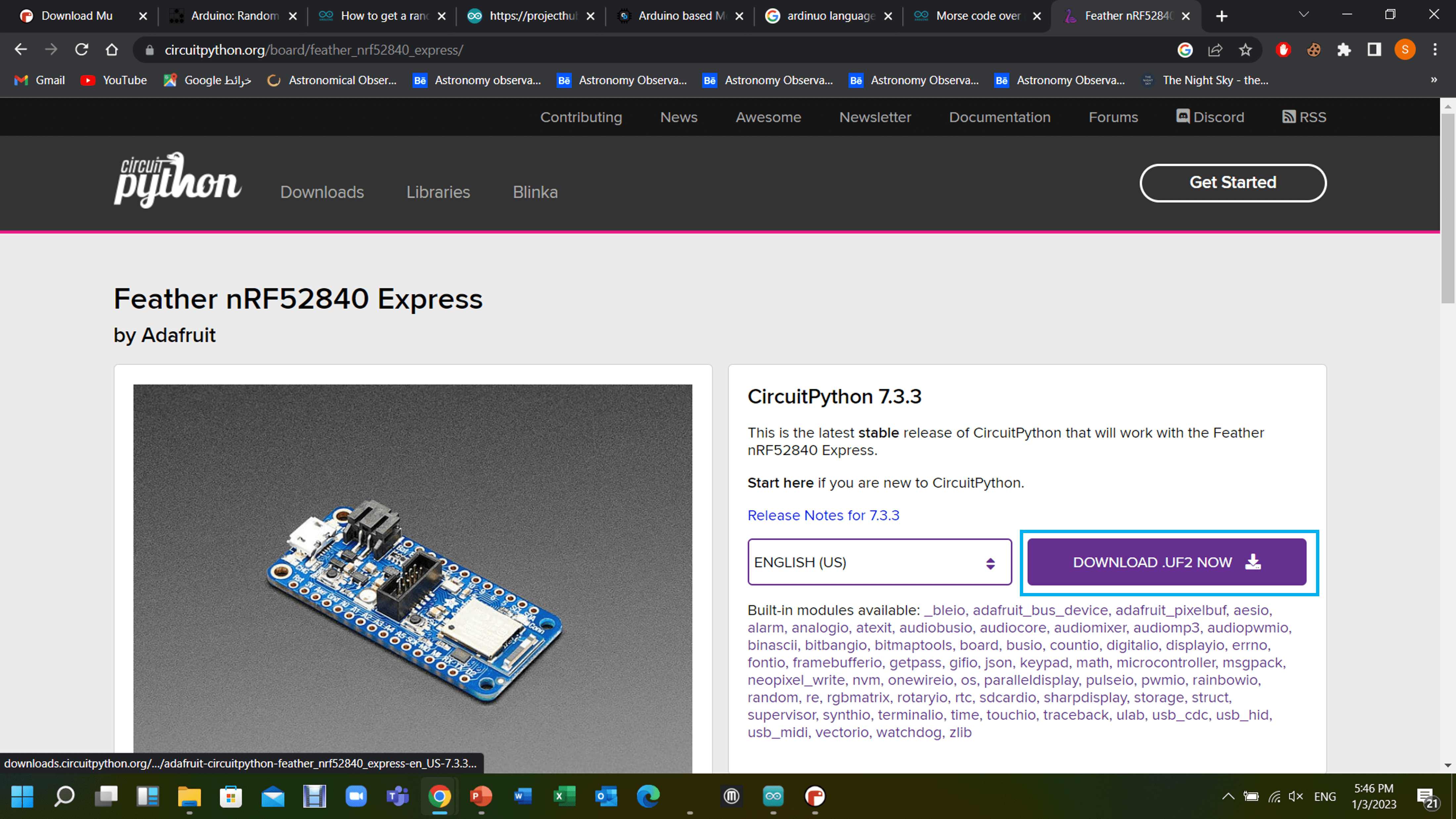
Adafruit Feather
The new member of the Feather family, the Adafruit Feather nRF52840 Express, has Bluetooth Low Energy and native USB connectivity.
1. Power Pins
A typical microcontroller can have between 6 and 60 pins on it, to which you're expected to attach power connections, input and output connections, and communications connections. Every microcontroller has different configurations for its pins, and often one pin will have more than one function.

3V: This pin is connected to the output of the on board 3.3V regulator. It can be used to supply 3.3V power to external sensors, breakouts or Feather Wings.
LIPO Input (Bat): This is the voltage supply off the optional LIPO cell that can be connected via the JST PH connector. It is nominally ~3.5-4.2V.
VREG Enable (En): This pin can be set to GND to disable the 3.3V output from the on board voltage regulator. By default it is set high via a pullup resistor.
USB Power (USB): This is the nominal 4.5-5.2V voltage source that comes from the USB connection.
2. I2C Pins
I2C pins on the nRF52840 require external pullup resistors to function, which are not present on the Adafruit nRF52840 Feather by default. You will need to supply external pullups to use these. All Adafruit I2C breakouts have appropriate pullups on them already.
3. User/DFU Switch
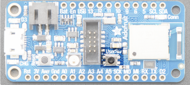
Holding this button down coming out of a board reset will also force the device to enter and remain in USB bootloader mode, which can be useful if you lock your board up with bad application code.
4. SWD Connector
A 2*5 pin 0.05" standard SWD header is populated on the boards. This allows you to use something like a Segger J-Link () and a 1.27mm SWD cable () to connect from your PC to the nRF52840.
5. LEDs
The nRF52840 Feather Express comes with a variety of LEDs that may be utilized as status indicators or put under user control in your application:
Basic LEDs

There are three basic LEDs available on the nRF52840 Feather Express:
D3 is a general-purpose RED LED that can be used for blinky, or other purposes. When running in bootloader mode it is used under the control of the bootloader as a status indicator, with a rapid blinky pattern indicating that the board is currently in DFU bootloader mode. This LED is on D3 (or P1.15). Programmatically you can access this LED as RED_LED.
CONN can be used as a general-purpose BLUE LED, but is generally controlled by the examples to indicate connection status for BLE. This LED is on P1.10. Programmatically you can access this LED as BLUE_LED.
CHG indicates that the on-board LIPO charger is currently charging the connected LIPO battery cell, using USB as a power supply.
6. RGB NeoPixel
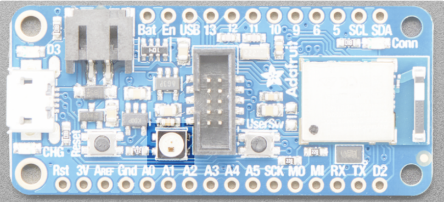
In addition to the basic LEDs, there is also a single RGB NeoPixel (connected to P0.16), which can be programmatically access as PIN_NEOPIXEL.
7. 16MBit (2MB) QSPI Flash

A 2MB Quad-SPI flash is also included on the board by default. QSPI requires 6 pins, which are not broken out on the 0.1" pin headers to avoid conflicts.
Programming Environment
In a general sense, a programming environment combines hardware and software that allows a developer to build applications. Developers typically work in integrated development environments or IDEs. These connect users with all the features necessary to write and test their code correctly. Different IDEs will offer other capabilities and advantages.
The Arduino Integrated Development Environment - or Arduino Software (IDE) - contains a text editor for writing code, a message area, a text console, a toolbar with buttons for common functions and a series of menus. It connects to the Arduino hardware to upload programs and communicate with them.
A block is a program region containing definitions of variables and that delimits the regions where these definitions apply. In C programming language, a block is created using a pair of curly braces. The beginning of the block is denoted by an open curly brace '{' and the end is denoted by a closing curly brace '}'. The block collects statements together into a single compound statements. An example to that is showed below:
<#includeint main() { int n = 1; { int n = 2; printf("%d\n", n); } printf("%d\n", n); }

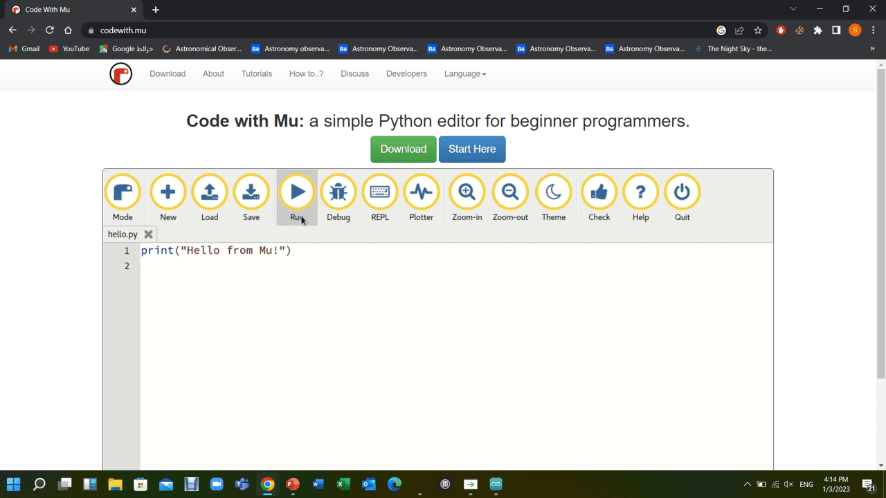
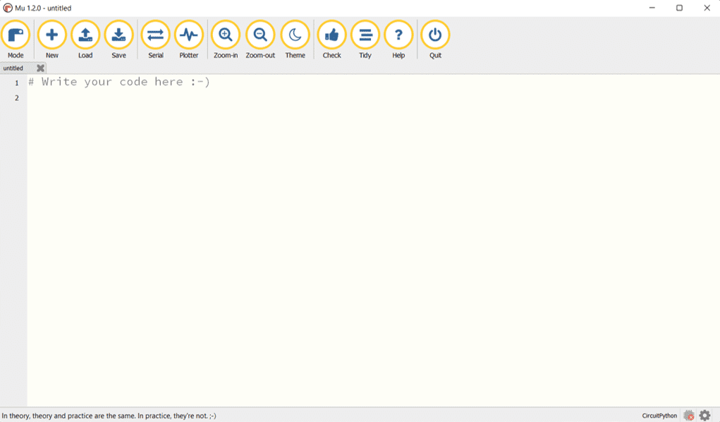
Mu is a Python code editor for beginner programmers. This means Mu makes it very easy to create, run and revise your Python programs as you learn to code in Python. Mu is very simple and easy to understand.
Python is an interpreted, object-oriented, high-level programming language with dynamic semantics. It was originally released in 1991. Python's simple, easy to learn syntax emphasizes readability and reduces the cost of program maintenance. The Python interpreter and the extensive standard library are available in source or binary form without charge for all major platforms.
Group Assignment
For the group assignment which you can find by clicking here. we compared between the different types of microcontroller boards, as well as searching for different programming languages and compare between them.
Individual Assignment
I had to download two different programming environments—the Arduino IDE and Mu Editor—in order to begin programming the microcontroller. The microcontroller is programmed with the desired commands using these two programs.
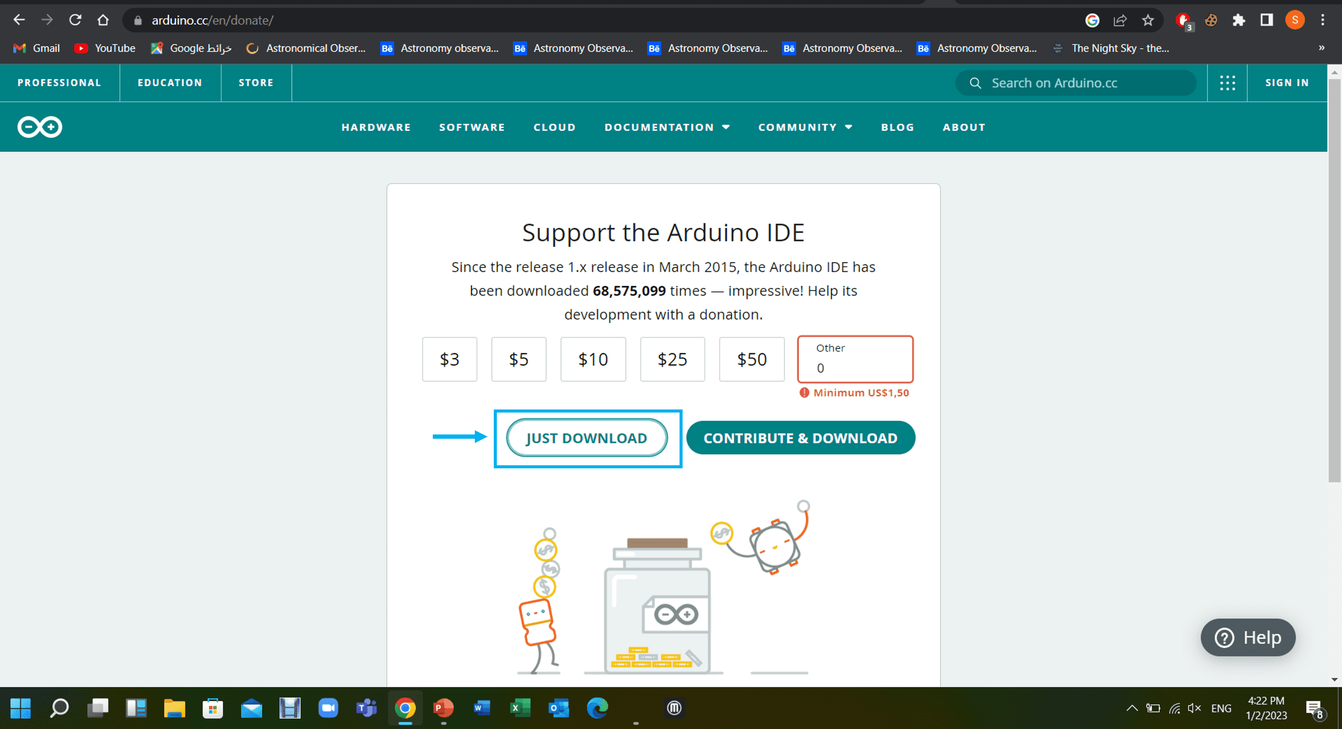
1. Downloading and working in Arduino software
Lunch Arduoino website and click the "just download" button.


Upon installation, the software will be launched.

Click file>> preferences then copy the url link

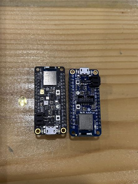
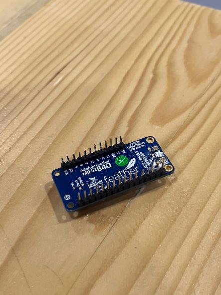
To learn the fundamentals of programming a microcontroller, I used an Adafruit Feather nRF52840 Express as my microcontroller.
Info! There is another type of the same microcontroller called Sense and it comes in Black

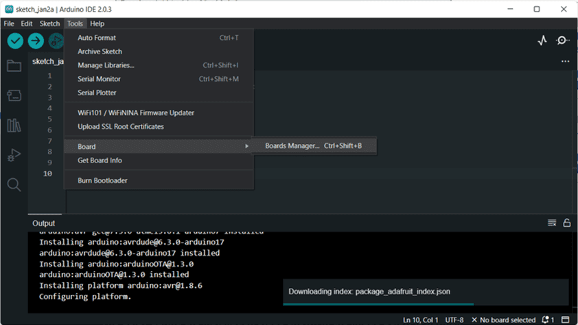
Go to tools >> Board >> Board Manager, and install Arduino AVR Boards
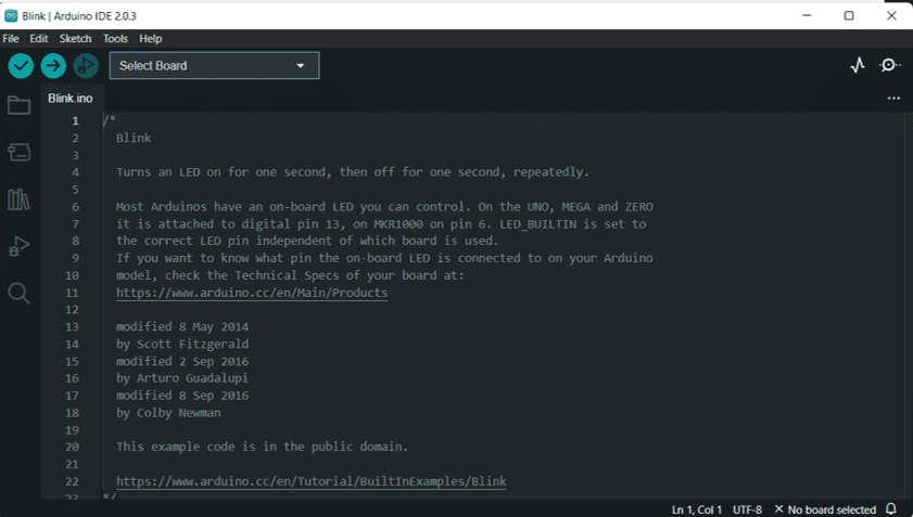
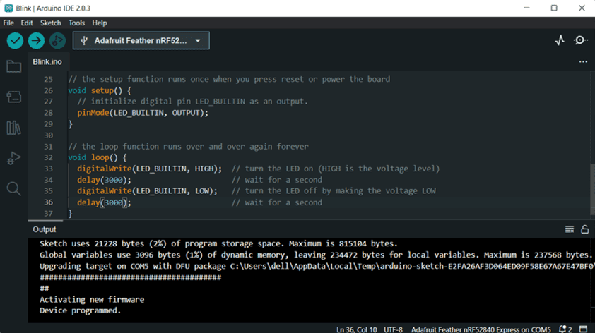
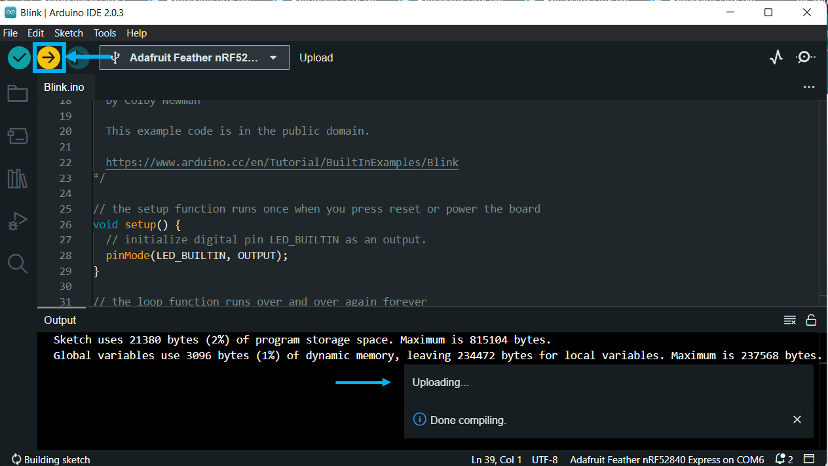
Go to a Basic Blink example to try changing the values and see how the microcontroller will respond

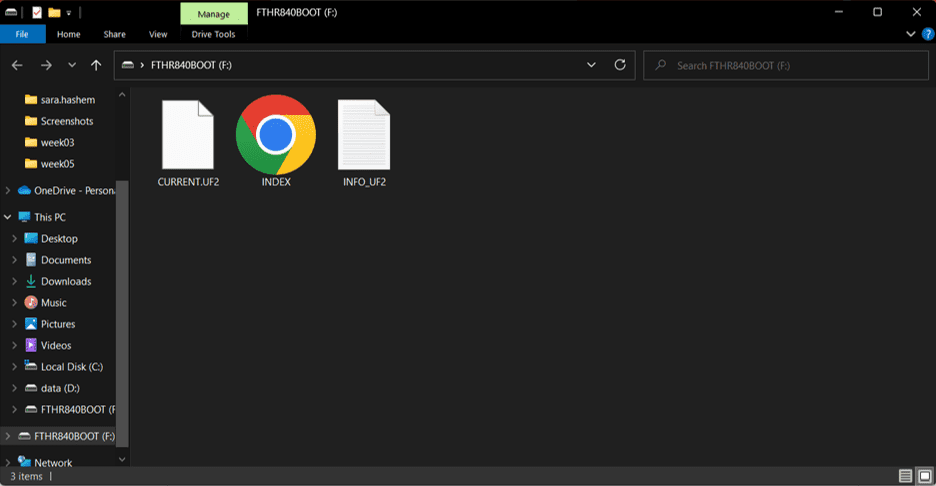
Plug in your USB to the computer, a folder should appear
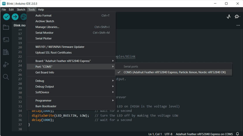
To connect your board, go to boards and choose Express
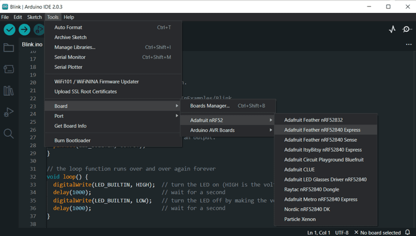
You will also need to go to Port and choose your AdaFruit
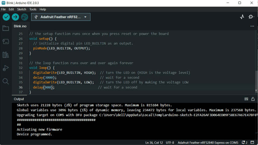
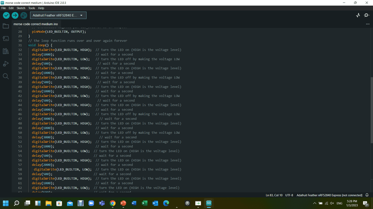
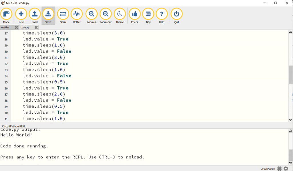
Now once you make sure it's connected, go ahead and change the values, 3000 means 3 seconds, I tried to change the values as well as copying the lines and repeating the blinking, the result was that the board plays it in an organized matter from top to bottom and then it makes a loop.


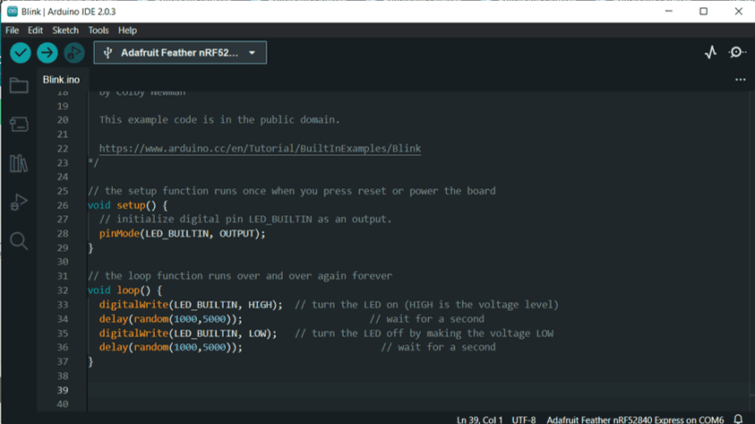
there is a code specialized in making random delays, an Example is showed below:
<#includevoid setup() { Serial.begin(9600); randomSeed(analogRead(0)); } void loop() { // print a message with a random delay from 0 to 1000 milliseconds Serial.println("Ping!"); delay(random(1000)); // print a message with a random delay from 1000 to 60000 milliseconds Serial.println("Pong!"); delay(random(1000; 60000)); } }
Once you are done click Upload
For the medium mode I tried making a morse code for 1 word message and challenged my colleauges and instructor to figure it out. the word is HELP
I also recorded a video for my first morse code trial which was the letter S.
1. Downloading and working in Mu Editor software


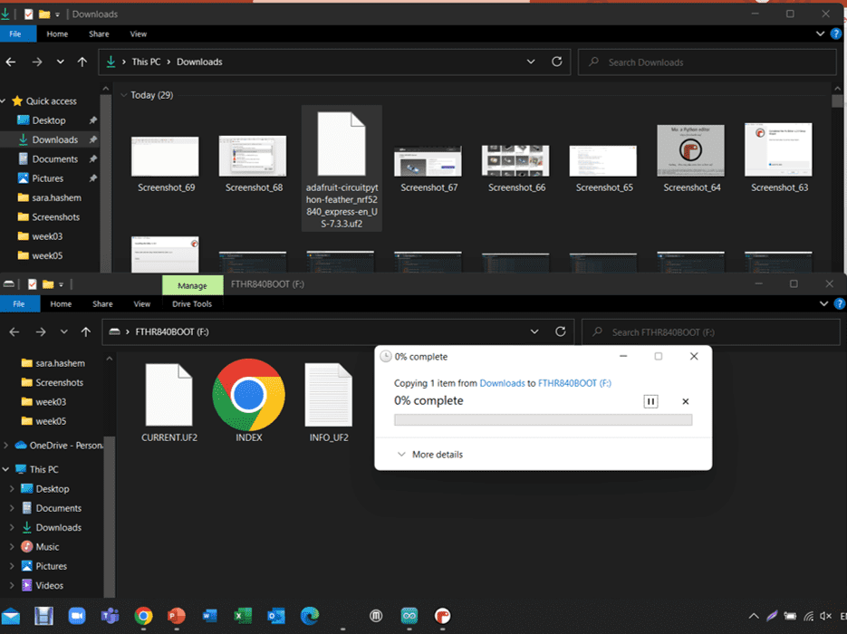
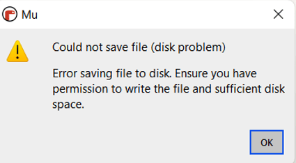
Warning! If you got this warning you can press the Reset button on your microcontroller twice.
🔗 Download Files
Arduino:
Blinking randomly
The word help
Mu Editor:
The word help blink
🔗 Resources
LearnAdafruit
🔗 Useful links
Random Delays
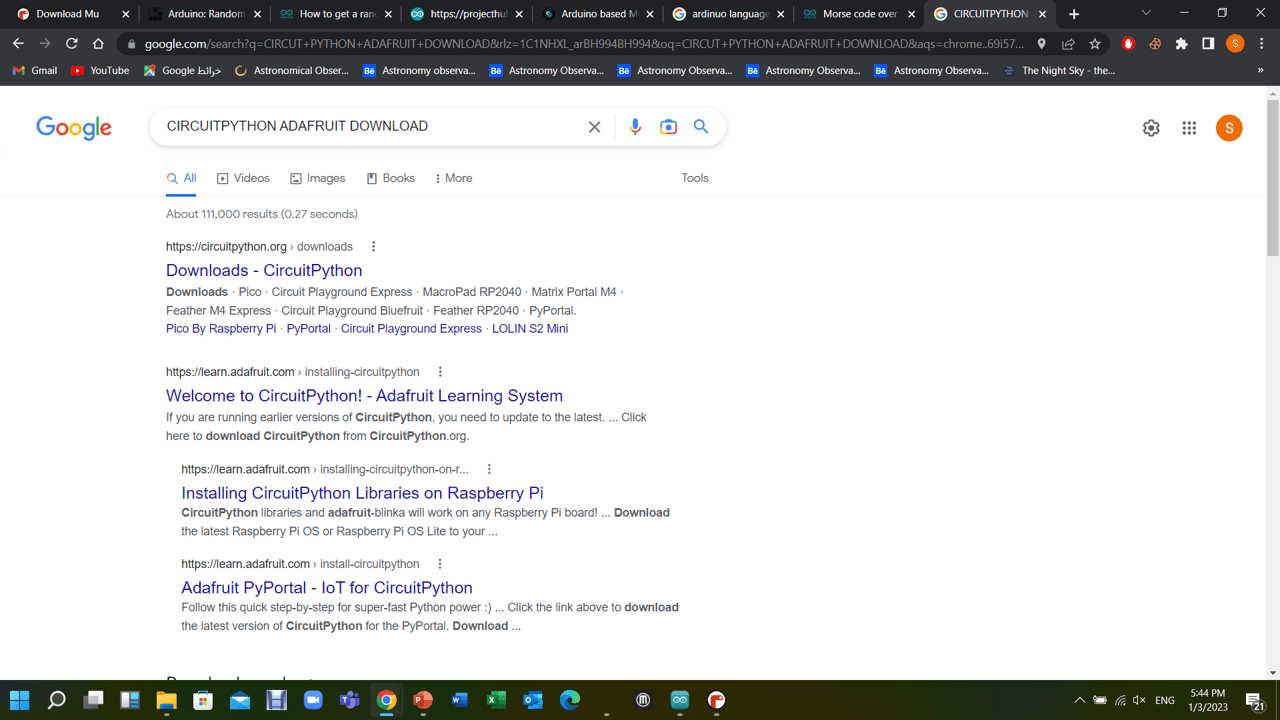
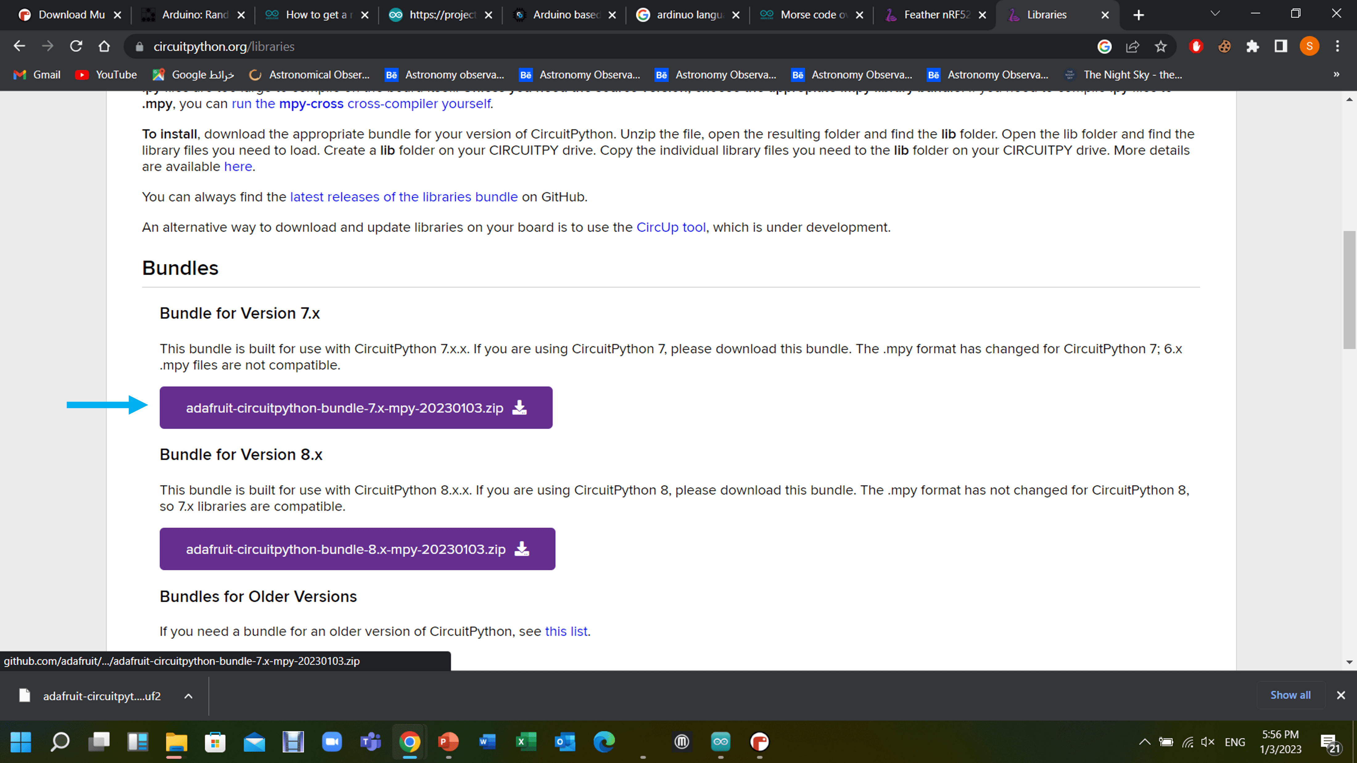
Circut Python Adafruit Download
04
Contact Me
Mobile Numberr
+973 35011840
sarahashiim18@gmail.com