4. Embedded programming
This week we learned about microcontrollers.
Initially we were grouped and given a microcontroller to research about and find some of its parameters and hopefully understand what they mean. We were given the Arduino Nano 33 IoT, we used the official Nano 33 IoT Documentation to learn about its technical specifications, you can see the results of our research here.
Next we were introduced to two different programming environment and given freedom to test out and learn more about programming microcontrollers.
Arduino IDE
To program microcontrollers we used the Arduino IDE. This program can be used to write code in C++, verify that the code is functional, and then upload the code to the microcontroller.
After downloading the software and opening it for the first time, some updates and libraries will be automatically downloaded.
To gain additional context during error debugging we tick two options from File -> Preferences:

To program a board in this IDE, you must select it. After connecting your board through USB it may automatically be identified, if not, click on select board and search for your board name which can usually be found written on the board itself.

Some boards cannot be found by default and must be installed through the board manager:

If it is still not showing up google an installation guide for your board for Arduino IDE. This guide for the Bluefruit nRF52 Feather says to copy and paste a link into the Preferences page:

It should be available for install in board manager now, and then available for selection. When selecting the port you must also select the port it is connected to in your computer, if multiple ports are present just remove the arduino USB connection and see which one disappears.
The IDE has an option to verify the code (Tick mark) and see if it has any errors, and an option to send the code to the board (right arrow), you must use the send button to operate code on the board.

Since we are beginners a lot of code we will be using will come from existing code that we edit. The first is the blink example, that already exists in the IDE.

This example code turns on the LED for 1 second then turns it off for 1 second in a loop. To stop the light you can use the reset button on the board, the behaviour seems to differ from board to board. In the one I was using (MKR 1010 WiFi), holding the reset button on the microcontroller board stops light as long as its held, double clicking stops it permanently and also deselects the port in the IDE.
Easy Task
Blink your led but have your blink delay periods be randomized values between 1 second and 5 seconds.
To do this I simply edited the example code and included the random function in the delay.
void setup() {
  // initialize digital pin LED_BUILTIN as an output.
  pinMode(LED_BUILTIN, OUTPUT);
}

// the loop function runs over and over again forever
void loop() {
  digitalWrite(LED_BUILTIN, HIGH);  // turn the LED on (HIGH is the voltage level)
  delay(random(1000, 5000));                      // wait for a second
  digitalWrite(LED_BUILTIN, LOW);   // turn the LED off by making the voltage LOW
  delay(random(1000, 5000));                      // wait for a second
}
Medium Task
pre code your microcontroller to send a Morse code 1 word message and challenge a friend, family member, your colleagues or your instructor to figure it out.
Refer to this sheet for Morse code translation:

I used 10 seconds light off as the gap after the word has ended.
void setup() {
  // initialize digital pin LED_BUILTIN as an output.
  pinMode(LED_BUILTIN, OUTPUT);
}

// the loop function runs over and over again forever
void loop() {
  // H
  digitalWrite(LED_BUILTIN, HIGH);
  delay(1000);
  digitalWrite(LED_BUILTIN, LOW);
  delay(500);
  digitalWrite(LED_BUILTIN, HIGH);
  delay(1000);
  digitalWrite(LED_BUILTIN, LOW);
  delay(500);
  digitalWrite(LED_BUILTIN, HIGH);
  delay(1000);
  digitalWrite(LED_BUILTIN, LOW);
  delay(500);
  digitalWrite(LED_BUILTIN, HIGH);
  delay(1000);
  digitalWrite(LED_BUILTIN, LOW);
  delay(3000);
  // E
  digitalWrite(LED_BUILTIN, HIGH);
  delay(1000);
  digitalWrite(LED_BUILTIN, LOW);
  delay(3000);
  // L
  digitalWrite(LED_BUILTIN, HIGH);
  delay(1000);
  digitalWrite(LED_BUILTIN, LOW);
  delay(500);
  digitalWrite(LED_BUILTIN, HIGH);
  delay(2000);
  digitalWrite(LED_BUILTIN, LOW);
  delay(500);
  digitalWrite(LED_BUILTIN, HIGH);
  delay(1000);
  digitalWrite(LED_BUILTIN, LOW);
  delay(500);
  digitalWrite(LED_BUILTIN, HIGH);
  delay(1000);
  digitalWrite(LED_BUILTIN, LOW);
  delay(3000);
  // O
  digitalWrite(LED_BUILTIN, HIGH);
  delay(2000);
  digitalWrite(LED_BUILTIN, LOW);
  delay(500);
  digitalWrite(LED_BUILTIN, HIGH);
  delay(2000);
  digitalWrite(LED_BUILTIN, LOW);
  delay(500);
  digitalWrite(LED_BUILTIN, HIGH);
  delay(2000);
  digitalWrite(LED_BUILTIN, LOW);
  delay(10000);
}
The code is long and the result takes even longer to completely show up. You can simulate the result by using the circuit designer in Tinkercad. In this case you can use the tutorial and simply edit the code then simulate to get the result.
Press start simulation and see LED light up. Can you guess the word?
Guess the Word Game
Can you guess the word?
Credit goes to Ahmed Alaali for the game.
Hard Task
you select the duration of the light being on and off while the program is running by entering it in the serial monitor. Write a code that takes the data from the serial monitor and delays by that amount of time.
This was difficult. I took code from here as reference and edited to fix some issues and fit my case which has only 1 LED.
I faced some inconsistency with the result, on some boards it worked perfectly, on others only the first input is registered and all subsequent inputs do nothing, I have no idea why.
int D; //delay is integer

void setup() {
  pinMode(LED_BUILTIN,OUTPUT);  // sets the built in LED as an output
  Serial.begin(9600); // tells the Arduino to get ready to exchange messages with the Serial Monitor at a data rate of 9600 bits per second
  D=0;  // initial delay, this makes it so that the LED is off by default
}

void loop() {
 D = Serial.parseFloat();   // takes what is input in the serial monitor and stores it as D
  D=D*1000;     // so that people input time in seconds
  while(Serial.available() ) {    // while to make it continuous and not forget D. Serial available takes input from the serial monitor when something is written.

  digitalWrite(LED_BUILTIN,HIGH);
  delay (D);

  digitalWrite(LED_BUILTIN,LOW);
  delay(500);
  }

}
Thonny
Thonny is a simple python IDE that is aimed at beginners. We use it with MicroPython to run code directly without having to compile it first, which was time consuming when dealing with the Arduino code.
MicroPython is a lean and more efficient implementation of the Python 3 programming language. It only includes a small portion of the standard python library because it is optimized to run on microcontrollers and other constrained environments.
To run MicroPython on a microcontroller we need to use a different kind of microcontroller, the one we used looks like this and based on esp32:

Compared to Arduino, ESP32 microcontrollers are faster, have more memory, and typically come with built in WiFi and Bluetooth connectivity. This enables them to operate using higher level languages such as MicroPython. However, this also makes them more complex for beginners.
The port numbers on the microcontroller can be seen on the bottom (don’t mind the large numbers on the top for now, more on this next week). There can be multiple port number for each port, if so, try out each number to find the correct one.

Notice the numbers after Io, this indicates the port numbers.
To use MicroPython on the microcontroller it has to be installed on the device itself. This can be done in Thonny by going to Tools -> Options:

Then go Interpreter, and select MicroPython (ESP32) since that is the controller we are using. Then under the port or WebRPL select the usb port that is connected to the microcontroller. Then click install or update MicroPython (esptool).

From here select ESP32, Espressif, and the latest version respectively, and click install. When installing DO NOT REMOVE THE USB.

If it is installed successfully select View -> Files:

Then on the left there should be boot.py as a MicroPython Device.

This install only needs to be done once, thereafter unless someone installs another interpreter on the microcontroller, it should remain the same.
MicroPython can be used like normal python syntax, however, because it is designed to work on small devices a lot of function are excluded by default and have to be imported. To program an LED to turn on for 2 seconds then turn off:
from machine import Pin #machine is the module and Pin is the function we are trying to import
import time #for the sleep function

Led = Pin(26,Pin.OUT)       #This means that pin number 26 is set as an output and saved as a variable called LED

Led.value(1)        #Turn on LED
time.sleep(2)       #wait 2 seconds
Led.value(0)        #Turn off LED
Careful here because things are case sensitive and indentation sensitive, also the time is in seconds unlike the Arduino which is in ms.
To make the LED blink we will need a while loop:
from machine import Pin #machine is the module and Pin is the function we are trying to import
import time #for the sleep function

Led = Pin(26,Pin.OUT)       #This means that pin number 26 is set as an output and saved as a variable called LED

while True:
    Led.value(1)        #Turn on LED
    time.sleep(2)       #wait 2 seconds
    Led.value(0)        #Turn off LED
    time.sleep(1)       #wait 2 seconds
The commands under the while loop must be indented (press tab).
We tested how low we can make the time delay. This is 0.05 seconds.
We were given an RGB LED, with this can mix the three colors but are unable control the intensity of which color. This type of light has three inputs and so can only be used with ports that have three port numbers, to find out which number is for each color you have to experiment with turning each port on and off.
This code shows the results of mixing each two colors:
from machine import Pin
import time

Ledred = Pin(17,Pin.OUT)

Ledblue = Pin(19,Pin.OUT)

Ledgreen = Pin(18,Pin.OUT)

while True:
    Ledred.value(1)
    Ledblue.value(1)
    time.sleep(1)
    Ledred.value(0)
    Ledblue.value(0)

    Ledgreen.value(1)
    Ledblue.value(1)
    time.sleep(1)
    Ledgreen.value(0)
    Ledblue.value(0)

    Ledgreen.value(1)
    Ledred.value(1)
    time.sleep(1)
    Ledgreen.value(0)
    Ledred.value(0)
This code simulates a traffic light:
from machine import Pin
import time

RedLed = Pin(12,Pin.OUT)
YellowLed = Pin(13,Pin.OUT)
GreenLed = Pin(14,Pin.OUT)

while True:
    RedLed.value(1)
    time.sleep(5)
    RedLed.value(0)

    YellowLed.value(1)
    time.sleep(1)
    YellowLed.value(0)

    GreenLed.value(1)
    time.sleep(5)
    GreenLed.value(0)
Additionally, we were able to code a button as an input, and I used it to control a fan. Initially, the fan is on and the button is held to turn it off, I wrote this code to use the button to turn on the fan while it is off by default:
from machine import Pin
import time

Button = Pin(5,Pin.IN)
Fan = Pin(16,Pin.OUT)

while True:
    if button.value() == True:
        LED.value(0)

    else:
        LED.value(1)
Using Elegoo Super Starter Kit
I bought the Elegoo Super Starter Kit from Amazon to practice electronics prior to joining FabLab Bahrain, so I was glad I had the opportunity to use it. The kit itself comes with an Arduino Uno and some electronic components to make circuits as well as a Tutorial with some code and libraries to operate these circuits. I followed to guide for wiring the circuits (I have no idea what I was doing), and then used the code that comes with the kit. Using this code I was able to operate several devices and understand how to use them in the context of Arduino IDE. And while it is true that I did not completely rely on myself to write the code, I was able to understand the code works and how to manipulate it to fit my needs.
Stepper motor with IR Remote
This code was used to operate a stepper motor in clockwise and anti-clockwise direction with the use of an IR remote:
//www.elegoo.com
//2023.05.06

#include "Stepper.h"
#include "IRremote.h"

/*----- Variables, Pins -----*/
#define STEPS  32   // Number of steps per revolution of Internal shaft
int  Steps2Take;  // 2048 = 1 Revolution
int receiver = 12; // Signal Pin of IR receiver to Arduino Digital Pin 12

/*-----( Declare objects )-----*/
// Setup of proper sequencing for Motor Driver Pins
// In1, In2, In3, In4 in the sequence 1-3-2-4

Stepper small_stepper(STEPS, 8, 10, 9, 11);
IRrecv irrecv(receiver);    // create instance of 'irrecv'
uint32_t last_decodedRawData = 0;//vairable uses to store the last decodedRawData

void setup()
{
  irrecv.enableIRIn(); // Start the receiver
}

void loop()
{
  if (irrecv.decode()) // have we received an IR signal?
  {
    // Check if it is a repeat IR code
    if (irrecv.decodedIRData.flags)
    {
      //set the current decodedRawData to the last decodedRawData
      irrecv.decodedIRData.decodedRawData = last_decodedRawData;
    }
    switch (irrecv.decodedIRData.decodedRawData)
    {

      case 0xB946FF00: // VOL+ button pressed
        small_stepper.setSpeed(600); //Max seems to be 500
        Steps2Take  =  -2048;  // Rotate CW
        small_stepper.step(Steps2Take);
        delay(2000);
        break;

      case 0xEA15FF00: // VOL- button pressed
        small_stepper.setSpeed(500);
        Steps2Take  =  2048;  // Rotate CCW
        small_stepper.step(Steps2Take);
        delay(2000);
        break;

    }
    //store the last decodedRawData
    last_decodedRawData = irrecv.decodedIRData.decodedRawData;
    irrecv.resume(); // receive the next value
    digitalWrite(8, LOW);
    digitalWrite(9, LOW);
    digitalWrite(10, LOW);
    digitalWrite(11, LOW);
  }

}/* --end main loop -- */
I am able to understand some of the code, and was able to identify the code that was used to interface between the devices.
Using LCD Screen
The kit comes with an LCD screen with 16 columns and 2 rows.
The following code is used to display Hello, World! and a seconds counter on the bottom row:
//www.elegoo.com
//2016.12.9

/*
  LiquidCrystal Library - Hello World

 Demonstrates the use a 16x2 LCD display.  The LiquidCrystal
 library works with all LCD displays that are compatible with the
 Hitachi HD44780 driver. There are many of them out there, and you
 can usually tell them by the 16-pin interface.

 Library originally added 18 Apr 2008
 by David A. Mellis
 library modified 5 Jul 2009
 by Limor Fried (http://www.ladyada.net)
 example added 9 Jul 2009
 by Tom Igoe
 modified 22 Nov 2010
 by Tom Igoe

 This example code is in the public domain.

 http://www.arduino.cc/en/Tutorial/LiquidCrystal
 */

// include the library code:
#include <LiquidCrystal.h>

// initialize the library with the numbers of the interface pins
LiquidCrystal lcd(7, 8, 9, 10, 11, 12);

void setup() {
  // set up the LCD's number of columns and rows:
  lcd.begin(16, 2);
  // Print a message to the LCD.
  lcd.print("Hello, World!");
}

void loop() {
  // set the cursor to column 0, line 1
  // (note: line 1 is the second row, since counting begins with 0):
  lcd.setCursor(0, 1);
  // print the number of seconds since reset:
  lcd.print(millis() / 1000);
}
The wiring is a mess since the screen needs so many connections:
Using I2C LCD module
To simplify the connection the LCD screen needs, an I2C module can be added. This module reduces the number of pins needed to only 2 I2C compatible pins. To find if and where my microcontroller has these pins I looked here. My Arduino UNO R3 has 2 I2C pins located at Analog Pin 4 for SDA and Analog Pin 5 for SCL.
Inter-Integrated Circuit (I2C) is a widely used communication protocol for connecting controller devices to target devices. It uses two wires for serial communication, one is the Serial Data Line (SDA), and the other is the Serial Clock Line (SCL).
I connected the I2C module to the LCD using the breadboard as shown:

Because of how breadboards work, the pins on the LCD are all connected to the I2C module’s pins facing them.

I then connected the I2C to the Arduino like shown:

Credit to this video by Tronics lk for the help and the following code.
To proceed you must find the address of the I2C device, this can be done by running this code after you have completed the circuit connections:
#include <Wire.h>
void setup()
{
Wire.begin();
Serial.begin(9600);
Serial.println("\nI2C Scanner");
}
void loop()
{
byte error, address;
int Devices;
Serial.println("Scanning...");
Devices = 0;
for(address = 1; address < 127; address++ )
{

Wire.beginTransmission(address);
error = Wire.endTransmission();
if (error == 0)
{
Serial.print("I2C device found at address 0x");
if (address<16)
Serial.print("0");
Serial.print(address,HEX);
Serial.println("  !");
Devices++;
}
else if (error==4)
{
Serial.print("Unknown error at address 0x");
if (address<16)
Serial.print("0");
Serial.println(address,HEX);
}
}
if (Devices == 0)
Serial.println("No I2C devices found\n");
else
Serial.println("done\n");
delay(5000);
}
The address of the module I am using is 0x27.
Finally, I used the following code which was modified based on this code.
// |———————————————————————————————————————————————————————|
// | made by Arduino_uno_guy 11/13/2019 |
// | https://create.arduino.cc/projecthub/arduino_uno_guy|
// |———————————————————————————————————————————————————————|
#include <LiquidCrystal_I2C.h> //got it from here https://www.arduino.cc/reference/en/libraries/liquidcrystal-i2c/
#include <Wire.h> //built in
//initialize the liquid crystal library
//the first parameter is the I2C address
//the second parameter is how many rows are on your screen
//the third parameter is how many columns are on your screen
LiquidCrystal_I2C lcd(0x27, 16, 2);
void setup() {
//initialize lcd screen. screen messes up without this
lcd.init();
// turn on the backlight
lcd.backlight();
// Print Hello, World
lcd.print("Hello, World!");
}
void loop() {
//wait for a second
delay(1000);
// set the cursor to column 0, line 1
// (note: line 1 is the second row, since counting begins with 0):
lcd.setCursor(0, 1);
// print the number of seconds since reset:
lcd.print(millis() / 1000);
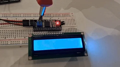
}
The result looks like this:
The brightness can be adjusted by using a screw on the built in potentiometer. Credit goes to Hassan Mandeel.
 .
.