7. 3D Printing and Scanning
Group Work
What is 3D printing?
3D printing is an additive manufacturing technique that usually involves adding material layer-by-layer based on a digital model.
- Additive manufacturing is the process of creating a physical object by adding material.
- Subtractive manufacturing is the process of creating an object by removing or carving out material.
Types of 3D printing
There are different technologies and processes used in 3D printing.
Fused Deposition Modeling (FDM)
Also known as Fused Filament Fabrication (FFF). This works by having the printer expel a plastic fiber layer-by-layer to form the object. It is the one we will be using in Fab Lab Bahrain.

STEREOLITHOGRAPHY (SLA)
The world’s first 3D printing technology, invented in 1986. It works by using Vat Polymerization, where an ultraviolet laser traces the cross-section of the desired object onto a photosensitive polymer resin, this results in the resin solidifying in the shape of the object layer-by-layer. It is considered very accurate and relatively fast.

Specific laser sintering (SLS)
This method uses a high power laser to fuse (sinter) small particles of powder into a single solid mass in the desired shape. This is done layer-by-layer with the power bed being lowered after each layer and a roller filling the bed with more powder.

Multi Jet Fusion (MJF)
This method operates similarly to SLS, however, instead of a laser, it uses a fusing agent with added heat. This means it can produce parts with less waste, but due to the cost of the fusing agents it tends to be more expensive.
Below is the schematic of an MJF printer, specifically, the HP Jet Fusion 3D 4200 (it costs $168,000!!!):

Volumetric 3D Printing
This type of 3D printing is special because it does not apply material layer-by-layer, instead, light images based on the desired object are projected into a transparent liquid resin, the light must be continuously applied from various angles in order to utilize their intersection points to rapidly solidify the resin. This technology is still in its infancy, and it requires a special resin material that can cure rapidly and accurately under the provided conditions, however, due to it not needing to work layer-by-layer, it can create objects in a very short time.
Types of 3D Printing Filaments
There many different types of Filaments that can be used with FDM, with each one having different optimal temperatures and properties, below are some:
Please note that food safe materials are considered as such because they are inert and non-toxic, however, they still may not be safe because they may contain dyes, may deform when heated, or may have otherwise come in contact with other materials and become contaminated. Furthermore, 3D printed objects tend to be porous, this nature is non food safe by default because it can harbour harmful substances, hence, to make it safe it must be subjected to post processing to make it scratch resistance, non-absorbent, and non-porous in addition to being sterilized.
PLA
Polylactic Acid (PLA) is made from organic materials that do not contain petroleum. It is typically used for low-cost, low-function parts because it is easy to use but is brittle and cannot withstand harsh conditions. It is also considered biodegradable. It is available in Fab Lab Bahrain.
There is an enhanced version called Hyper PLA that is tougher and stronger than normal PLA.
| Tensile Strength | Print Temperature | Print Bed Temperature |
|---|---|---|
| 65 MPa | 130 to 180°C | 50°C |
PETG
Polyethylene terephthalate glycol-modified (PETG) is a modified variant of PET. It is highly durable, UV resistant, warp resistant, and food safe if sterilized with Ethylene Oxide gas (EtO). It is available in Fab Lab Bahrain.
| Tensile Strength | Print Temperature | Print Bed Temperature |
|---|---|---|
| 53 MPa | 230 to 250°C | 75 to 90°C |
ABS
Acrylonitrile Butadiene Styrene (ABS) needs high temperatures for printing, however, it can warp during printing. It is known for its durability, impact resistant, and wear and tear resistance.
| Tensile Strength | Print Temperature | Print Bed Temperature |
|---|---|---|
| 40 MPa | 220 to 250°C | 95 to 110°C |
Material Comparison Table
Below is a table showing properties for common 3D printing filaments:

Slicing
Since FDM 3D printing is done layer-by-layer based on a 3D model, there needs to be a translation layer to convert the project from a standard 3D model to the needed layer-by-layer instructions, this is what a slicing software is responsible for.
Slicing refers to dividing a 3D model (typically a .stl file) into individual layers. Slicing software also consider the optimal method of printing these layers to achieve the best result in terms of strength and finish, while taking up the least amount of time.

The slicing softwares converts these instruction obtained from the original 3D model into g-code. G-code is a programming language used in CNC and 3D printing. It includes instruction telling the machine where to move, how fast to move, and which path to follow.
During the slicing process, the software also takes into account some parameters that can be controlled based on needs:
Layer Height

This refers to the thickness of the individual layers extruded by the printer. This affects the product’s quality by determining its vertical resolution. Thinner layers also take longer to print.

Layer heights can range from 1mm to 5mm, however, around 0.15mm gives the best result in terms of quality and time needed, while also resulting in high product strength due to minimal gaps.
You can use thicker layer heights for large models that do not require much detail, but in general, you should not exceed a layer height equal to 80% of the nozzle diameter.
Extrusion Width

Also known as line width. It refers to how wide the line of material that is printed is. This affects the product’s quality by determining its horizontal resolution. It is typically expressed in percentages with respect to the nozzle diameter. For a nozzle of 0.4mm diameter, line width of up to 140% can still give good quality prints, any more and the quality suffers.
Using wider line width does take less time to print.
Additionally, having wider lines results in higher product strength due to the filament being pushed stronger to spread out further from the nozzle. However, you need to be careful when increasing line width, as it results in more material being extruded, thereby increasing the load on the filament heater and the fan.
Extrusion Multiplier
Shells
Also known as perimeters. These are the outer layers that form the outer walls of a printed object.

These have a great influence on the product’s strength. In most cases, to get better product’s strength, it is better to change this to 3 shells rather than increasing the infill. Increasing it beyond 3 shells may be inefficient since it uses more material than infill.
Infills
Because solid parts are an inefficient use of materials, 3D printing technologies employ infills. Infill is the pattern of extruded material inside the object to give it strength while lowering its weight.
Because infill patterns are a mixture of solid material and empty space, their density is important, this is because it represents the ratio between the amount of material extruded and empty space. Higher infill density can give higher strength, but it also increase the product’s weight and printing time.

There are different pattens in which the infill can be extruded. Each slicing software has some of its own patterns. Some of the common patterns in most software can be seen below:

In Ultimaker Cura, the patterns each have their own advantages, the ones that are the best in a certain category:
| Category | Best Patterns |
|---|---|
| Print speed | Zig-zag, Lines, Lightning |
| Least amount of filament | Lightning |
| Toughness | Gyroid |
| Stiffness | Tri-hexagon, Cubic |
| Strength by weight and printing time | Cubic Subdivision |
| Strength in vertical direction | Grid |
| Strength in horizontal directions | Tri-hexagon |
| Strength at 100% density | Concentric |
| Flexibility | Cross 3D |
| Top surface quality | Zig-zag, Grid |
Supports
3D printing allows for the creation of complex shapes, however, it still has to obey the laws of physics. Since FDM printing works by printing the object layer-by-layer, each layer must have something underneath it to support it.

When the desired object has some geometry with nothing under it (overhanging), support structures are used. This is important because if you try to print these parts with no supports, they will be printed floating in the air and will likely droop and sag because they have nothing supporting them and they have not solidified enough in order to support their own weight.

Supports are added to prevent sagging of overhanging parts. The degree of inclination at which sagging occurs can depend on the filament, print speed and temperature, fan speed, etc. However it is generally recommended to add supports to structures inclined at an angle greater than 45°.

Since supports need to be added to all overhanging parts of an object, this can be intrusive, since this also includes inside hollow objects (depending on orientation of printing) and even threads.
There are two main types of supports:

- Normal: Also known as pillar, lattice, or linear support. This consists of vertical pillars that touch the entirety of the overhang. This type is hard to remove and is more likely to damage the model.
- Tree: This support type consists of branching structures that support the overhanging parts of a model. Tree supports are easier to remove and use less material since they can change their size according to the need.
When using a printer with two extruders it is possible to have the supports be printed in a different color to help differentiate between them. It is also possible to print the supports using a different material that can dissolve which greatly simplifies support removal.
For single extruder printers, removing supports can be challenging. Here are some tips:
-
You can break off the large and exposed supports gently with your finger.
-
Use a tool to more precisely remove supports that are smaller or are harder to reach.
-
You can heat the model to soften it and make it easier to remove the supports.
-
To remove small bumps left after removing supports, or to improve the model’s surface quality, you can use sandpaper. Wet sanding with sandpaper ranging from 220 to 1200 grit is good for this.
Bridging
Bridging refers to printing a horizontal unsupported part of the model in the air between two supported parts. In essence, bridging is what supports try to remedy.
Bridging can be done properly without supports, but it needs the correct parameters:
-
Print head temperature: To print sturdy bridges, the filament must be extruded slowly to have enough time to solidify before sagging. Hence, lowering the printing temperature can be done to control the filament flow speed and time needed to solidify.
-
Fan speed (cooling rate): The filament must be cooled as fast as possible, in FDM this is done by increasing the fan speed to its limit. This is important so that the filament solidifies quickly and retains its shape before sagging. Lowering the bed temperature if the bridge is close to the bed can also help quicken solidification, however, lowering build plate temperature can lead to warping.
-
Print speed: To ensure the bottom layer of the filament has enough time to stick to the supported parts and solidify, the print speed must not be fast.

-
Bridge length: Longer bridges are harder to print correctly. To increase chances of success, try to rotate the model to get the shortest overhanging parts as possible. At a certain bridge length, it is simply not viable to print the model without supports, typically this is taken as anything longer than 10mm.

-
Filament Quality: Higher quality filaments tend to have tighter tolerances in their cross sectional area, which can improve printing. Ensuring the filament used is dry is also important because many filaments tend to absorb humidity and moisture from the air, this can cause packets of moisture to form in the print which leads to inconsistent extrusion. This can be combated by keeping the filaments sealed or stored in a dry place, or by using a filament dehydrator.

Skirts, Brims, and Rafts
The first layer of an object during 3D printing can face difficulties due to it contacting the printer bed, this can be in the form of it sticking to the bed or having a rough surface. To mitigate these issues some detachable structures can be added :

-
Skirt: A single outline surrounding the object without actually touching it. It is used to prime the extruder and establish a smooth flow of filament.
-
Brim: Layer printed on the printer bed around the object but not under it. It is used to hold down edges of an object, which can help prevent warping and help with bed adhesion. Not needed if the object has a wide base.
-
Raft: Series of layers printed on the printer bed under the object forming a detachable base. It is typically used with ABS to help with warping and bed adhesion, while also helping stabilize models with small footprints and a heavy top, it also helps create a strong foundation on which to build the upper layers. It is a good solution if the printer bed is damaged or uneven
Test Print
In Fab Lab Bahrain we currently have 2 operational 3D printing machines. We will be performing a test print using no supports in both of them in order to compare the results and process used.
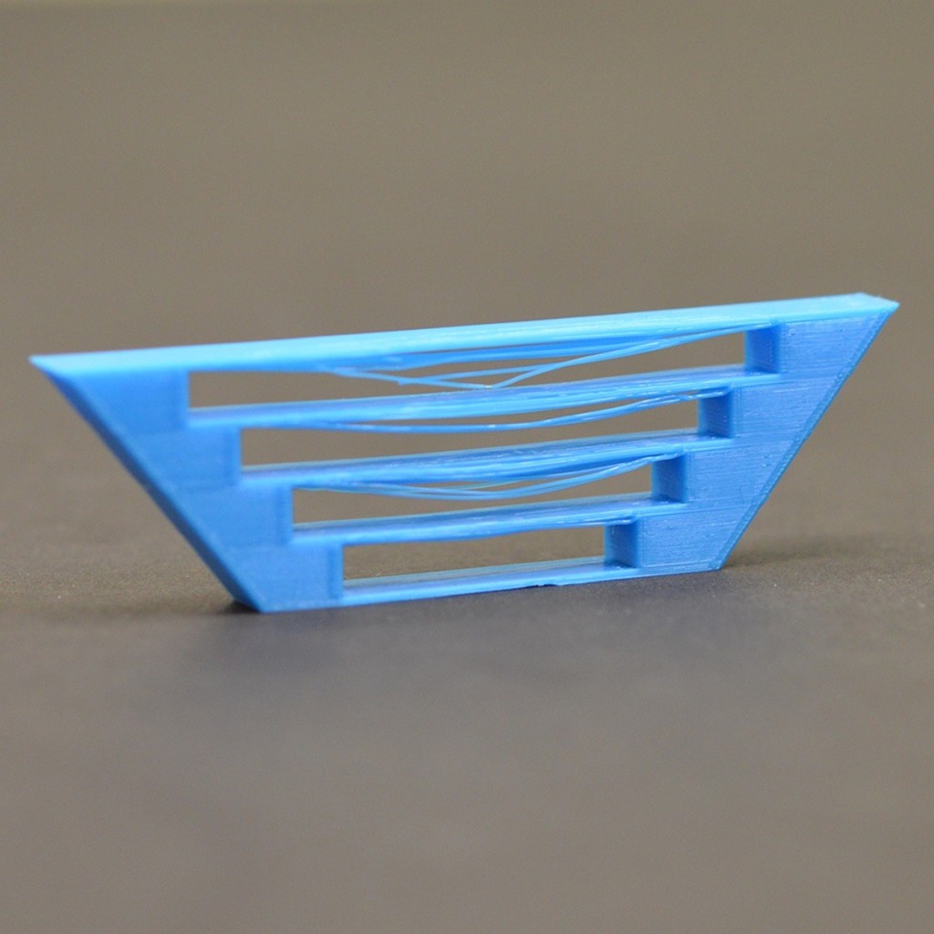
For the test model, we browsed Thingiverse and used this model to test out the printing without using supports.
You can see the steps and comparison on Ali Al Radhi’s website
Creality K1

This printer uses the Creality Print software.
Ultimaker 2+

This printer uses the UltiMaker Cura software (along with many other printers).
Comments
The results from the Creality printer were much better and even printed faster. They had strings but they were much less than the Ultimaker, and even the surface quality was better. The detail was not great on either printer, I even saw the results from the previous group and they were much better, especially the Creality which had perfectly readable numbers.
The software for both printer was easy to use, but Ultimaker Cura does have a lot more options.
Sending files to the Creality printer was easier since you could do it via WiFi, while the Ultimaker needs an SD card slot on your laptop which not everyone has.
Individual 3D Printing
I decided to use the opportunity for the individual printing to test out prototypes for our final Fab Lab project. You can read more about the project here
I designed the pill dispensing mechanism we saw in this video.
First Attempt
At first I designed the top and bottom rotating disks and the male gear.
Bottom Rotating Disk
I made the bottom rotating disk by making a solid disk of 10mm depth and 70mm diameter, and then cutting a slot on the side for a pill to fit. I made the slot size based on a tic tac’s dimensions with an extra tolerance of slightly over 1mm (assuming tic tac pills have a constant diameter of 5mm):

I cut out this profile by using an offset to the edge of the rotating disk and then cutting 7mm:

I also cut out through-all holes for the top rotating disk to attach to the bottom one. I added a 1mm fillet to remove the sharp and edge and also try to help ease the insertion.

On the bottom side I cut a hole 7mm deep and 10.5mm in diameter and added threads with SOLIDWORKS’s thread tool:


These are to hold the male gear.
In the end it looked like this:
Top Rotating Disk
For the top disk, I first sketched this profile the cross section shape and then revolved:

I then drew these ridges that should help move the pills instead of them rotating in place:

I extruded these using an offset of 5mm from where the curved part starts, and then used up to surface as the ending condition to get the smooth extrusion that matches the contours of the curve.
On the bottom, I added some legs that attach to the bottom disk. I made these 0.2mm thinner and 1mm shorter than the slots. I also added a 1.5mm fillet to strengthen their connection to the disk.

It looks like this:
Male Gear
The male gear looks like a screw. The head is a cylinder 20mm in diameter and 5mm in depth, the body is 16mm long with a diameter of 11mm, except the last 6mm are extruded as 10mm with threads. I did this to make a clear separation between the threaded and unthreaded parts to act as a stopping point when inserting it into the bottom disk.
On the head, I added some contact points that should mesh with another part called the female gear.
I made these contact points flat on one side and angled on the other, this is to make sure that the rotation only occurs in the clockwise direction and if anti-clockwise rotation happens the two gears will slip. This is because the rotating disks were designed to work only when they rotate clockwise.
To make these contact points, I first extruded this profile:

Then I added the angled bit on the part in contact when rotating anti-clockwise:

Then I simply used circular pattern on the angled bit, and trimmed the unwanted parts until this was left:
Printing
I used the Creality K1 with this black filament to print:

I printed with other people to be more efficient. The settings we used were default except we also added supports:

Result
These are the results


Overall, this print was not good. Surface finish was not nice. Slot joints were very hard to insert and remove, I even broke the pieces trying to get them in. The threads did not fit. Overall, it seemed that the making the holes the same size as the parts that would fit in them was not a smart idea. The simulated medicine pill (tic tac) also got stuck in its slot.
Second Attempt
Changes
I printed the same components but with some changes. Namely:
- I merged the two rotating disks into one piece. This was to combat the difficulty in assembling them together without breaking.
The new piece looks like this:
- I added a 2mm fillet to the male gear in the place where it broke.
- I made the threaded part’s diameter in the male gear 10mm instead of 10.5mm. This is makes the allowance between it and the disk 1mm.
The new male gear looks like this:
I printed them in the Ultimaker 2+ using black PLA filament and default slicing settings:

Results
The results were not much better. Making the disks one piece was a good idea but the quality remains bad.


Third Attempt
I used fusion instead of SOLIDWORKS to save the female gear as stl. I used this grey PLA filament and printed on the Creality printer:

Result:

Since result is really good maybe the problem of poor surface finish comes from SOLIDWORKS.
I saw this video about adjusting the stl file detail:
This video explains the stl file save settings.
The deviation affects the model surface detail, while the angle affects the accuracy of circular hole.
This video says that the optimal settings in terms of file size and model detail for 3D printing models from SOLIDWORKS is ~0.005mm Deviation with 10° Angle.
Fourth Attempt
I printed the same piece with the same filament but exported the stl from SOLIDWORKS using the recommended saving settings instead of Fusion:

The result came out good just like the Fusion test.
Final Takeaway
After I finished printing the prototypes, I tried printing a simple vortex toy on the Ultimaker. The result turned out bad just like the first two attempts.
This means that to get a good printing result I need to save a high quality stl file from SOLIDWORKS and also ensure that the filament I am using is of good quality and has not been subjected to humidity.
Additionally, to get good bed adherance for parts with a small footprint -like the sweeper arm in our project- I needed to add a brim.
This video explains some additional slicing options to try out to speed up printing while maintaining or increasing strength:
Individual 3D Scanning
We will be using our phones to scan an object to digitally make a copy. I am using an android phone, so the apps I am using may not function the same on other operating systems, even though I tried to select applications that are available on both the google play store and the apple app store.
I used different apps to test out their abilities. I decided to try to scan a 3d printed rick that was lying around in Fab Lab Bahrain in all the apps to try to get an objective comparison.
polycam

The steps are very fast and simple. As soon as I opened the app the camera opened and gave me the option to scan using multiple pictures taken manually, or just a video where the app itself takes the necessary stills:

I chose the video method and spun around the object for about a minute.
For the processing option I chose Full detail and Use Object Masking:

The upload and processing took less than 5 minutes. Here is the result:
The result looks somewhat good. The colors have been retained. I exported the model as GLTF file since that is the only free option, but it is fine since sketchfab can accept this format.
MagiScan

To scan in this app you need to simply go to the scan tab. I chose 360 scan. However, You only get 3 free scans in this app.

Scanning here gives a lot more feedback, telling you to slow down and pictures from which angles are missing.
This is a 2x speed segment from the scanning process:
Unfortunately, the results I got from this app were unsatisfactory:
Scaniverse

This app offers a lot of options for scanning and processing. I used Mesh scan type, small object scan size, and detail processing mode.
This is the result:
However, whenever I try to export the model as a 3D model in a useful file format, it looks to be corrupted.