6. Week 6: Large format CNC (computer controlled Machining)
Group Assignment (Link)
During the group assignment, I learned many things including:
1- The safety precations I must take before operating the machine (wearing safety goggles, safety shoes and ensuring my long sleeve are twisted up).
2- How to start the machine.
3- Zeroing the Z axis.
4- Setting the speed and feed-rate of the milling bit.
5- Setting whether the tool must cut on the line, inside the line or outside the line.
6- How to install the dust cover and remove it.
7- How to change the machine bit.
8- How to setup the MDF sheet on the machine for the machining process.
9- How to specify whether the machine will cut or engrave the line.
10- The most suitable cutting speed and feed rate for MDF (17000 RPM and 60 in/min).
Individual Project
We were required to design something big using the CNC machine and a MDF wood sheet.
Design guidelines/constraints:
1-The design must be press fit and utilizes wood joints for assembly. Use of mechanical fasteners is not allowed.
2-The product must be big (at least 0.75m in one direction).
3-The material provided to use is a 4x8 feet MDF wood sheet with a thickness of 12 mm.
4-The diameter of the milling bit of the CNC machine is 6 mm. Thus, it cannot machine anything smaller than 6 mm.
Design Ideas
While thinking about what to design, I have had many ideas:
1-Tensegrity Table

This type of tables utilizes chains/cables to connect the top and bottom half of the table together. The legs of the table experience compressions force while the chains undergo tension forces which create a force equilibriam resulting in the top of the table being afloat.I have always been curious about this type of table and I wanted to create one. Since I had the materials and opportunity to do that, I thought It would be a great idea to fabricate it using the CNC machine.
2-Moon
I had the idea of creating a half sphere moon and engraving the curators of the moon on the surface however, due to the large number of people in the CNC group and the limited time, that was not possible.
3-Saturn

Then, I had the idea of creating the planet Saturn using a slicing technique to create sphere and create rings around the plant. The image above is a prototype I have created to see how it would look.
3D Modelling
I started creating the design by sketching a frame.

I extruded the two layers of the frame by 12 mm each.

I sketched the diameter of the planet and created two planes to create the planet and its rings at an angle.


I sketched the layers of the planet using the linear pattern feature. The planet half sphere will consist of 21 layers.

After that, I used the revolve feature to create the planet half sphere.

Then, I proceeded to create the planet rings by creating the sketch.

I extruded the ring I sketched.

After that, I proceeded to extruded the smaller inner ring.


I mirrored the ring to create the upper inner ring.

Then, I proceeded to create the joints for the planet slices.


After that, I created the holes in the frame by utilizing the convert entity feature so that the planet and the rings can connect to it.


I created holes in both layers of the frame to be able to connect them together using joints.


Then, I created pieces to go in the holes to connect the frame layers together.

I wanted to add the name of the planet on the frame so, I created a sketch and added the text.

Then, I used the extruded cut feature to create the engraving with a depth of 6 mm.

After that, I created support brackets on each side to reduce the sagging of the rings.


Final Design


I lined up all of the parts in a two sheets (using the move/copy feature) to prepare them for the CNC and laser cutting machine.
For CNC

For Laser Cutter

CNC Preparation
CNC cutting process steps:
1-Turning the power button to start the machine (red button) and the key to engage the spindle.

2-Resetting the machine by pressing the blue button for 3 seconds.

3-Opening the ShopBot software and moving the z-axis up so we can insert the wood sheet on the machine.

4-Vacuuming the surface of the machine to remove any debris that will affect the flatness of the wooden sheet.

5-Inserting the wooden sheet and ensuring it is flush with the sacrifice sheet.

6- Inserting screws into the wood plank to ensure it will not move during the cutting process.

7- Zeroing the Z axis by ground the ground clamp and inserting the metal plate below the drill bit. Then, pressing the button to bring the z axis down.


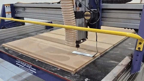
8- Returning the “zeroing” equipment to their place.

9-Opening the knob to bring the dust collector bracket down.

10- Inserting the dust collector attachment.

11-Connecting the tube to the attachment and raising the attachment up to lock it in place.

12-Opening VCarve Pro and defining the page dimensions as the wooden sheet.

13-Creating a clearance rectangle by offsetting the page by 20 mm.

14-Importing the DXF file by going to File-> Import.


14-For some reason, when I exported my file, all of my sketches were considered open vectors. So, I had to turn them into closed vector.


15-Adding dog bone and T-bone to the corners of the joints.


16-Going to 2D tool path -> cutting depth and making 0 mm as the starting depth and 13 mm as the cut depth. This is to ensure that the tool cuts through the wood completely. Also, going to the passes option and specifying the depth of pass 1 as 6.5 mm. This will make the machine take two passes to cut the wood.


17- going to the tool option and specifying the diameter of the tool as 6 mm.

18-Specifying the engraving depth of the word Saturn as 6 mm and specifying the cutting path as on the line, inside the line and outside the line depending on the requirement.


19- Saving the toolpath


20- Calculating the time taken and starting the cutting process.
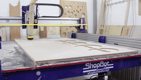
CNC Cutting Process
Laser Cutting
I used the laser cutter to create the rings and the letters.
Assembly of CNC Parts


Painting Process
I started the painting process of Saturn by sanding off all the surfaces that will be painted and applying a coat of primer. After the primer dried off, I sanded the surfaces again and applied a second coat.

Then, I sanded off the surfaces and again and masked off the sphere to paint the background. I spray painted the background black and waited for it to dry. Then, I used other colors to create the small planets and stars.

After I was finished with the background, I masked it off and began painting the planet’s sphere. I spray painted each layer of the planet manually and I used masking tape to make sure that the “overspray” does not reach them.


Then, I applied wood stain on the frame and I assembled it with the planet.

Electronics
I placed an LED strip over the frame and used an Arduino to power it. I drilled a hole in the background and inserted the wires there to be able to screw the Arduino to the rear of the frame.
Code used:
// Sequential color fade! Connect an RGB LED to the PWM pins as indicated
// Public domain, enjoy!

#define REDPIN 6
#define GREENPIN 5
#define BLUEPIN 3

#define FADESPEED 10   // Increase this value to slow down the fade

void setup() {
  pinMode(REDPIN, OUTPUT);
  pinMode(GREENPIN, OUTPUT);
  pinMode(BLUEPIN, OUTPUT);
}

void loop() {
  // Fade in and out each color sequentially

  // Fadz Red up to full brightness and down to off
  for (int r = 0; r < 256; r++) {
    analogWrite(REDPIN, r);
    delay(FADESPEED);
  }
  for (int r = 255; r >= 0; r--) {
    analogWrite(REDPIN, r);
    delay(FADESPEED);
  }

  // Fade Green up to full brightness and down to off
  for (int g = 0; g < 256; g++) {
    analogWrite(GREENPIN, g);
    delay(FADESPEED);
  }
  for (int g = 255; g >= 0; g--) {
    analogWrite(GREENPIN, g);
    delay(FADESPEED);
  }

  // Fade Blue up to full brightness and down to off
  for (int b = 0; b < 256; b++) {
    analogWrite(BLUEPIN, b);
    delay(FADESPEED);
  }
  for (int b = 255; b >= 0; b--) {
    analogWrite(BLUEPIN, b);
    delay(FADESPEED);
  }
}
Final Result


What Went Wrong
Blackout
Unfortunately, when I was cutting my design in the cnc machine, the electricity got shut off and one of my pieces (the frame) was ruined due to the machine stopping during the cutting process. However, thankfully Abdulla Altooq was generous enough to let me cut the piece again using the extra space in his wood sheet. That worked in my favor due to the new frame being made from plywood which allowed me to get a nice finish using the wood stain.
CNC Bit Limitation
I cut the planet rings out of 3 mm acrylic but the CNC machine’s bit is 6 mm in diameter which made my ring’s joints too wide. However, they still fit tight. To make them stay in place and not sag down, I designed a bracket to hold all three rings in place. While the bracket did not limit the movement, it certainly helped. The sagging down issue was also due to the fact the rings are sticking out a lot in the air which causes a large moment on them.

Final Notes
Huge thanks to Faisal Alhammadi, Noor and Yaqoob for helping me in the painting process, Abdulghafoor and Faisal for helping me with the CNC cutting process, Faisal Fathi for editing the code of the LEDs, Abdulla Altooq for letting me use a part of his wood sheet and my brother Mohsin for giving me the funds to by the paint.
This project took me 3 weeks to complete but, the final result was worth it!
