Computer Controlled cutting B
Group assignment requirements
The group assignment for this week is the following:
- Characterize your lasercutter’s focus, power, speed, rate, kerf, joint clearance and types.
- Document your work on the group work page and reflect on your individual page what you learned
Laser cutting machine specs

Describe/list the available features and key settings of your laser cutter.
Machine name:
Machine max power in Watts:
Machine bed size (work area):
Machine type (CO2 or fiber):
Toolpath generation software used:
Safety
Describe the safety measures around using your laser machine. Fire extinguishers, safe distance, etc
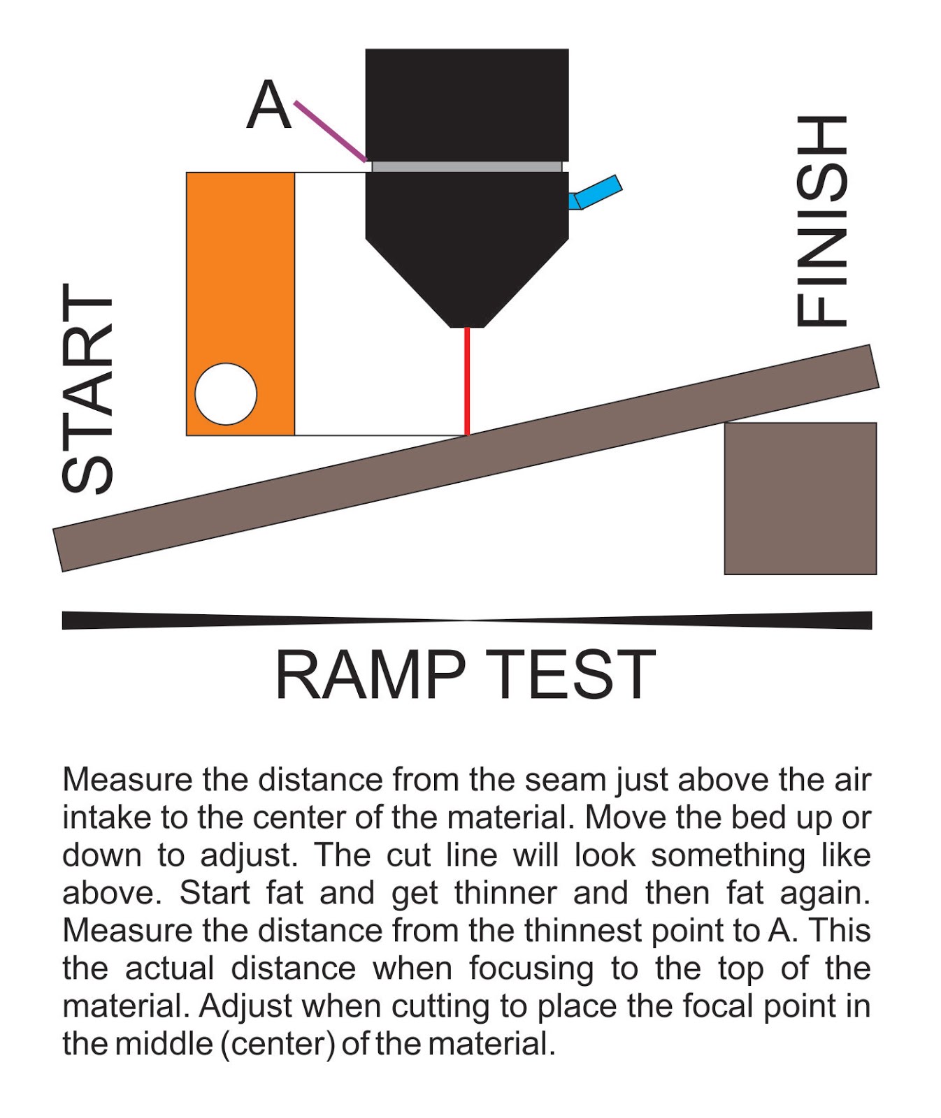
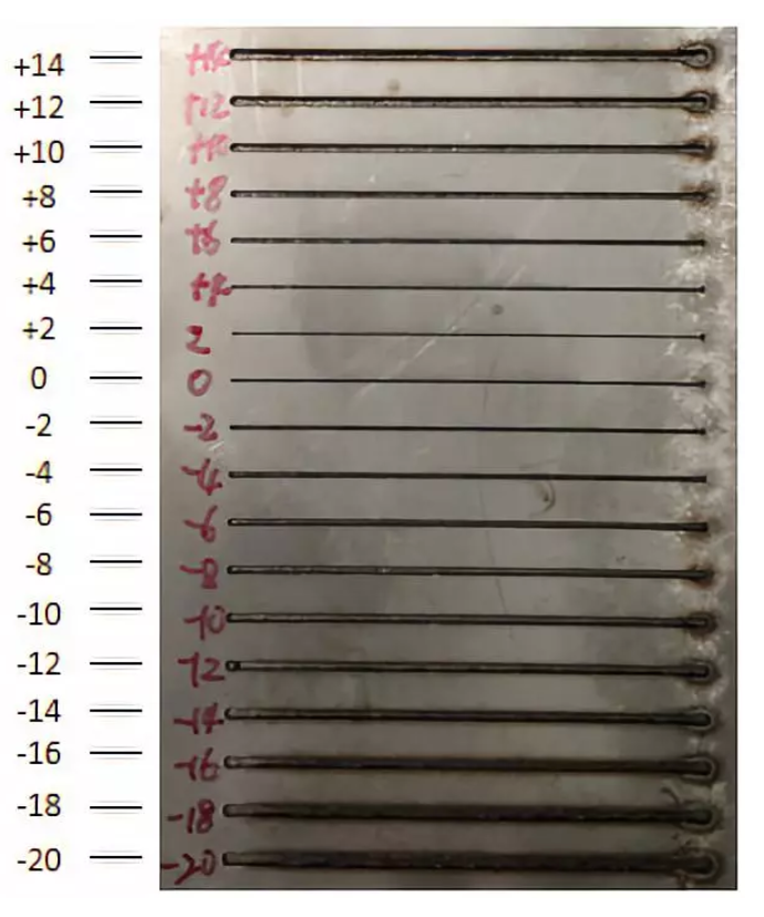
Focus
The focus position of the laser cutting machine is the relative position between the focus and the upper surface of the workpiece, based on the machined material surface.

Perform one of those 2 Focus tests, take pictures and log the results test1 test2
[describe the test]
As per the test performed, we found the optimal distance between the lens and material to get the best focus is ![distance]mm
Power and speed
make multiple small squares 2X2cm and cut them at different speeds and powers. Write on them the speed and power of each manually after cutting before taking the picture
The material being tested is [material] which is [thickness]mm thick. Multiple different speeds and powers were tested and the best values were found to be a power of [power] and a speed of [speed].
Rate
The rate at which the laser pulses or fires. For this material we used a rate of [rate]
kerf & joint clearance
Cutting kerf is the amount of material that is removed by the cutting process. This information is crucial when designing joints since the design used must account for the cutting kerf to be able to fit properly. the kerf test generator
The test performed is the comb test/kerf test. The material used has a thickness of [thickness]. The slot that worked best with the chosen speed and power settings had a thickness of [thickness] in the design.
[Material thickness] - [best fit thickness] = [answer]
Kerf = [answer] / 2 = [kerf]
Sources
The information referenced in this page was found in the following sources:
Source 1
Source 2
Source 3
Source 4