
Introduction to Computer-Aided Design
Computer-Aided Design (CAD) is to use computers to aid
in the creation, analysis, simulation and optimization of design.
CAD could be in 2D or 3D drawing depending on the project itself. 2D drawing in divided to Raster and VEctor drawing. Raster drawing is image generated of countless number of pixels. On the other hand, Vector drawing is images made of points that are connected by lines and curves.
The tree chart below shows the types of drawing and the softwares used to do each type.
In FabLab, most of the machines needs a drawing to implement it.
CAD make you express whatever in your mind as a drawing.
CAD could be in 2D or 3D drawing depending on the project itself. 2D drawing in divided to Raster and VEctor drawing. Raster drawing is image generated of countless number of pixels. On the other hand, Vector drawing is images made of points that are connected by lines and curves.
The tree chart below shows the types of drawing and the softwares used to do each type.
- Computer-Aided Design
2D Drawing
3D Drawing
As I mentioned before I have background in different 3D drawing softwares
such as AutoCad and
Inventor.
But now I have been introduced to new 3D softwares which are
Fusion360 and
OpensCad
by my instructor.
I first attended a session that talks about Fusion360 basics given by Abdullah AlBaitam.
And then downloaded the software by choosing the personal package.
Afterthat, I followed different tutorials shared by my instructor, which are discussed in the following sections.
FUSION 360 Software
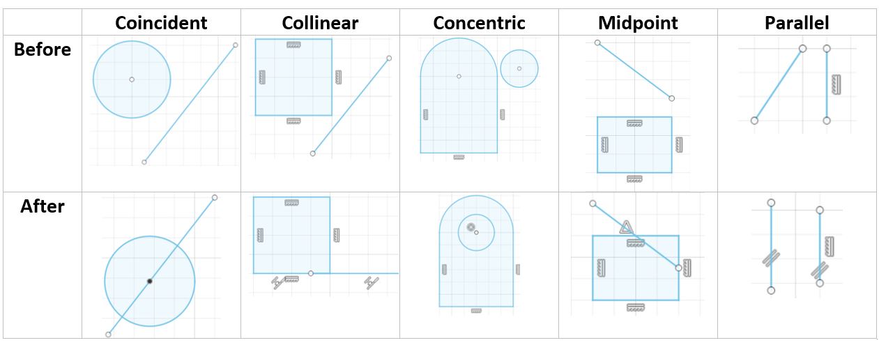
Tutorial #1. Sketch Constraints
This tutorial is important to understand the each sketch constraint option that is available in Fusion360.After watching the tutorial I tested different constraints options to understand each one.
And the image below is an example of my practice, showing the illustration before and after apply constraints.
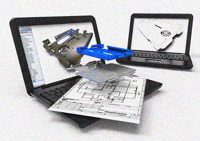
Tutorial #2. Designing a Lasercut Laptop Stand with Fusion360
This Tutorial is to be introduced to the sketching options such as:I practiced the tutorial and get the same final result as shown below.
*The 3D file of this design can be downloaded from here.
OpensCad Software
OpensCad is a software used to draw 3D objects using codes, I practiced OpensCad and was able to
draw a 3D Roller Bearing. I will explain below my steps that led to the final 3D view.
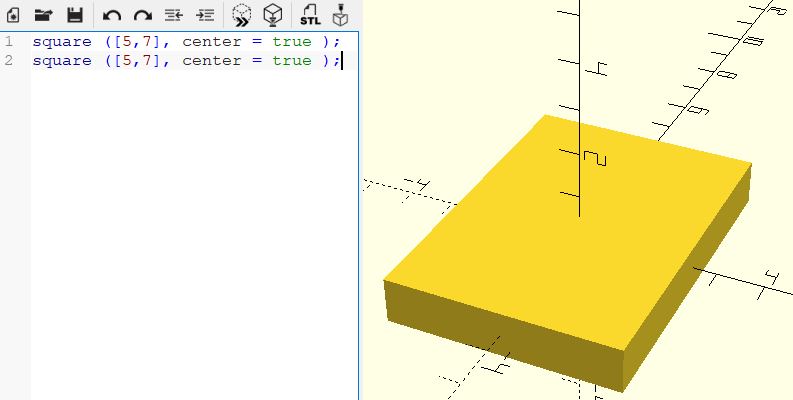
1. Drawing two sequares that are equal in dimensions.
*press preview after each step to see the result or F5
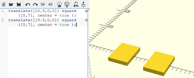
2. Moving the two squares from the center using the command translate.
*specify the coordinates in [x,y,z] directions
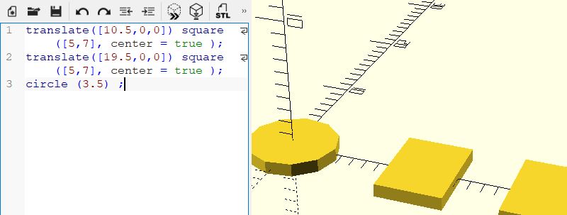
3. Draw a circle with the requiered radius.
*you will notice that the circle has edges and not smooth
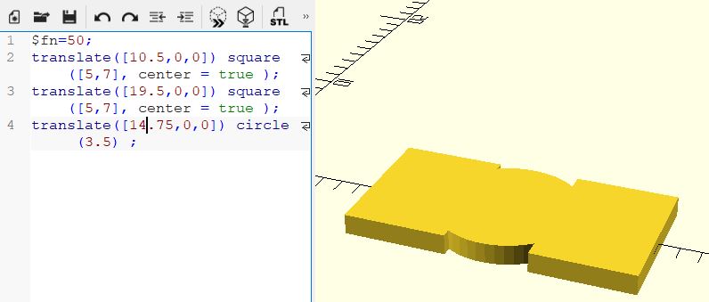
4. Use fn command in the first line to have a smoother circle, and change its position to be in the center point of the two squares.
*example: $fn=50, notice than using an number that is greater than 50 will make the circle even smoother.
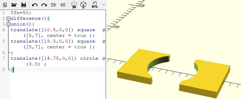
5. Use difference command to make the shape of the bearing races. Difference command works by subtracting the second object from the first one.
*use union command to deal with the two squares as one object, so that difference command will be used once.
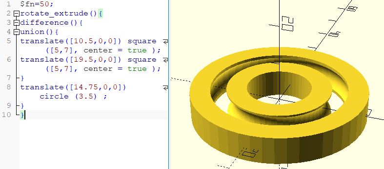
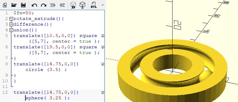
6. Use rotate and extrude comand to generate the 3D outer and inner races.
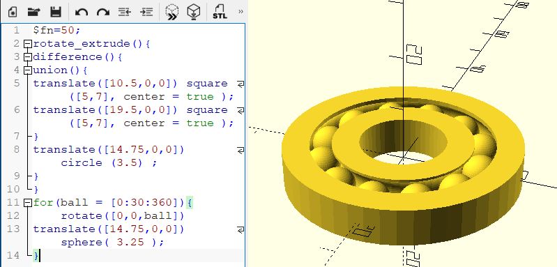
7. Draw a sphere with the required radius to generate the rolling elements of the bearing.
8. Use loop and rotate command to repeat the sphere.
*The 3D file of this design can be downloaded from here.
1. Drawing two sequares that are equal in dimensions.
*press preview after each step to see the result or F5
2. Moving the two squares from the center using the command translate.
*specify the coordinates in [x,y,z] directions
3. Draw a circle with the requiered radius.
*you will notice that the circle has edges and not smooth
4. Use fn command in the first line to have a smoother circle, and change its position to be in the center point of the two squares.
*example: $fn=50, notice than using an number that is greater than 50 will make the circle even smoother.
5. Use difference command to make the shape of the bearing races. Difference command works by subtracting the second object from the first one.
*use union command to deal with the two squares as one object, so that difference command will be used once.
6. Use rotate and extrude comand to generate the 3D outer and inner races.
7. Draw a sphere with the required radius to generate the rolling elements of the bearing.
8. Use loop and rotate command to repeat the sphere.
*The 3D file of this design can be downloaded from here.