Group Assignment

Testing the feed and speed

  • To do the group assignment we had a virtual meeting with Abdulla Fadi to see the steps of using the CNC machine.
  • The machine found in the lab is connected to a software called VCarve, this software enables you to change the speed, feed, toolpath and even do 2D drawing.
  • We first did a simple 2D drawing that contains different feed rates and different speeds.


  • As shown in the figure, at the right we will be changing the feed with a constant speed, anf then the speed will be changed while the feed is constant. We also add a Happy Face drawing to test the Pocket.


  • This Toolpaths menu is where you can setup the material to be cut and choose from different toolpaths operations.


  • As shown in the figure, the first toolpath is to cut through this dashed rectangle. We used a 2D Profile Toolpath to do this with a cutting depth of 13mm. As you can see in the tool edit window, the diameter of the tool is 3mm and we setup the speed to 14000 rpm while the feed is 120 inches/min. The tool is also set to pass 5 times over the rectangle, with increasing the depth by 3mm in each pass.


  • When we pressed OK, this warning window appeared saying that the tool will cut throught the material because the material to be cut is set up to have a thickness of 12mm while the cutting depth is set up to be 13mm. But we meant to do this to ensure that the rectangle is cut throught, and the extra 1mm will cut the sacrifice sheet found in the machine below the working material.
  • *if there is no sacrifice sheet, the tool may cut the machine and damage it.


  • Here is the toolpath preview for the first toolpath opration.


  • To cut the text in this desing, we selected pocket tool path with a depth of 2mm and we kept the speed and feed parameters the same. Pocket toolpath will simply engrave the text at a certain depth.


  • This is the toolpath preview after adding the pocket toolpath.


  • We used drilling toolpath to cut the two holes in the corners of the design with a cutting depth of 13mm. But here we changed the feed parameter to be 100 inches/min.


  • As you can see here, in these lines we will change only the feed rate for each line keeping the speed constant at 14000 rpm. We usef the 2D profile toolpath with a cutting depth of 13mm.


  • This is an example of changing the speed from 8000, 11000, 14000 and 17000 rpm with a constant feed of 60 inches/min.


  • This is the toolpath preview after setting all the toolpath operations. As you can see there is a toolpath list to arrange the operations, we left cutting the outer rectangle to the last. And this is because we want the material to stay fixed in its place to finish engraving and drilling oprations and the cut the rectangle.


  • This is the shape after operating the CNC machine.
  • Group Assignment

    Testing joint

  • Abdulla Fadi also shared with us a join test, to see what dimension difference we need to have a good fit joint.


  • As you can see in the figure, the part to be joined is having 11mm in hight, and the slots where starting from 10.95 mm and then minimizing by 0.1 mm until 10.25mm. Where 10.95mm slot is too loose and 10.25mm is impossible to fit.
  • The slot with a hight of 10.45mm fit really well and the part can not be removed by hand.
  • The width of the part is 50mm, while the slot width is 50.4mm.
  • You will notice in the corners of the slots there is a small circle, this called a Dog Bone technique applied easily from VCarve to ensure that the tool will cut the corners perfectly.


  • This figure shows the toolpath when we apply a Dog Bone technique.
  • I used this joint test as a reference to compelete my design, where I found a hight of 10.65mm is a perfect joint with a 0.35mm difference from the part.
  • Individual Assignment

    Mechanical Iris

  • My idea for a CNC machined design is a mechanical iris. Which is a mechanism that opens and close by moving a handle just like this gif below.


  • I followed a tutorial on Youtube that describes how to do a mechanical iris using Fusion360 Software.


  • To finish the mechanical iris there are three steps that I have to follow which are: design, mill and assemble.
  • I will discuss each step breifly in a seperate section.
  • Designing the Mechanical Iris

    Using Fusion360 software

  • I followed the tutorial step by step to finish all the parts, but here I made everything parametric.
  • I wanted to do my whole design parametric to be more flexible when I want to change the dimensions.


  • This is where I change the dimensions in Fusion360, solid- modify- change parameters and then press the + sign to add a new parameter.
  • As you can see in the table, I also added some equations to link one parameter to another one, for example:
  • offset = hole_diameter/2+0.05mm
  • So when I change the hole diameter, offset value will be changing accordingly.
  • My design contains three main parts as the following:

  • Part #1

  • The first part is a ring with a sliding slots as the following


  • I used a circular pattern feature found in Fusion360 to repeat the slots for 8 times.
  • You can download this part as a 3D drawing.


  • Part #2

  • This par is also a ring but with a handle to be rotated by hand. the slots in this part is also different to be suitable a slider for cylinders.


  • Here, I also used the circular pattern feature to repeat the slots. Circular pattern is important to do the exact slide with the same curve angle.


  • Part #3

  • This is the last part of the design, that I will be produced using the CNC machine for 8 times to be fixed in the 8 slots.


  • As you can see there is a cylinder and a rectangular extrude to be joined to the part as shown in this side view.


  • The cylinder will be inserted in part 2 to slide, while the rectangle will be inserted in part 1 to slide in the slots.
  • Here is the 3D drawing of the part.


  • This is the model below containing all the parts.

  • Before We Start

    What We Need to Know About the CNC Machine

  • Before we start operating the CNC machine there are some tips that we should know, to ensure having a perfect milling process.


  • This red buttons are used in case of emergency, to fully stop the machine.


  • This key is to open the machine.


  • This is the vacuum machine that should be operated before the milling opration start using the key in the picture. The vacuum machine is important to remove all the waste material from cutting and have a clean output.


  • The sheet should be fixed over the sacrifice sheet using a drill and pin, to ensure that the sheet is fixed in its place during the milling process.
  • Milling the Mechanical Iris

    Uploading the Design to VCarve and Operating the Machine

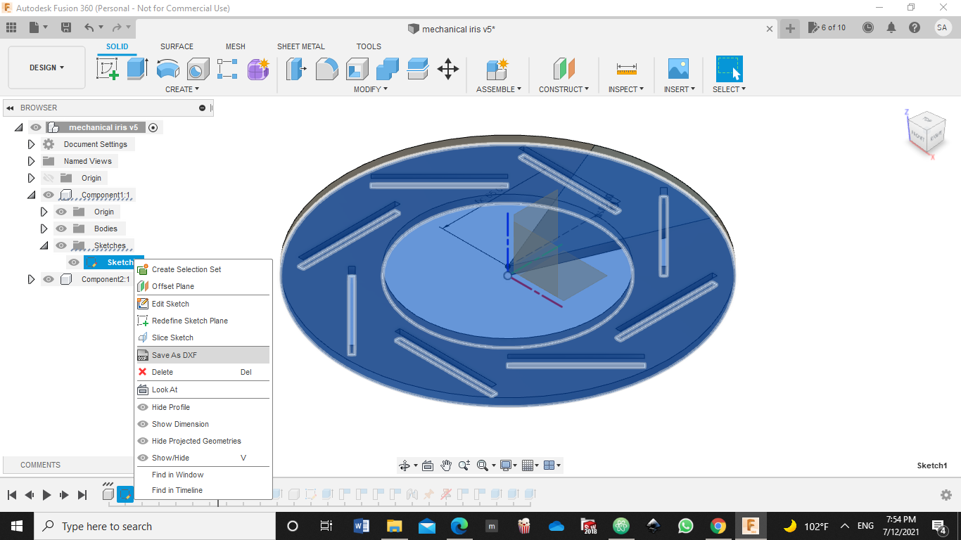
  • After Designing all the parts, and setting all the dimensions according to the sheet limitations, the design is ready to be milled.
  • First, each part should be saved in dxf format as the following, right click on the sketch of the part and save it as dxf file.


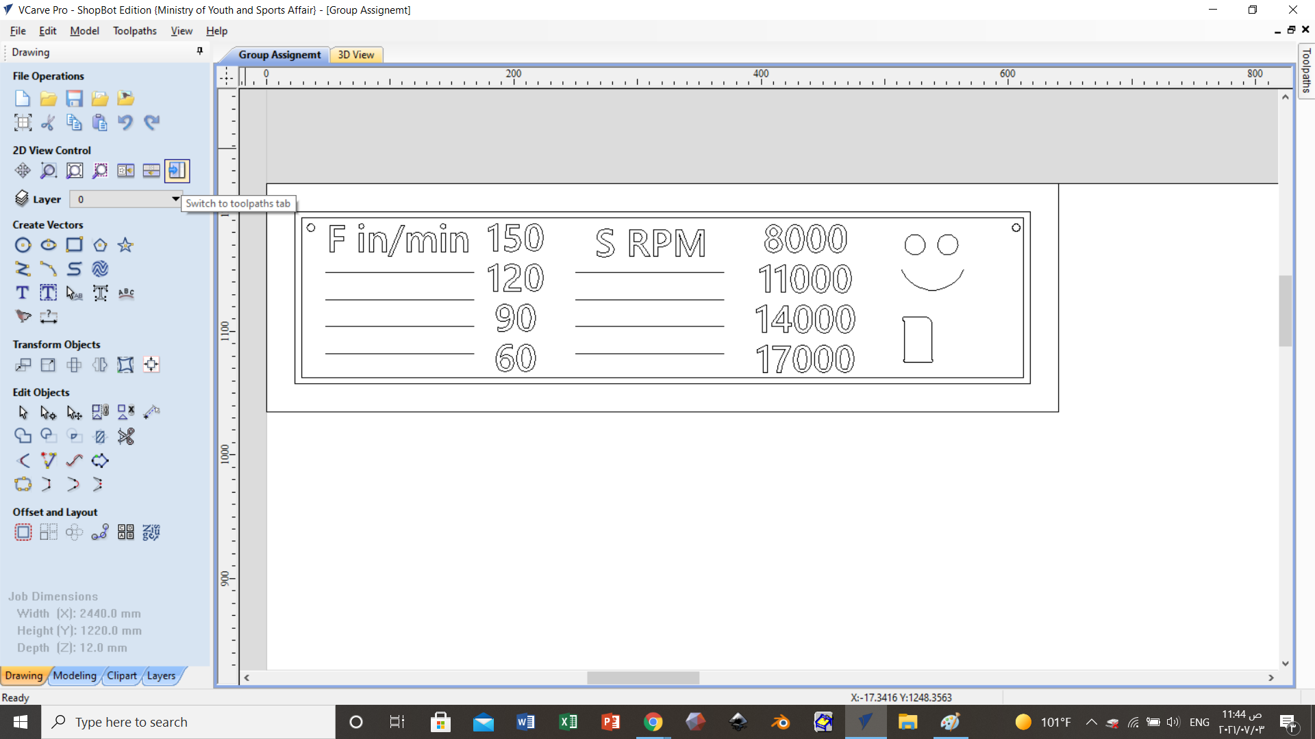
  • Afterthat, upload all the dxf files to VCarve, by first drawing a big rectangle having with dimensions of the sheet which are 2394x1174 mm. Then fit all the parts in this rectangle as the following.


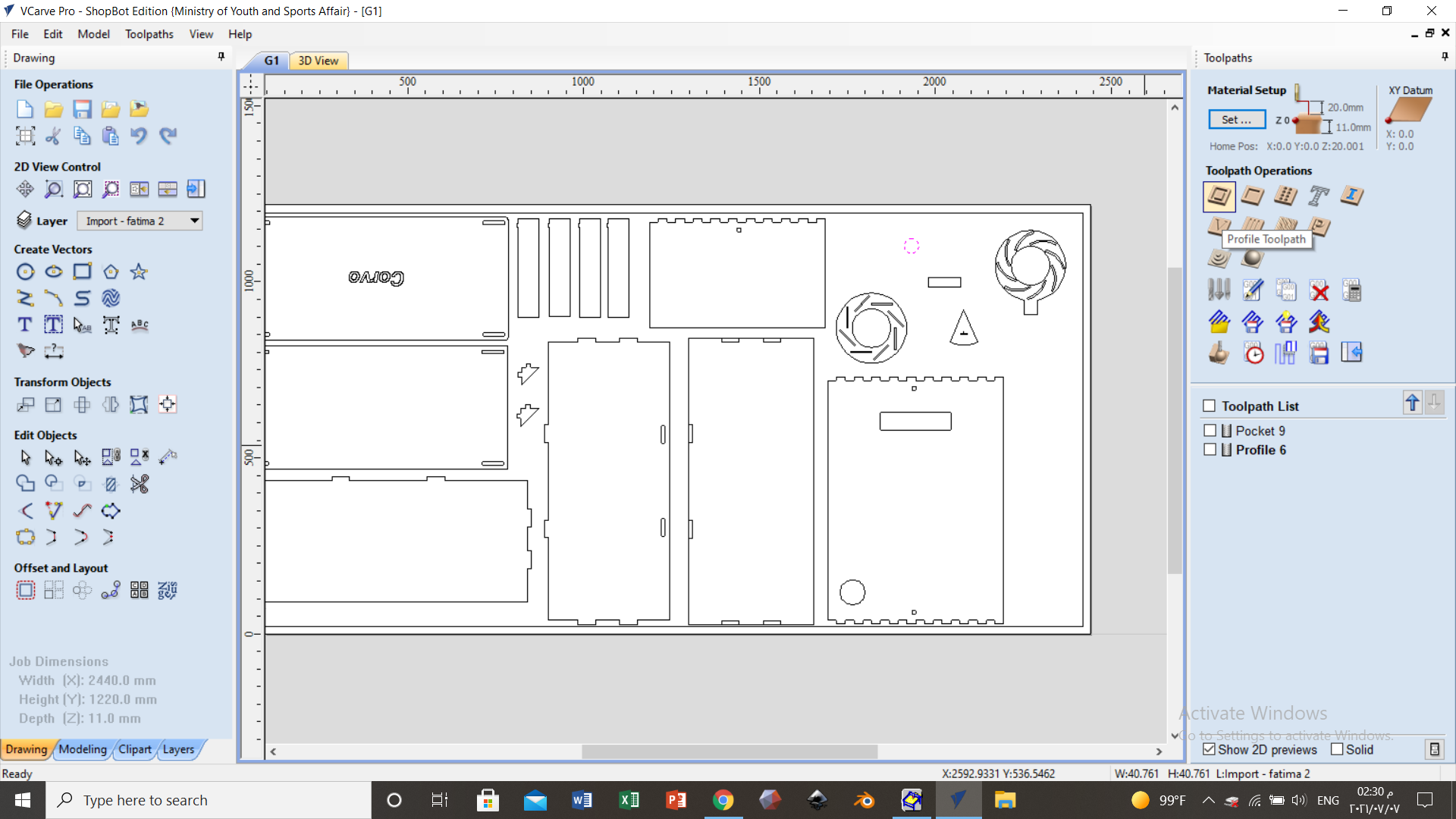
  • *Note that, here my design is too small comparing to the sheet, so there where empty area for other students to fit there design so that the machine will operate once. I also did one piece of the tringle instead of 8, and this is to test this part and how it will be fixed.
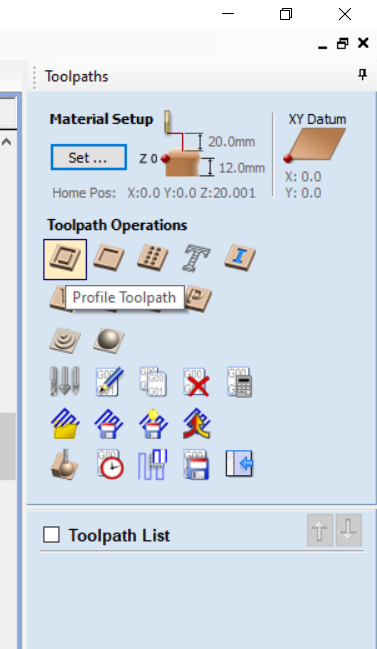
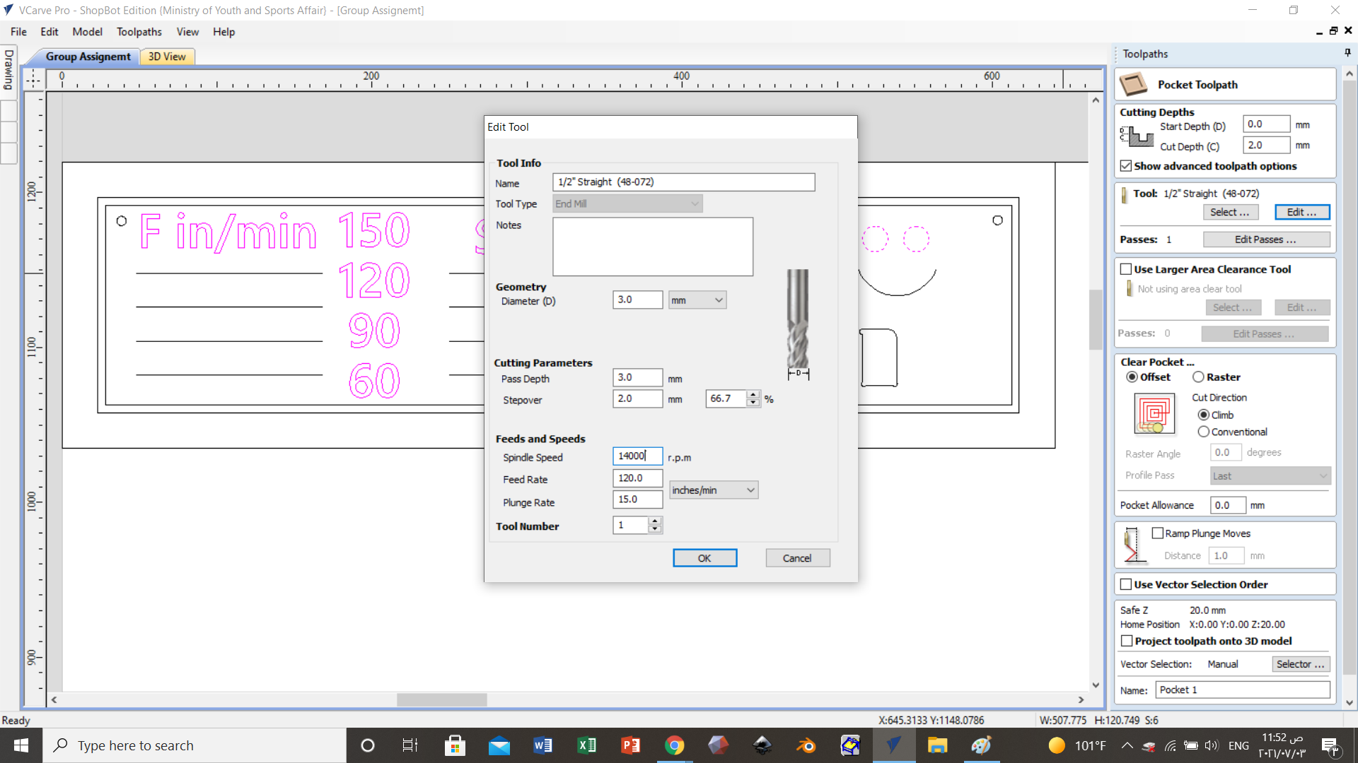
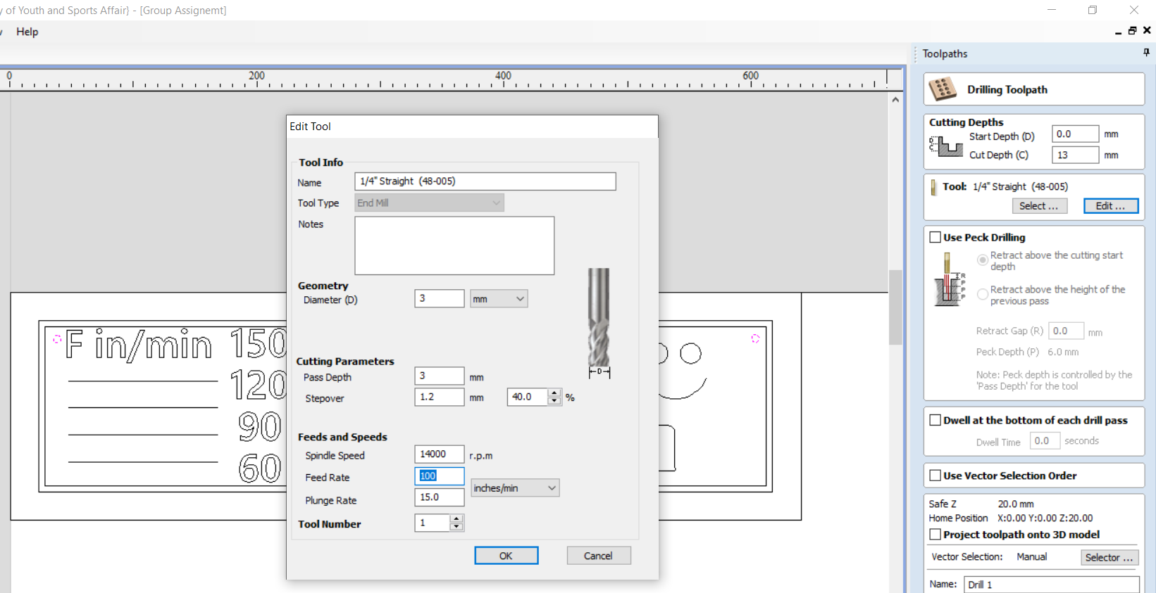
  • Now it is time to set the suitable toolpaths, for my desing I will just need a 2D Profile Toolpath to cut throught the sheet and there is nothing to engrave.


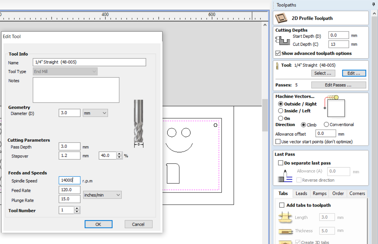
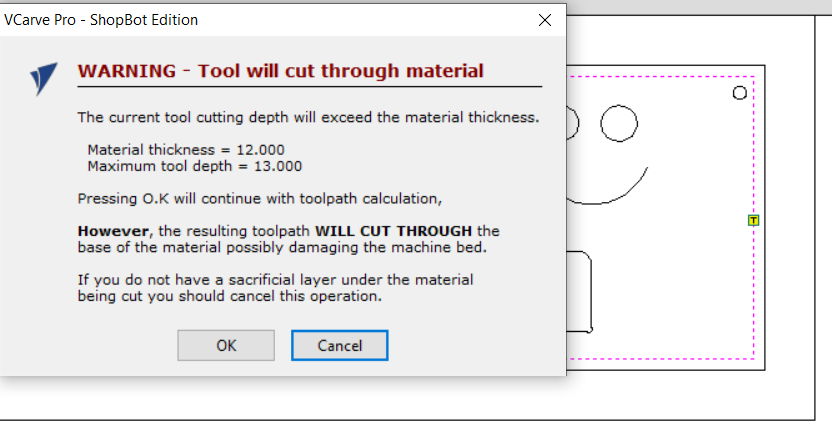
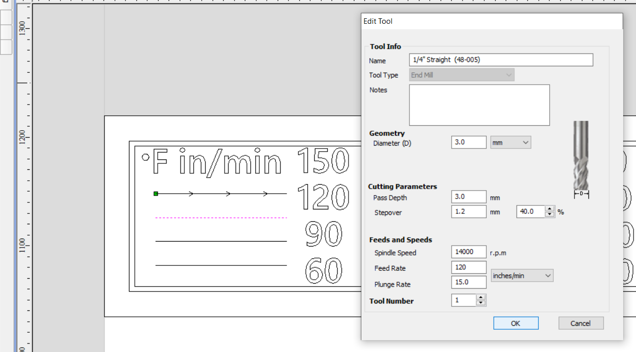
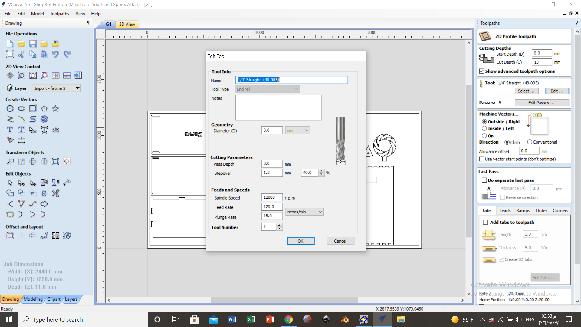
  • As you can see here, the tool is sat to cut at a depth of 13 mm with a spindle speed of 12000 rpm and a feed rate of 120 inches/min.


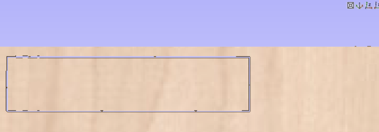
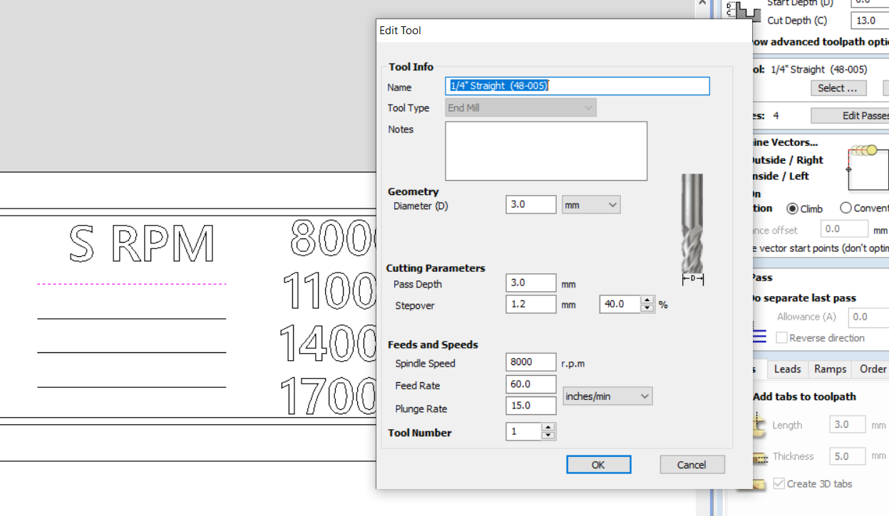
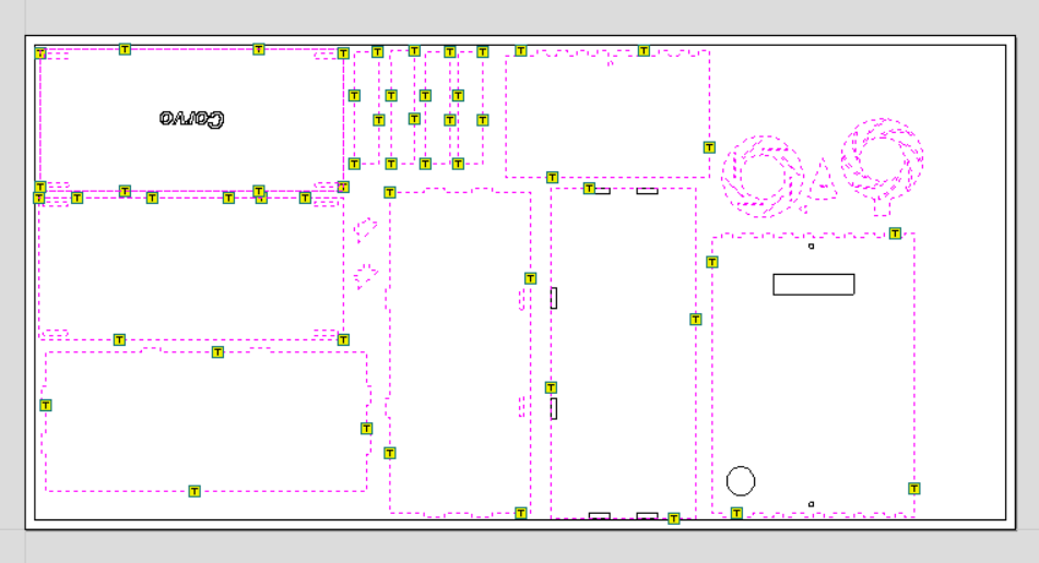
  • The dashed lines here are all sat to be cut through using the previously discussed settings.


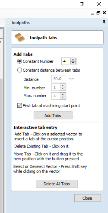
  • This option enables you to put tabs to hold the part fixed in its place after milling. From the settings here, the first tab will be added at the machine starting point, and after each 50 mm a tab will be added.


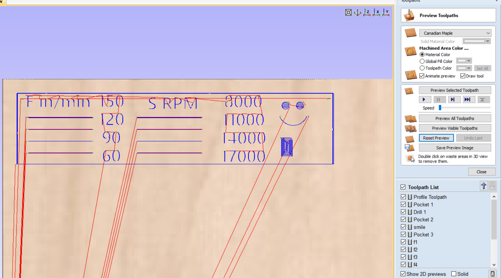
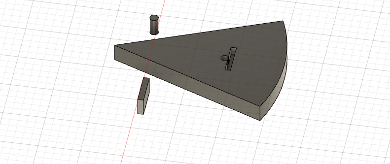
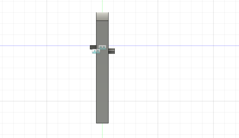
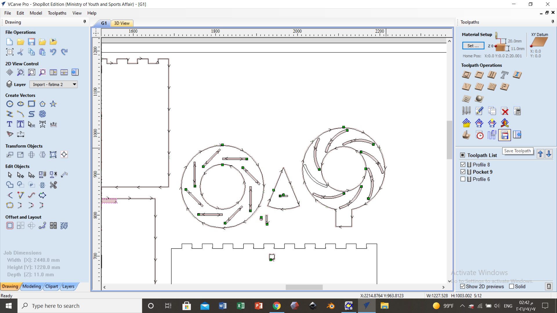
  • As you can see here, while taking a screenshot of my work to document, I un-choosed one curve but I noticed that when the milling process finished.
  • Also yo will notice from this figure that the pin and rectangular extude are too small, so they might no be machined.


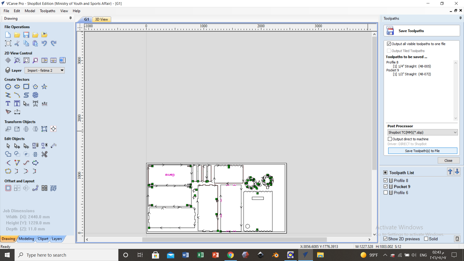
  • Afterthat, we saved to toolpath and you can see in the figure the toolpath list.


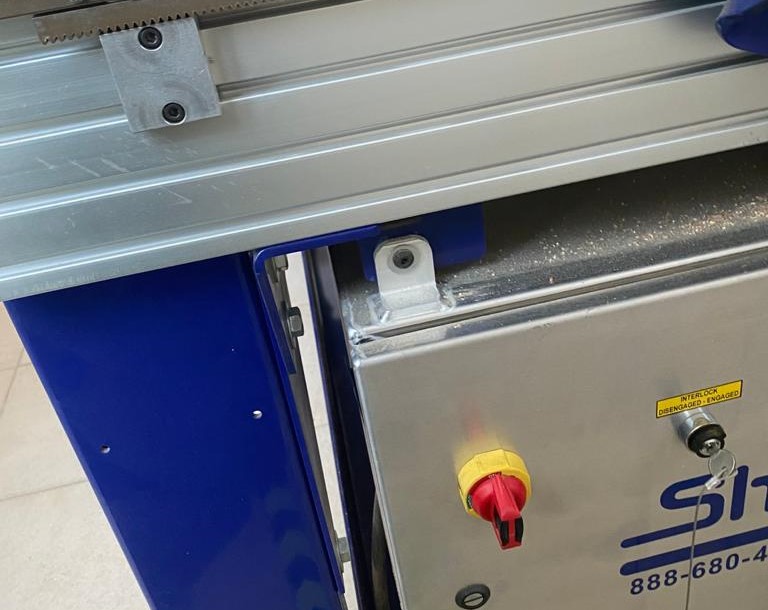
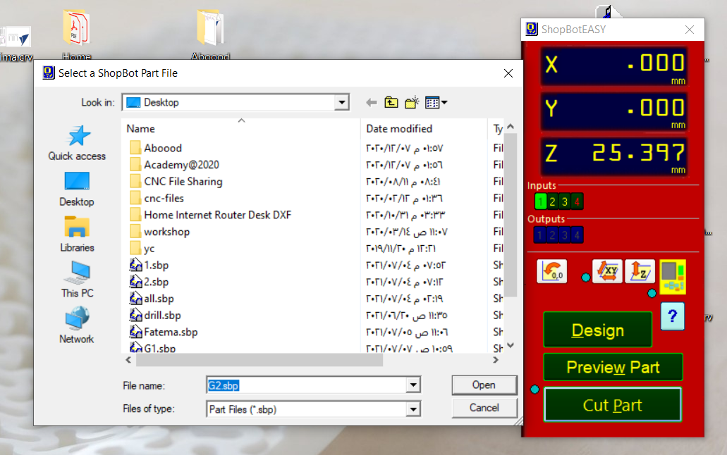
  • Now, upload the final toolpath from this machine frame appearing in the desktop.


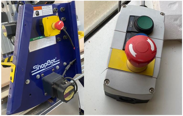
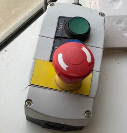
  • Press on the green button for 3 seconds for the spindle to start rotating.
  • *Make sure to wear the protective googles and keep away from any moving part in the machine.


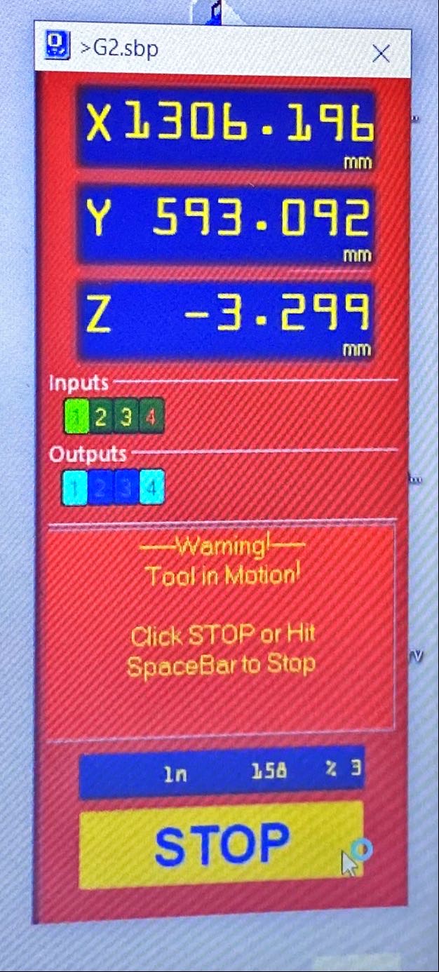
  • You can see here the coordinates of the tool in x,y,z directions an the progress precentage which is 3% here.


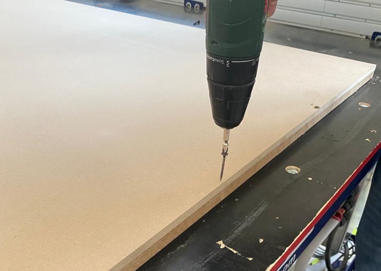
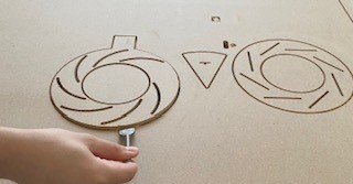
  • After finishing the milling process I used this tool to remove parts from the sheet. Once I applied force on the tool I hear a cracking sound, which is the breaking sound of the tabs.

  • *Notice here, that there is one curve missing so I will re-machine this part. From the figure, it seems that the pin and rectangular extrude are not perfectly machined, so I will think of something else to insert in the hole and slot instead.


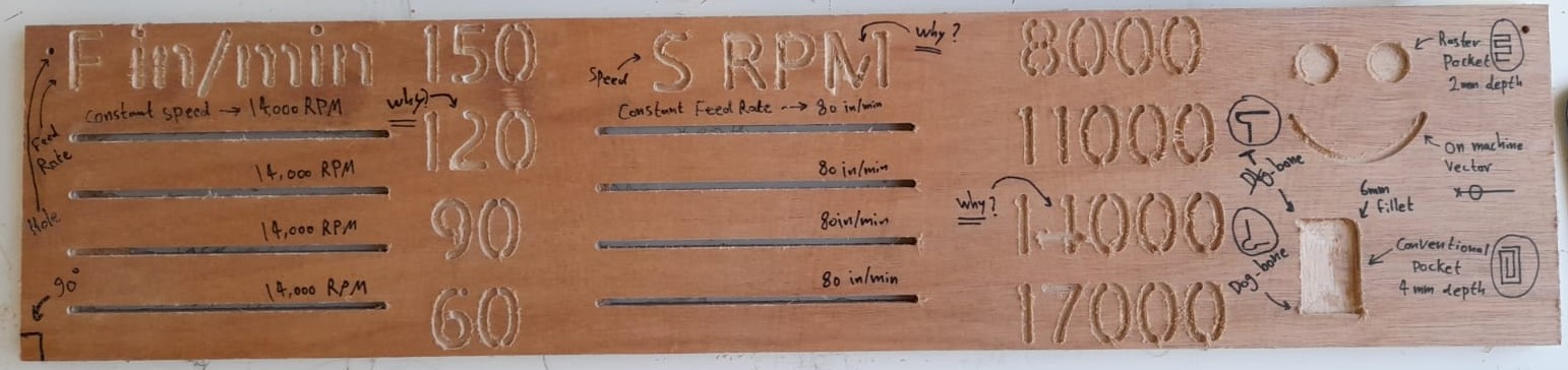
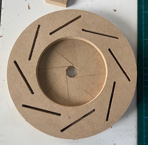
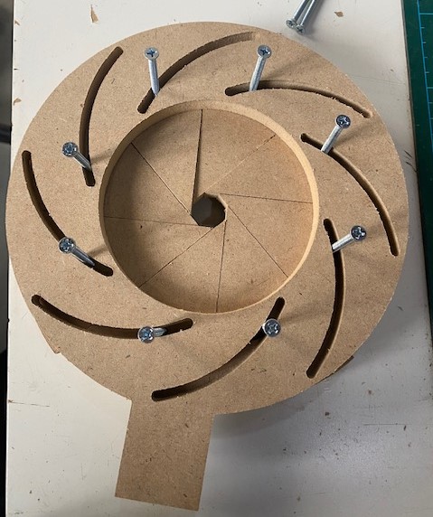
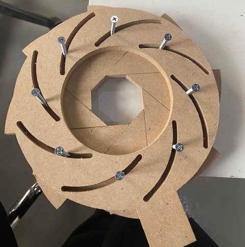
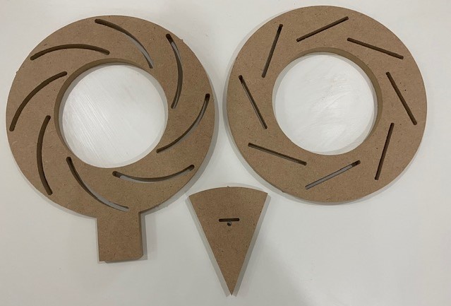
  • This is how the parts looked when I re-machined the ring that has a missing curve.


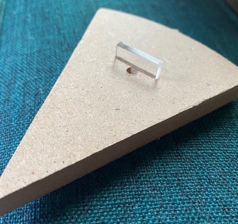
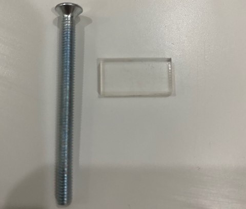
  • I designed a simple acrylic part with a dimensions of 19.4x10x3 mm using the laser cutter to be fixed in the slot for testing.
  • For the pin that should be fixed in the hole, I searched for screws in the lab that can fit in the hole.
  • After I checked that the acrylic part and screw are fitting, I machined the rest tringles.
  • Assembling the Mechanical Iris

  • After having all the parts machined, it means that we are ready to assemble the mechanical iris.
  • First, I fixed the acrylic part on each tringle.


  • Then, I placed the 8 tringles on the first ring (part #1), and the second ring (part #2) on the top.


  • Afterthat, I placed the screws throught the curves in (part #2) and fixed them on the holes of the tringle (part #3).


  • Finally, I applied force to on the handle to move it and open the mechanical iris as the following.


  • *As you can see, I could not fully open the mechanical iris because of the high friction. It was really hard to open and move.