
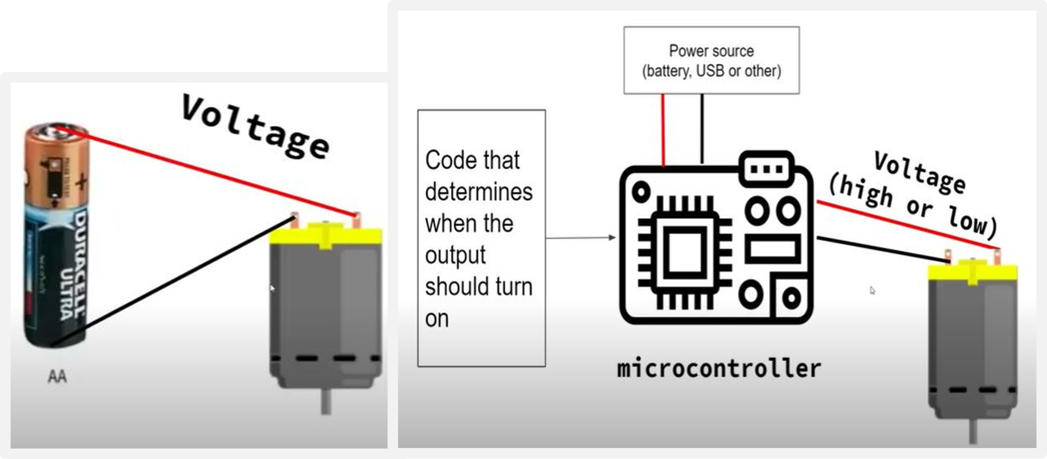
How to use the Breadboard
An important item in the kit is the Breadboard, Which is a rectangular plastic board having multi tiny holes to insert
different electronic devices such as LED, Servo Motor and Sensors,to build an electronic circuit.
To understand Breadboard better, and how the holes are connected I watched this video.
Breadboard will make the process of connecting devices to the Arduino Nano much easier, espacially when connecting more than one device to one pin.
To understand Breadboard better, and how the holes are connected I watched this video.
Breadboard will make the process of connecting devices to the Arduino Nano much easier, espacially when connecting more than one device to one pin.
Introduction to Input Devices
b. Piezo Buzzer
Servo Motor Built-in Example
The first device I will be using from the kit is the Servo Motor, which is an output device.
Where I will write a code using Arduino IDE, upload it to the Arduino Nano, and then the Servo Motor will operate.
To begin, I used a built-in example called Sweep. The servo motor has Three wires to be connected:
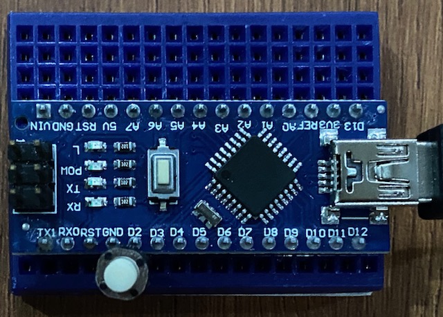
1. Ground wire(brown or black) to be connected to GNF on the Arduino Nano.
2. Power wire (red) to be connected to 5V on the ArduinoNano.
3. Signle wire (yellow) to be connected to a digital pin on the Arduino Nano.
*You can see below how to connect wires between the Servo Motor and Arduino Nano.
*Press on Code to see the written code, and then on Start Simulation to see how the code is working.
To begin, I used a built-in example called Sweep. The servo motor has Three wires to be connected:
1. Ground wire(brown or black) to be connected to GNF on the Arduino Nano.
2. Power wire (red) to be connected to 5V on the ArduinoNano.
3. Signle wire (yellow) to be connected to a digital pin on the Arduino Nano.
*You can see below how to connect wires between the Servo Motor and Arduino Nano.
*Press on Code to see the written code, and then on Start Simulation to see how the code is working.
Building a New Servo Motor Code
To build a new Servo Motor code, I wanted to write a code that will rotate the Servo Motor in a 360 continuous rotation.
And here I tried my best but couldn't do it, after searching I realized that the Servo Motor I have is able to rotate only
to 180 degrees and it is called Stanard Ervo Motor, while there is another type that is able to rotate in 360 degrees
called Cotinuous Servo Motor.
So, I wrote this code below that contains short sentences explaining each step. *This code will rotate the shaft from its initial position to 90 degrees, wait for 1 second, then rotate from 90 degree to 180 degree, wait for 1 second, then rotate back to its initial position. After that, it will have a continuous rotation from 0 degree to 180 degree, and this is by adding 1 degree step each time using a for loop, with adelay time between steps of 15 milliseconds which is fast. Finally, the shaft will return back from 180 degree to 0 degree by subtracting 1 step, with a delay time of 30 millisecond between steps wchi is slower that the step before.
*To see how the code is working, I upload is to TinkerCad by changing the code language from block to text, then I pasted the codes, and finally press on start simulation to see how the motor's movement changes.
*And Then I uploaded the code to my Arduino to see the result on the Servo Motor I am having.
Piezo Buzzer Built-In Example
The second output device I am having in the kit is the Piezo Buzzer,
a device that generate basic beeps and tones using a piezo crystal. A piezo crystal is a material that changes shape when voltage is applied it. By changing the
frequency of the voltage, the piezo will start generating sounds by changing shape very quickly.
To start with the Piezo Buzzer I used the built-in example called ToneMelody and the code to do it is shown below. And here is how I connected the Piezo Buzzer to my Adruino showing the wiring connections to the pins.
To start with the Piezo Buzzer I used the built-in example called ToneMelody and the code to do it is shown below. And here is how I connected the Piezo Buzzer to my Adruino showing the wiring connections to the pins.
Building a New Piezo Buzzer Code
To practice more and write a code to operate the Piezo buzzer, I wanted to write a code that will
play the Birthday song.
I used a table shared by my instructor Duaa AlAali that contains frequancies and durations required to build the whole song. Refrencing to this table, I was able to write a code that will plays the birthday music.
And here is a video showing the result.
Refrencing to this table, I was able to write a code that will plays the birthday music.
And here is a video showing the result.
I used a table shared by my instructor Duaa AlAali that contains frequancies and durations required to build the whole song.
Refrencing to this table, I was able to write a code that will plays the birthday music.
And here is a video showing the result.DigitalInputPullup Built-In Example
I used DigitalInputPullup example to understand how the Push Button provided in the kit used.
This example will blink the built-in LED light if it is pressed, read a digital input and prints the results to the Serial Monitor. This digital input will be taken from the Push Button if it is pressed or not.
So, I connected the Push Button to the Arduino Nano using two jumpers, one is connected to pin GND, while the other one is connected to pin D2 as shown below.
After uploading the code, I opened the serial monitor to see the result. By selecting Tools/Serial Monitor.
Building a New Push Button Code
To Practice the Push Button more I built a new code that links the Push Button to the movement of Servo Motor.
Where I connected the Push Button as before to Pin D2 and Pin GND, while the motor to Pin GND, Pin 5V and Pin D9.
As a result of this code, the motor will rotate to 180 degrees if I press the Push Button, and return to 0 degrees if it is un pressed.
As a result of this code, the motor will rotate to 180 degrees if I press the Push Button, and return to 0 degrees if it is un pressed.
AnalogReadSerial Built-In Example
The second input device I am having in the kit is MH-Sensor-Series looking as:
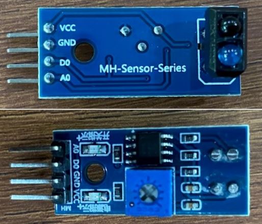
As shown in the figure the Sensor has four main pins, VCC to be connected to 5V, GND to be connected to grounf, D0 to be connected to a digital pin,
and finally A0 to be connected to analog bin.
I used the AnalogReadSerial example to read analog input and print the result on the Serial Monitor.
After uploading the code, I opened Serial Monitor window to see the results and it seems that if I put a white item infront of the Sensor a low number will be displayed on the Serial Monitor,
while black items will result in high number.