week5
Computer-Controlled
Machining
What I did
-
This week
we were introduced to the CNC machine.
We did a group assignment to test the alignment, speeds, feeds, and toolpaths of the machine.
I worked on makinng (design+assemble) something big.

CNC Machining
In the Computer Numerical Control (CNC) machining process, production equipment and tools are moved according to pre-programmed computer software. The procedure may be used to operate a variety of complicated machinery, including mills, CNC routers, lathes, and grinders. Three-dimensional cutting jobs may be completed with CNC machining in a single set of instructions.
When a CNC system is switched on, the intended cuts are programmed into the software and sent to the appropriate tools and machines, which do the prescribed dimensional jobs in a manner similar to a robot.
CNC Machine Programming
Numerical control, which designates a software program to control an object, is used to operate machines in CNC production. G-code, another name for the programming language used in CNC machining, is used to specify how a particular machine should behave in terms of its speed, feed rate, and synchronization.
In essence, CNC machining enables machine tool tasks to be pre-programmed for speed and location, and to be executed by software in predictable, repeating cycles, all with little input from human operators. A 2D or 3D CAD drawing is created for the CNC machining process, which is then converted into computer code for the CNC system to execute. The operator runs the software once it has been inputted to make sure there are no coding errors.
How CNC Works
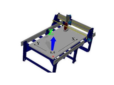
With the use of CNC tools, a cutter may move in three dimensions and cut a variety of designs by being moved around a large table on the X, Y, and Z axes. The cutter, which resembles a drill bit, is rotated by a motor known as a router or spindle. A router bit, in contrast to a drill bit, is made to cut both from the sides and the tip. A ShopBot CNC tool can cut practically any design or shape out of materials including wood, plastic, foam, metal, and various composites by carefully sliding the cutter through the material.
Main parts

2D and 3D types of design


A 2D design is essentially a flat, 2D plan of the project. CAM functions can be used to have some areas of the plan cut or pocketed at different depths. This type of work is sometimes considered 2.5D because there are movements in and out of the material. V-carving is a great way to add a more dramatic look to your lettering or sign work and decorative wood carvings. In full 3D machining, your CNC cutter tip follows angled paths or 3D curves in order to mill or carve complex shapes. Designing in 3D is harder than 2D, but takes full advantage of your CNC tool's capability to produce fully contoured shapes. You will create the 3D shape of your concept in a 3D design system, defining the form that you want to cut.
Types of cutting tools

There are many types of cutting tools, but the 3 major ones are:
UPCUT: Bits that upcut chips and the substance pull them upward. Your material must be strongly held down when using them. If you wish to remove chips from your cuts to stop the bits from overheating, upcut bits are preferred. They work really well at slicing through the material. The most typical cut is an upcut.
DOWNCUT: Using downcutting bits forces the material and chips back into the cut. The top surface of your material will be well-preserved by their downward shear action. The bottom layer of the workpiece will be pushed away from the bit by chips, making these bits less effective for drilling holes but better for cutting thin, flexible materials. Although they may tear the bottom edge, downcut bits leave a clean cut at the top of the workpiece.
COMPRESSION CUT: Compression bits, often known as up-down bits, combine the advantages of upcut and downcut bits. Even though the bit is a typical downcut, its tip is an upcutter. Because the top is pushed down while the bottom is lifted up, while cutting materials like plywood, you will get a clean edge on both sides. By combining the two geometries, chipping is avoided, and there is a lower chance of workpiece damage.
Safety
The machine operator, as well as any spectators or observers, must wear eye and ear protection. Flying debris, such as material chips and sawdust, can seriously harm eyes.
Always put on closed-toed shoes.
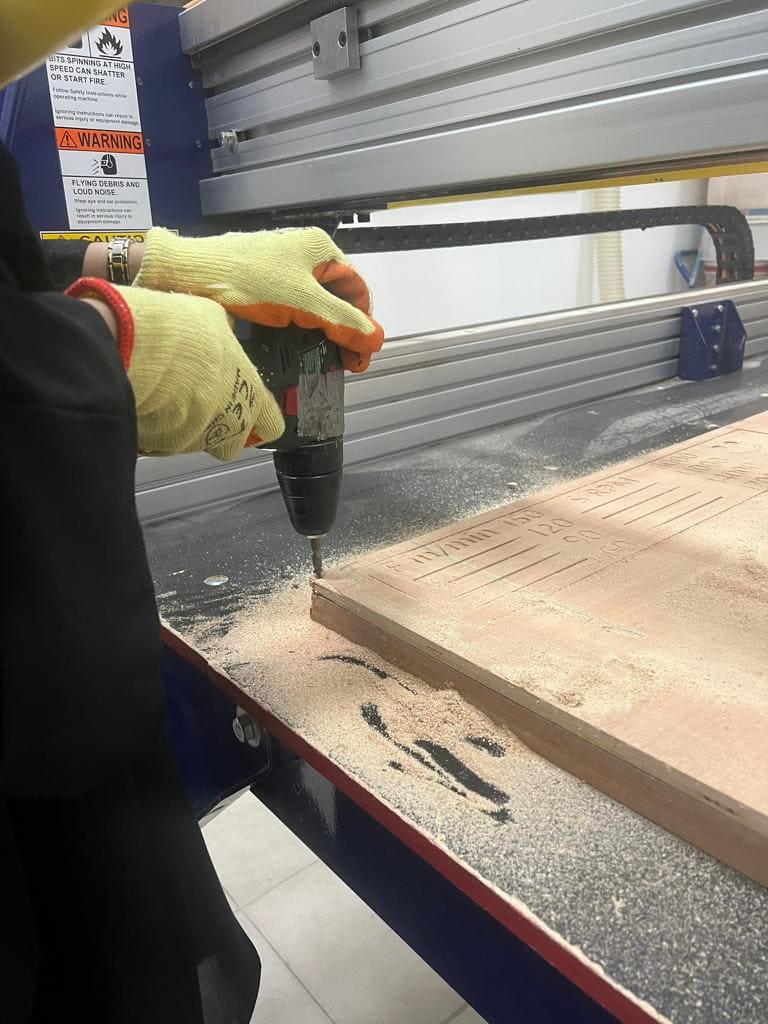
Before cutting, make sure your material is securely fastened on 4 sides.To fasten your shet on top of the sacrificial sheet, use a hammer and some screws or a power drill and some screws.
A gap between the sheets should not exist.
A running computer should never be left alone. Recognize that a spinning tool creates a fire risk because it produces heat and friction. By utilizing the proper chip load, sharp bits, and consistently verifying your files twice before cutting, this danger is reduced. If something appears off or dangerous, be ready to pause or stop the cut.
There are 3 ways "which I know" to stop the machine from working, the first one is when you hit spacebar in the keyboard, this words if you want to pause the cutting without having to repeat the settings and the work you did, another way is by hitting the red stop button or the switch,This will stop all systems' electricity. The locations will no longer be precise, thus you will need to re-zero all of your axes before moving ahead.


Group Assignment
For group assignment you can visit my colleuge
Sara's page
Indivisual Assignment
Getting Started!
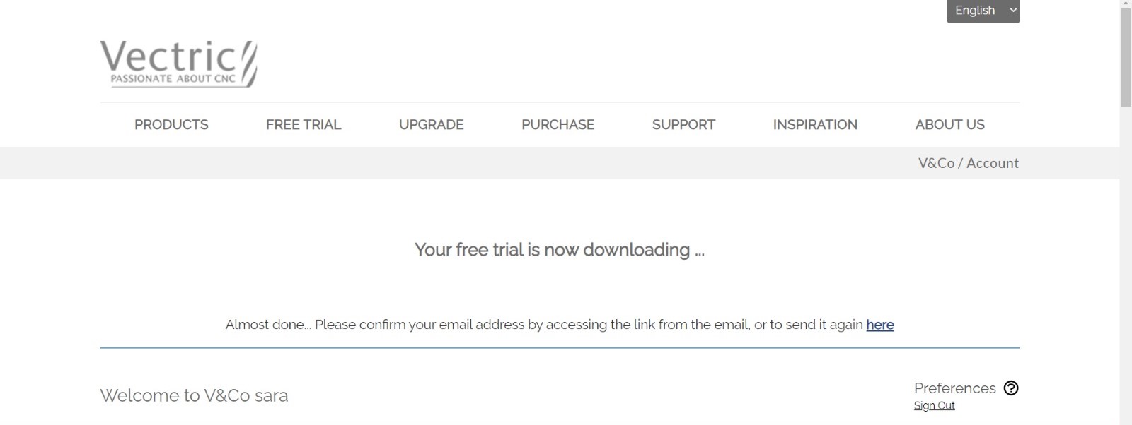
1.Downloading the necessary softwares
For CNC machine you will need the following softwares: 1.ShopBot3 2.ShopBot Editor 3.VCrave
In my case I only downloaded VCrave to edit my drawings, because the other softwares were already downloaded on the computer in the CNC room.

2.Design stage using Fusion360
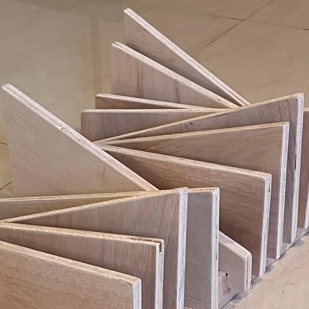
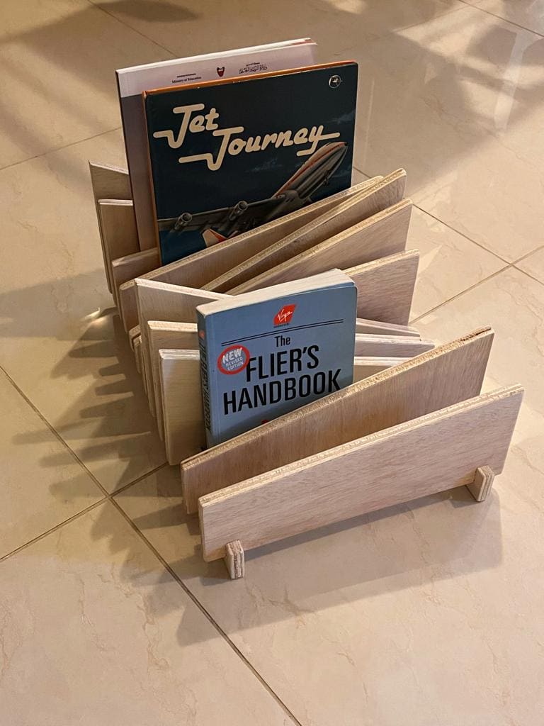
I wanted to make a book organizer because I have many new books and because I need a new art piece for my living room
I started my outlines in Fusion and I opened a new sketch, chose the required length and width of my object and made the same gap size for each triangle
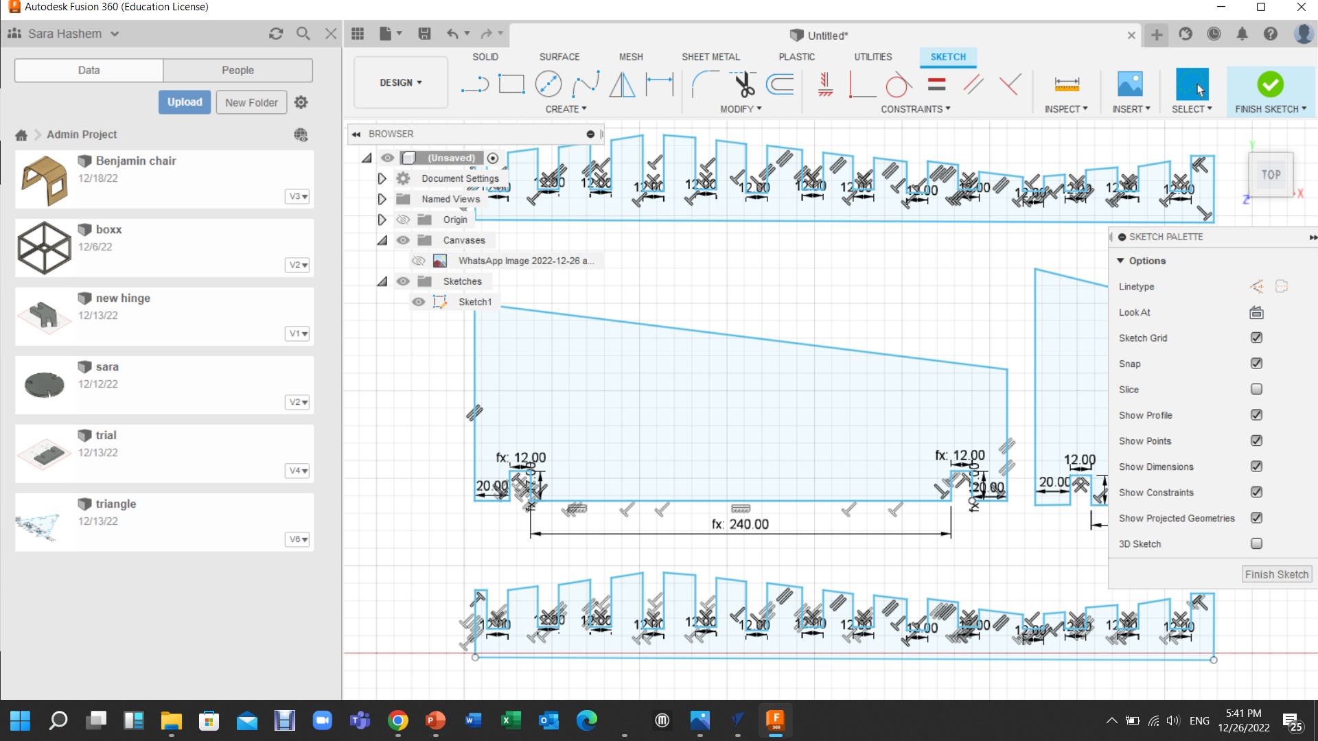
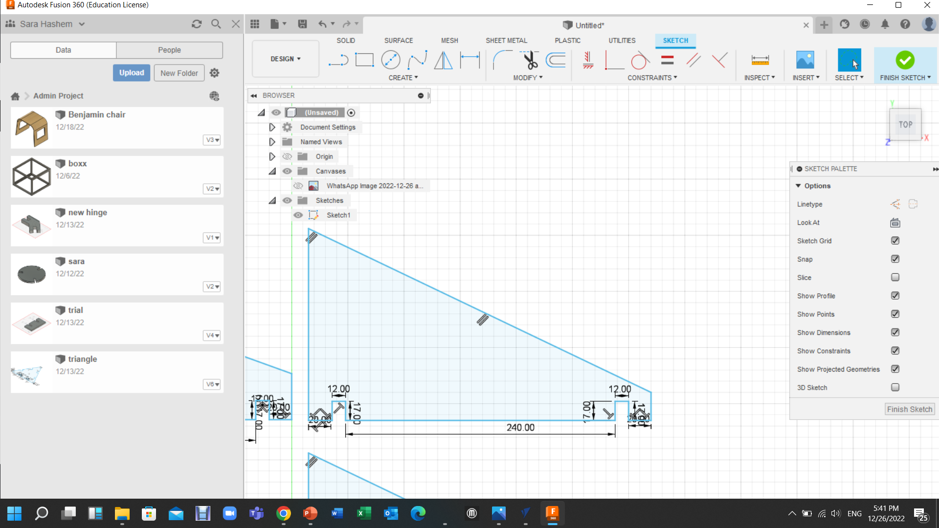

The goal was to create a wave-like surface by using several triangles with various angles, some of which are sharper than others.
To lock in my dimensions and make it simpler to update them in case of a mistake during assembly, I used the "change parameters" option.
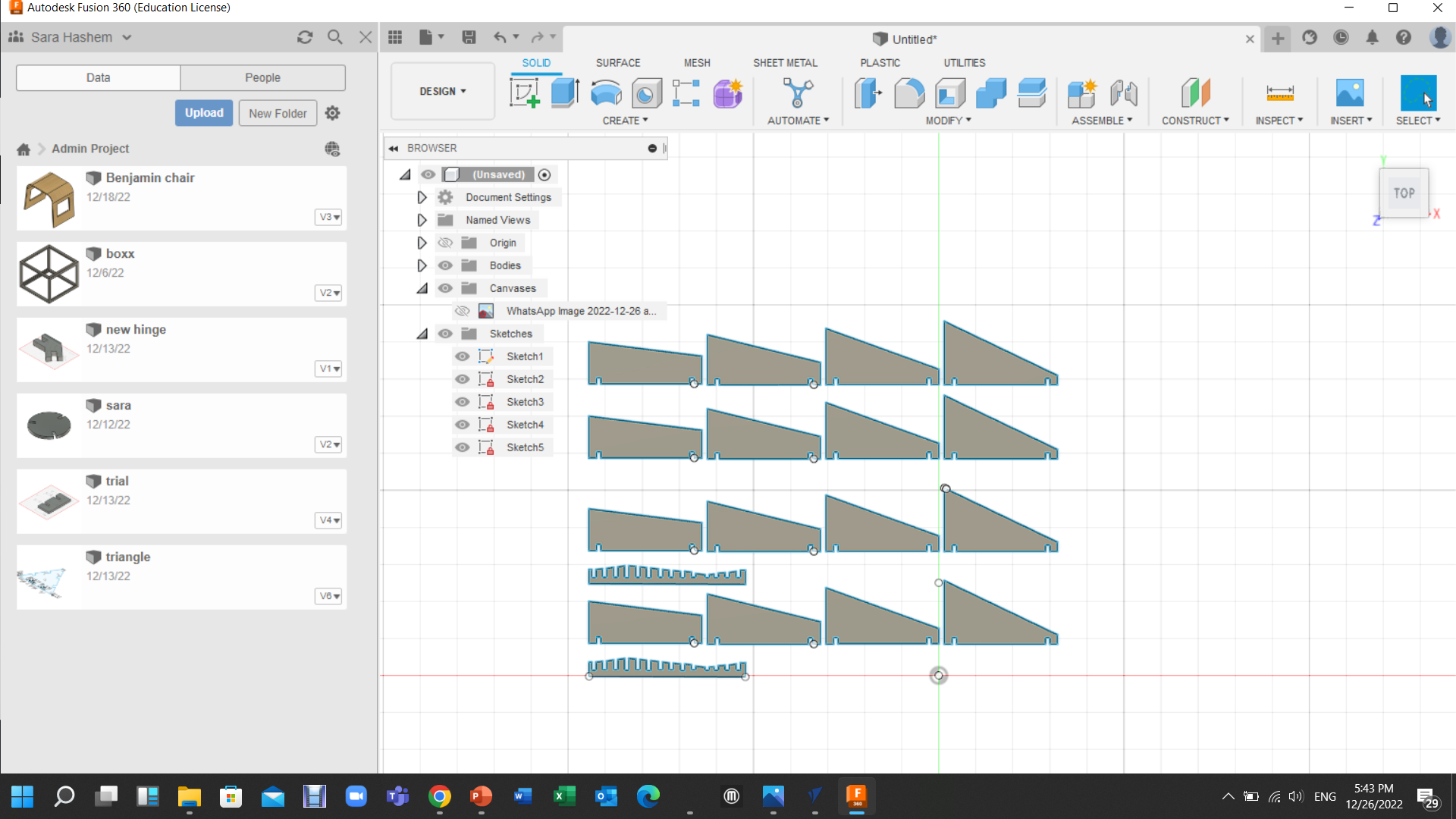
I made the openinga 12mm wide because the board I'm using has a 12mm thickness. I created a base for the triangles and dublicated it to have one on each side.
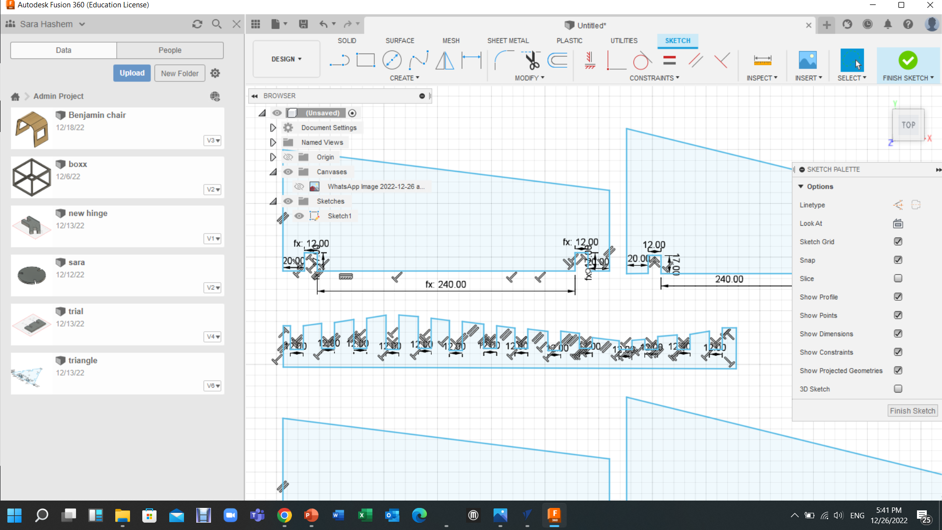
by extruding the pieces and dublicating them to have four of each triangle, I exported the sketch as a DXF file to be ready for the next step

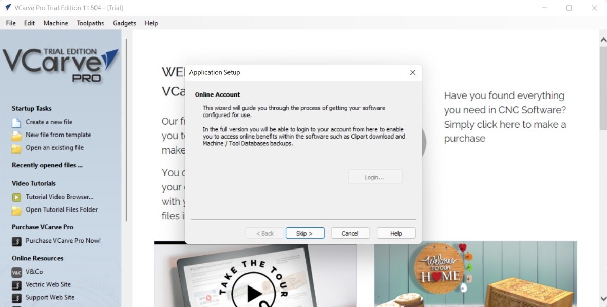
3. Editing the design in VCrave
Enter the sheet's measurements (Width, Height, and Thickness), choose "zero corner" as your starting point, and then click OK.

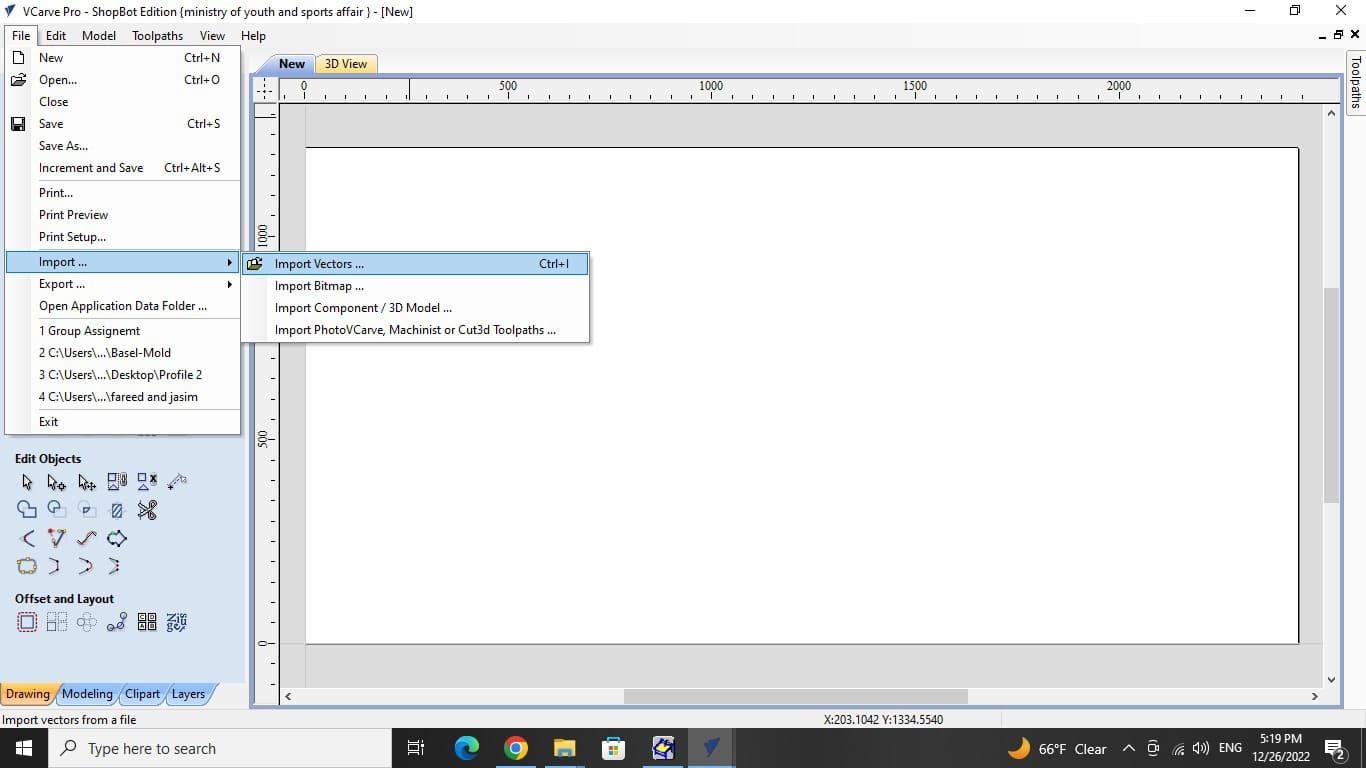
Press Ctrl + I to import your vector file, or go to file and click import.
Then take your object and move it away from the edges. use the arrow keys to move it or scale it and make it larger using the same tool.
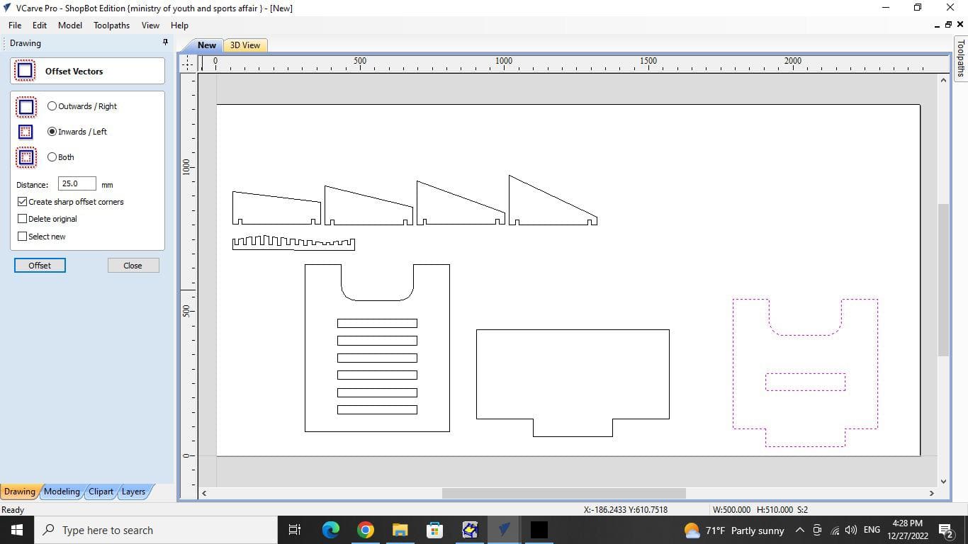
I drew a rectangle with a 25mm inward offset over the whole drawing area. To prevent the machine from touching the screws.
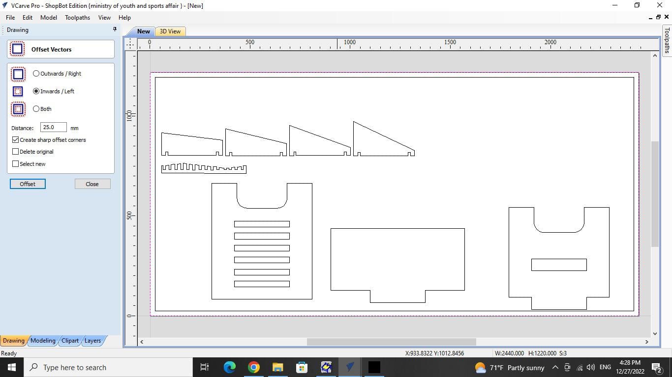
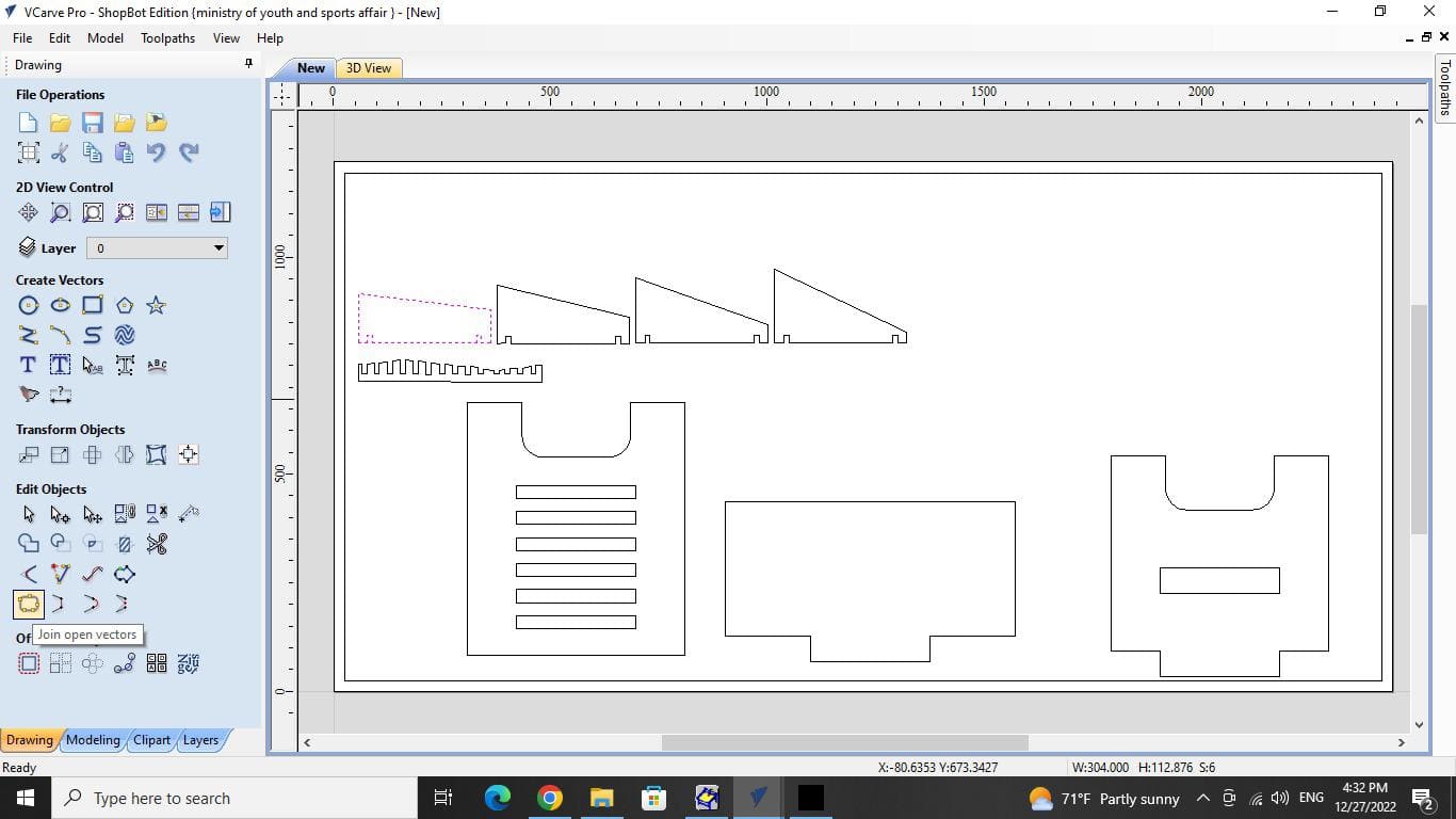
I selected each object alone and noticed that the lines were not connected. I used the join open vectors tool and the value 0.000 to close the gaps and create a single object.
Start adding fillet for the corners where two objects will meet, I chose T-bone fillet with a radius of 1.5mm

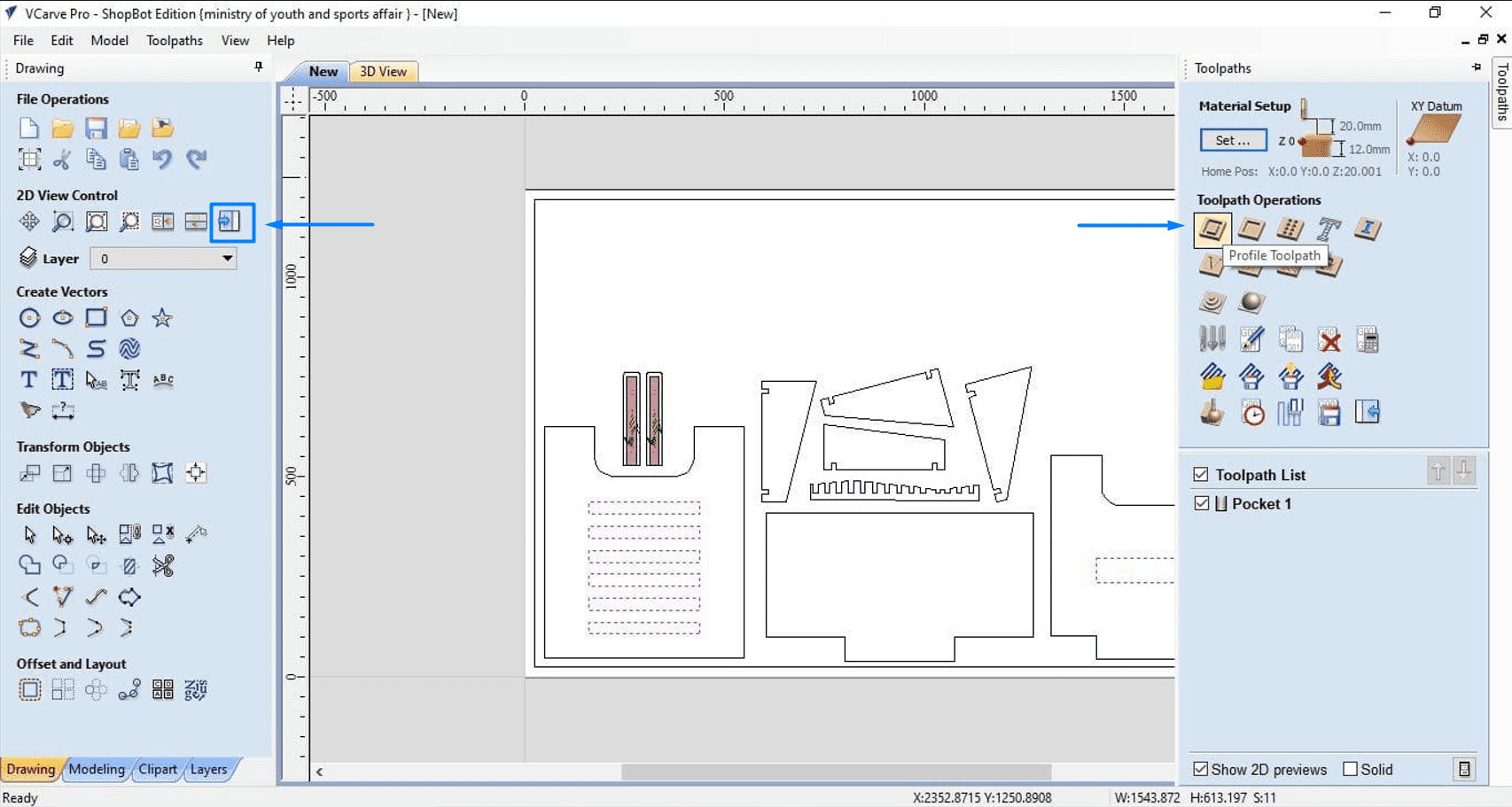
Change to the toolpaths tab
Click profile toolpath. With the use of this tool, we will perform a single, straight cut. Next, we will pick the cut-target vector; in this case, we will select the internal components first then repeat the following steps for the external lines as well. In case you want to ingrave only, select the object then hit pocket toolpath.
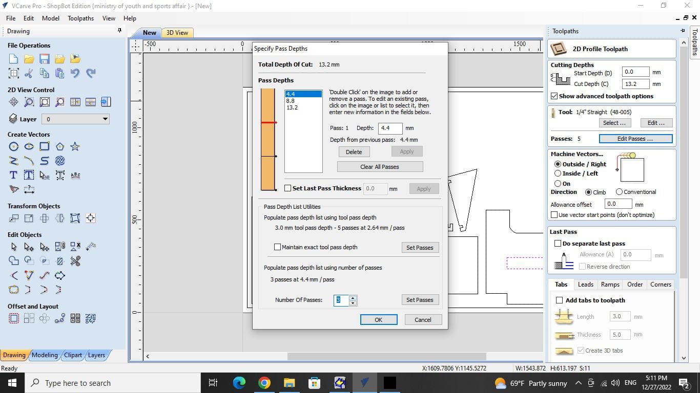
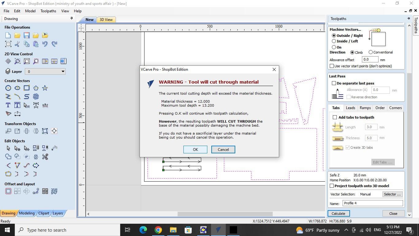
After that, adjust the cutting depth and note that I increased the material sheet's thickness by 1.2 mm. Note that I have already put a wood sacrificial sheet on which the additional 1 mm will be etched. This is to guarantee that the components are cut accurately.
Then, you must select the type of tool by clicking on Edit. Based on several trials we carried out during the group task , I altered the spindle speed and plunge rate.
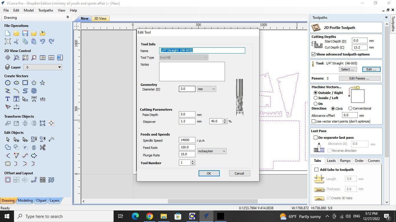
Then chose the number of passes, or how many times the machine will make a cut. In this case, I picked three to guarantee that the cut is complete. then hit OK
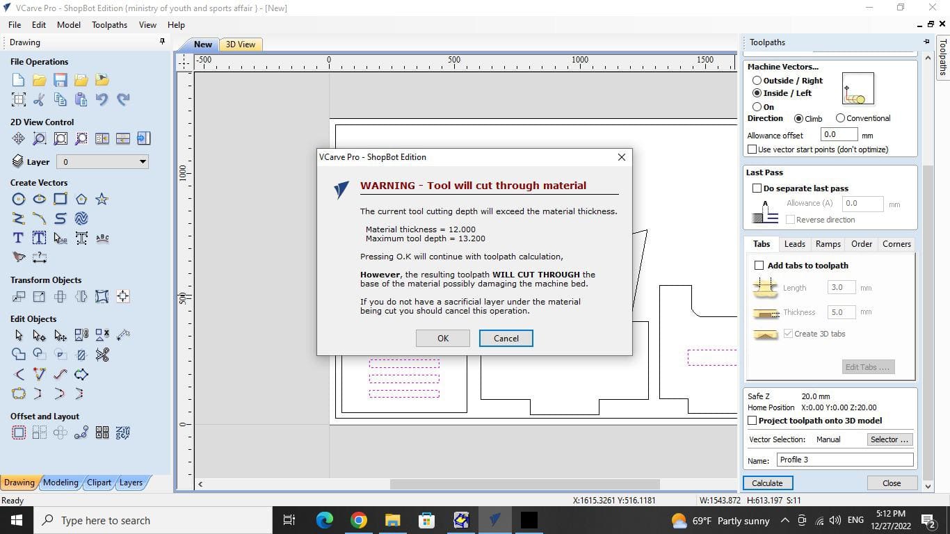
A warning will appear but you can ignore it because you have the sacrifice sheet underneath
Click preview toolpath and play button to display the cutting process and make sure it's correct.
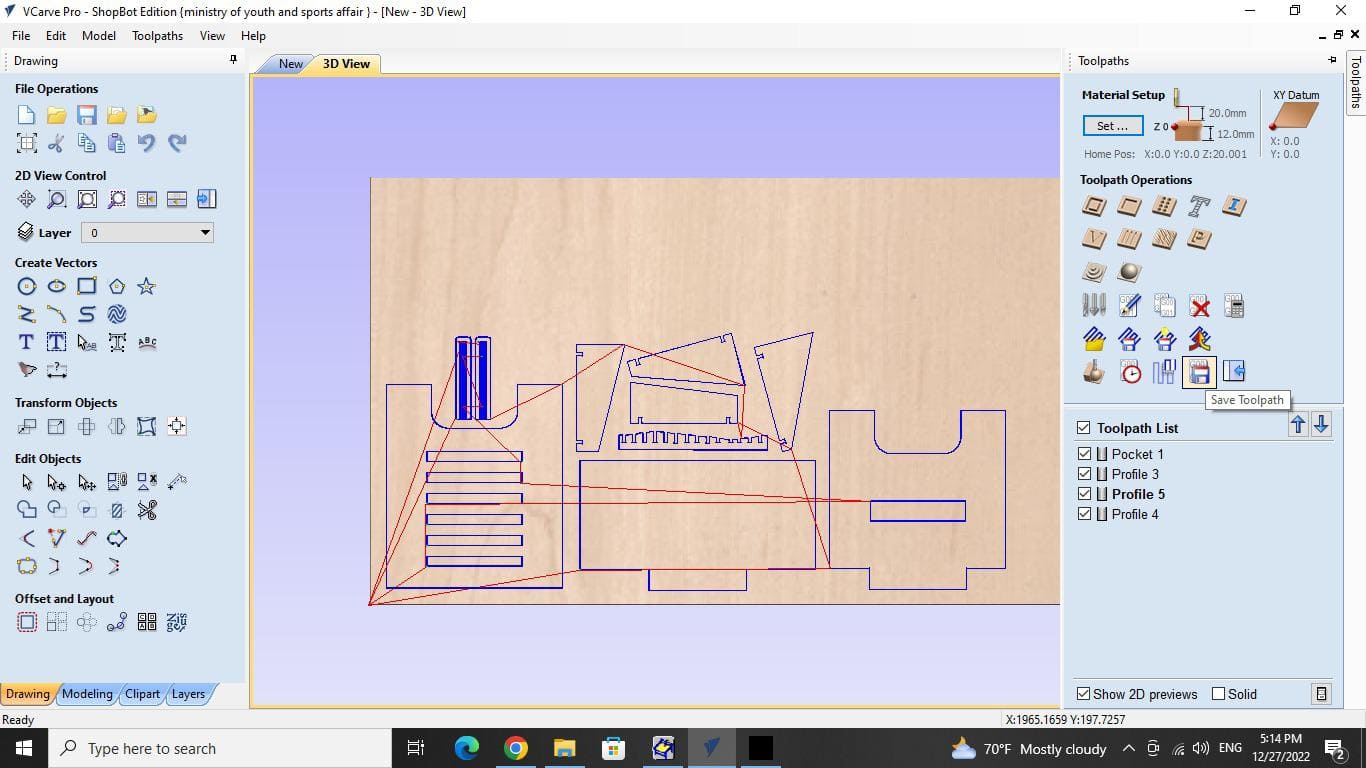
Click the save toolpath button after making sure all toolpaths are chosen.


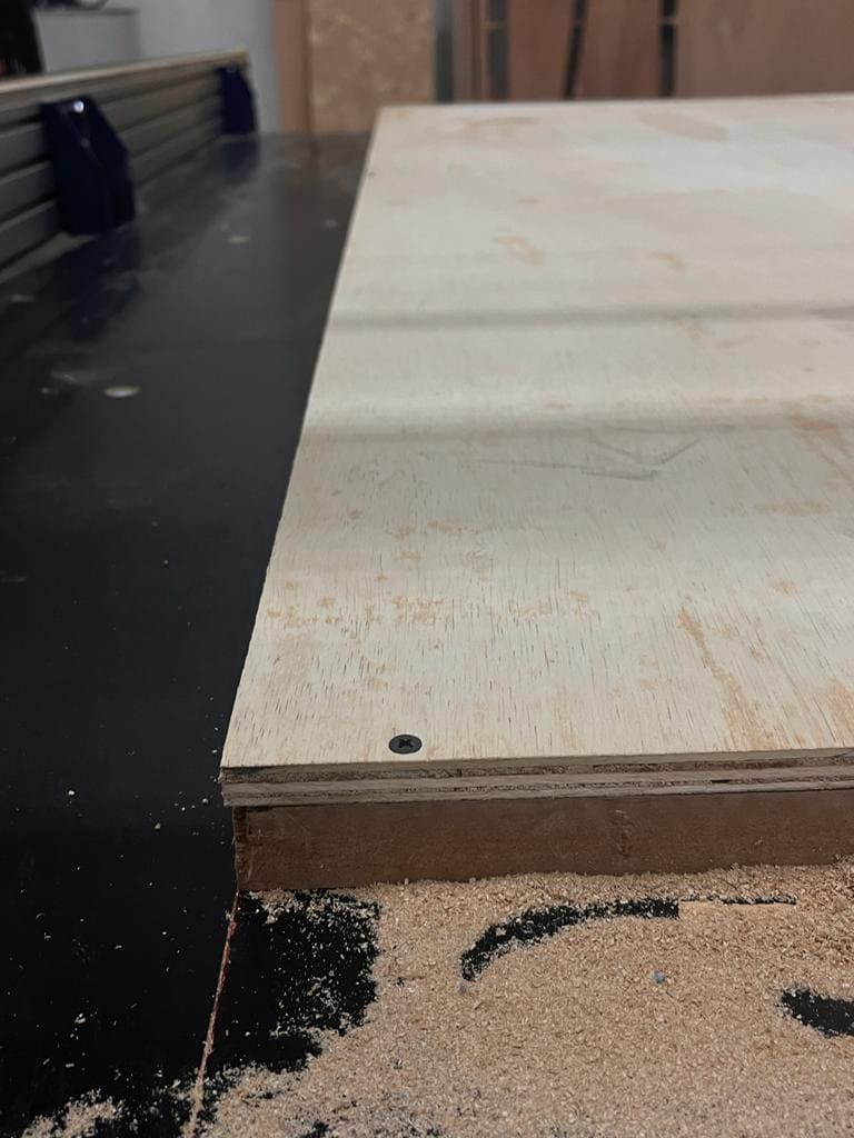
Placing the sheet
1. Place your sheet over the sacrafice sheet.
Use screws on all 4 sides and make sure there are no gaps.
Shopbot
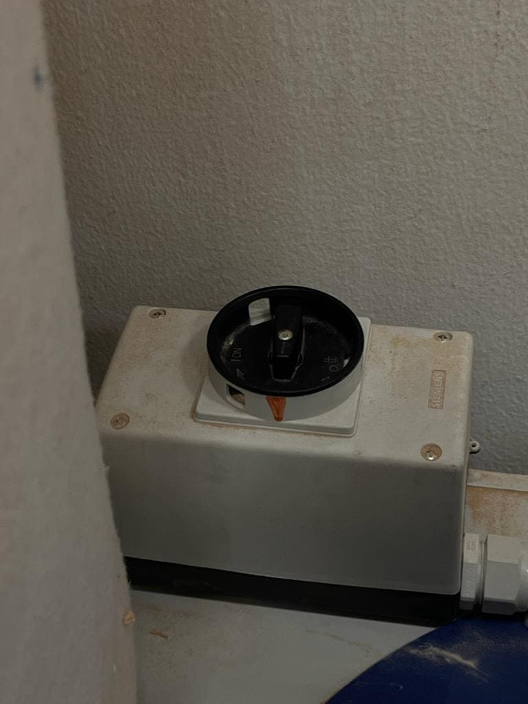
Launch the ShopBot 3 software. If a warning occurs saying "STOP, buttin is ON", click OK after pressing the blue reset button.
Clibration and setting the zero
1. Select "Keypad" the one with the yellow panel.
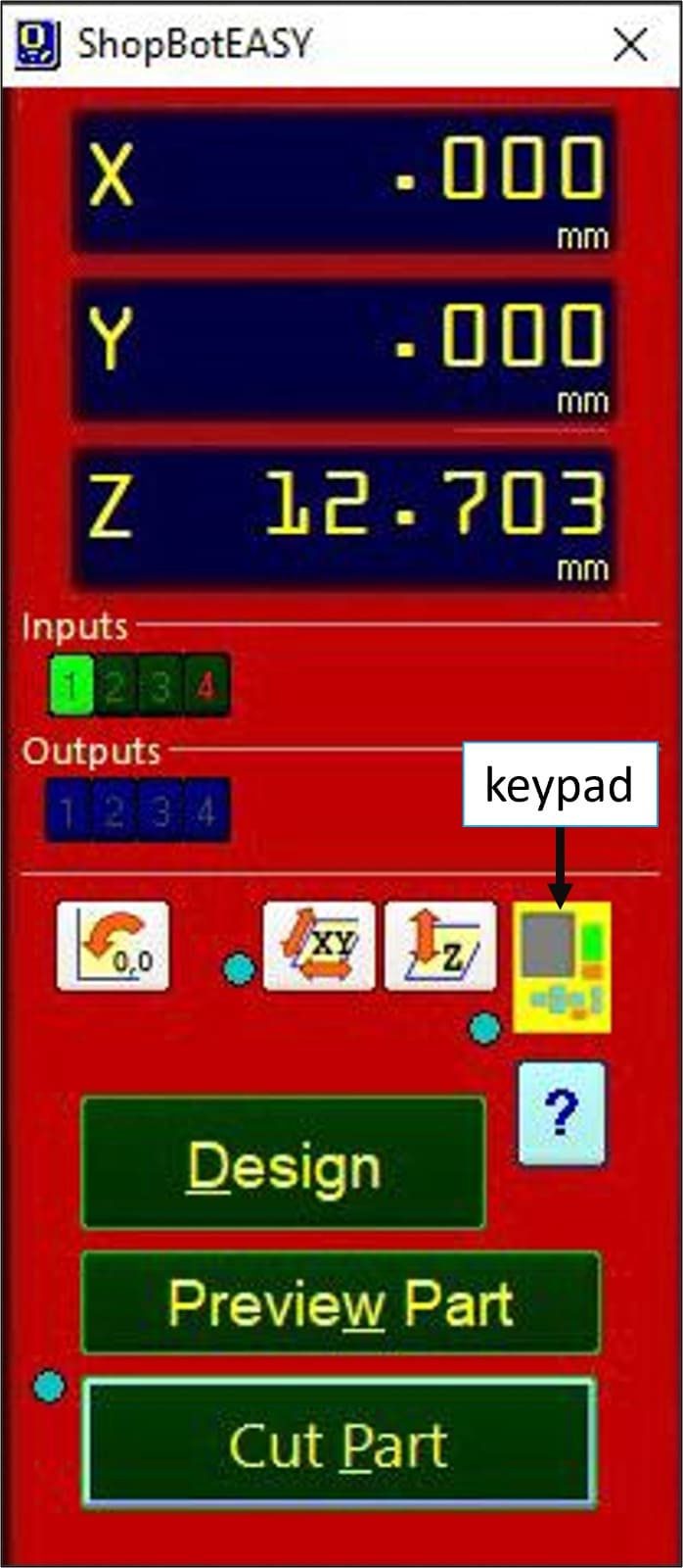
2. The spindle should be raised and moved to the "zero starting position.
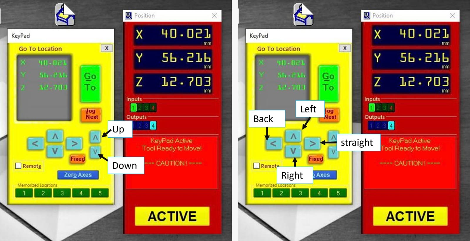
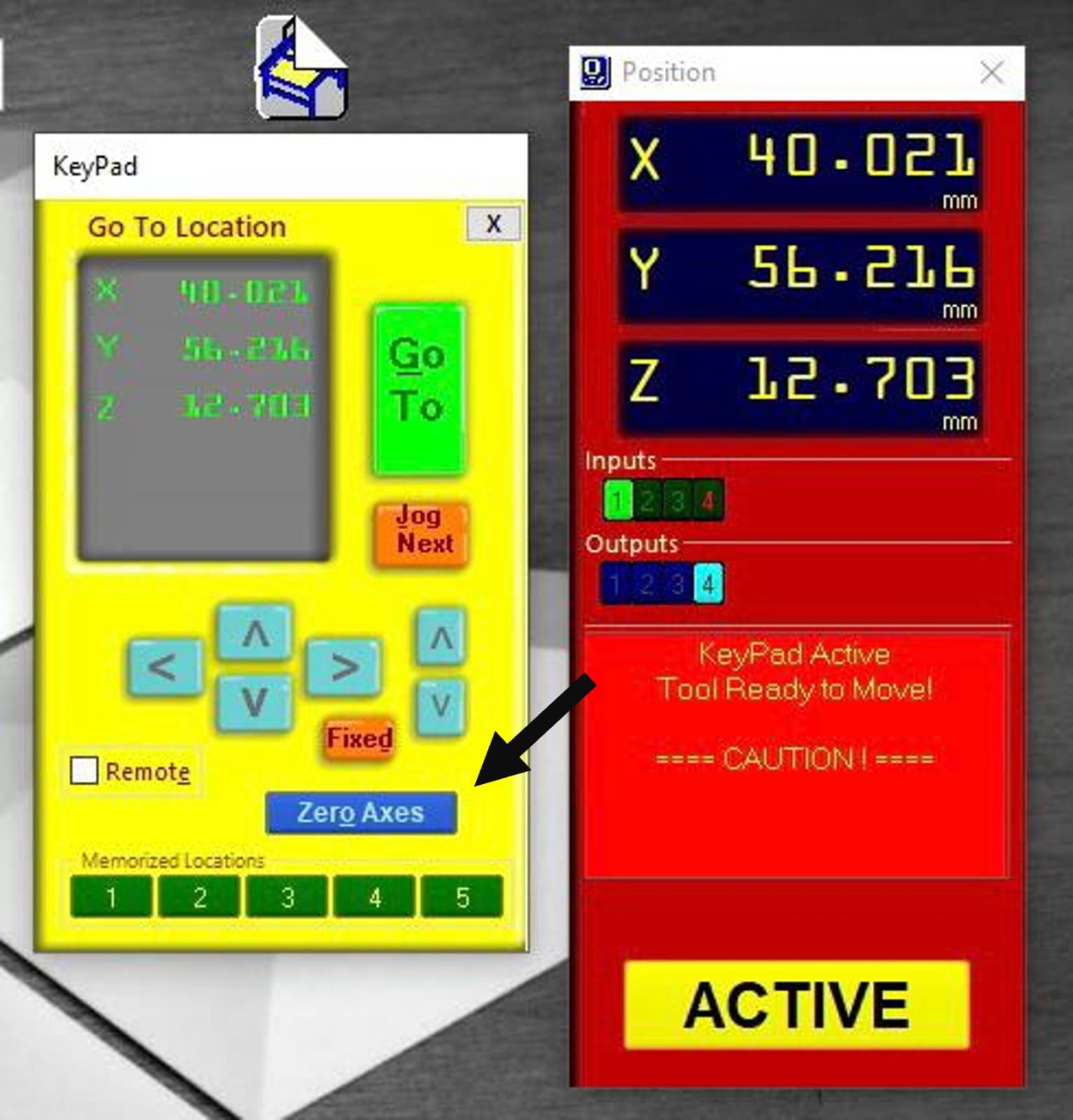
3. Reset your position to zero by clicking "Zero Axes then choose X and Y.
4. Pull the conductive plate up to calibrate the Z axis.

5. put the alligator clip in position.
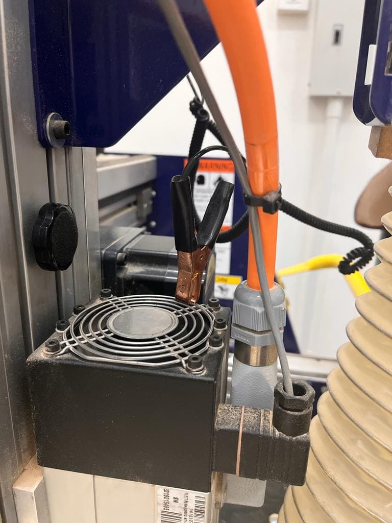
6. Underneath the drill bit, place the conductive plate.

7. Select the Z symbol.
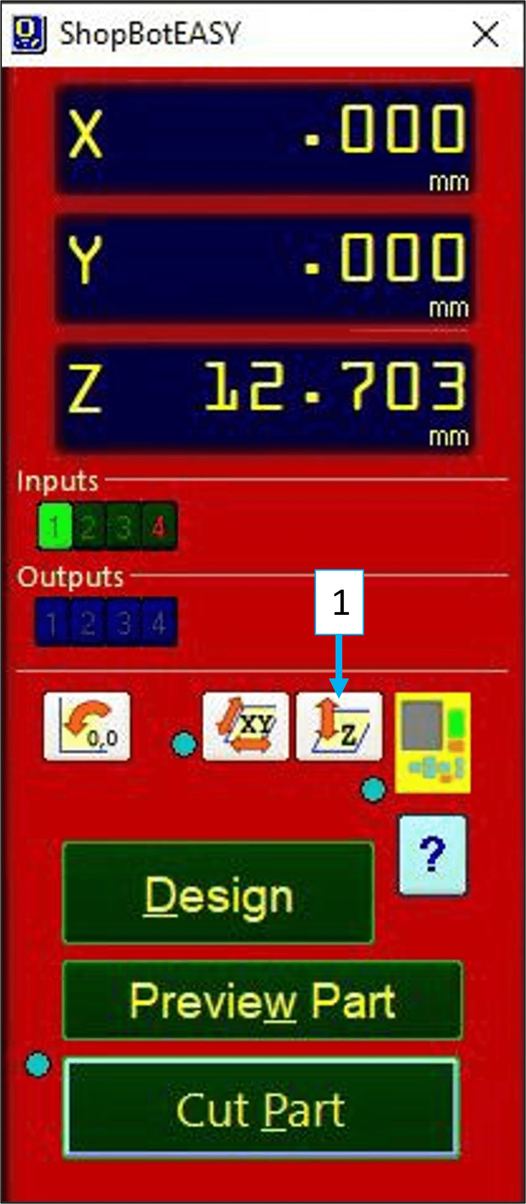
8. Check that your plate is properly positioned, then click OK.
9. Reposition the plate and fasten the alligator clamp to it.
Cutting
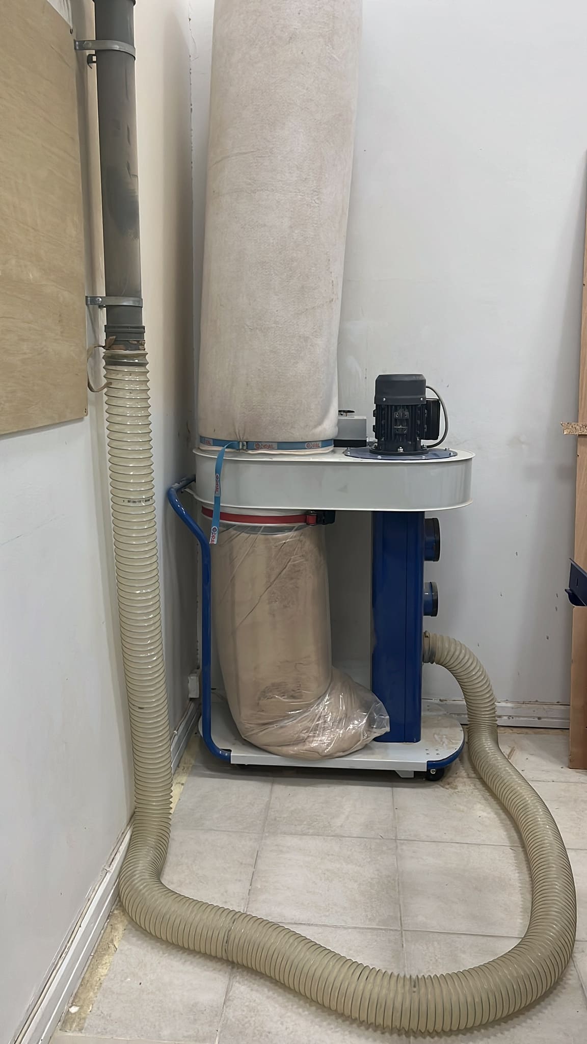
1. Switch ON the vacuume.
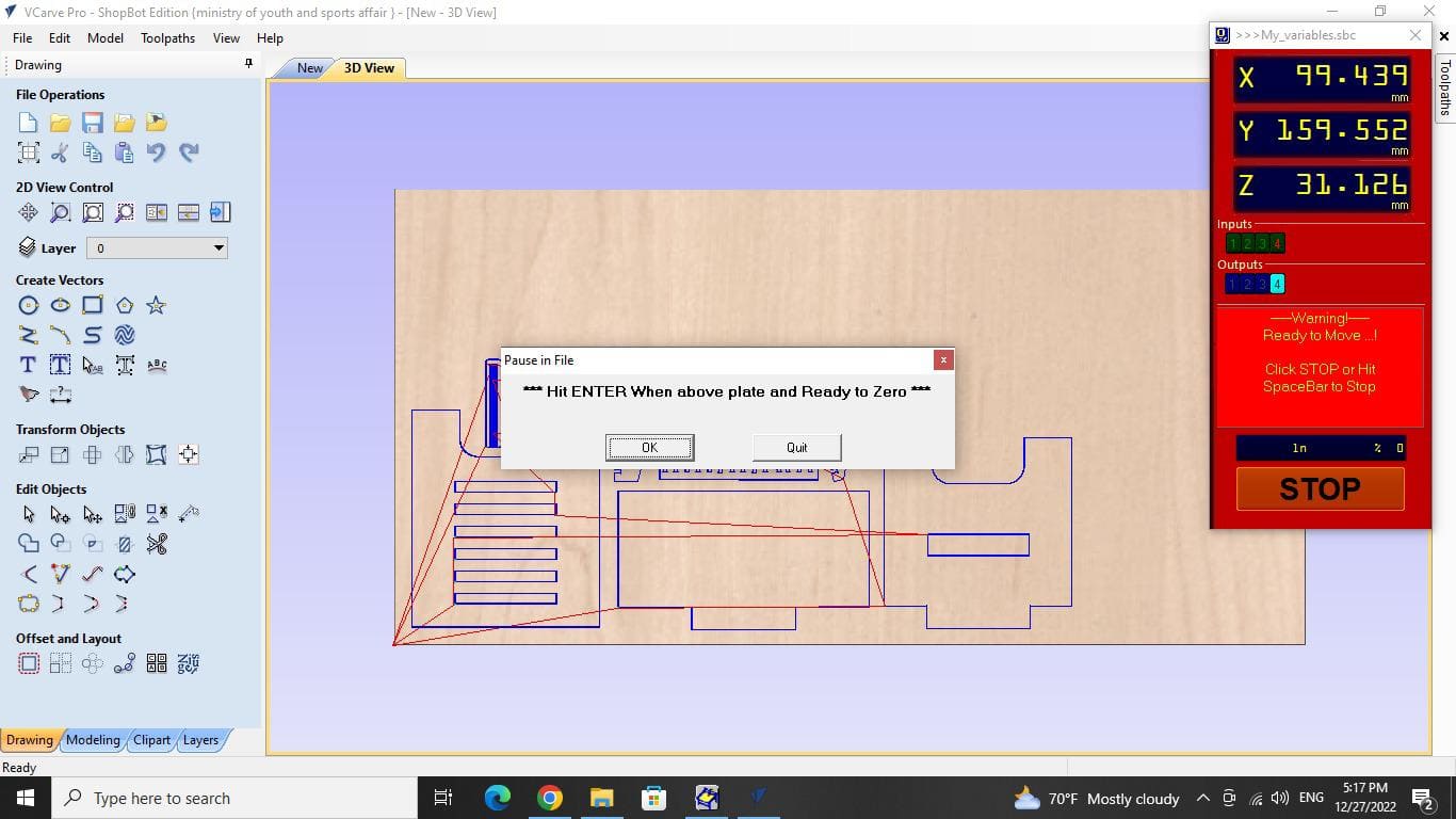
2. Head back to the computer and click cut parts, choose your file then hit start.
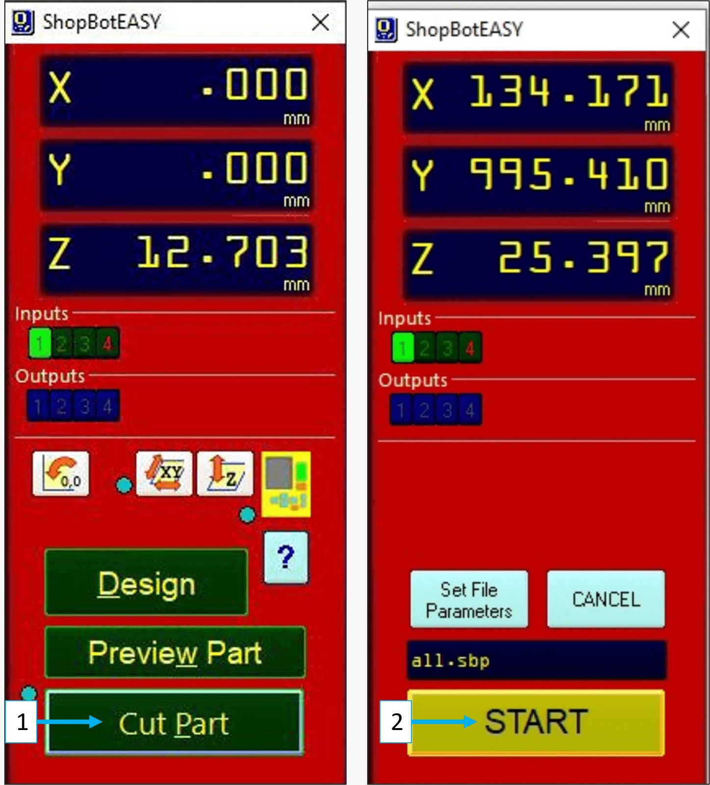
3. By holding down the start green button for three seconds, you will start the spindle.
4. Click OK.
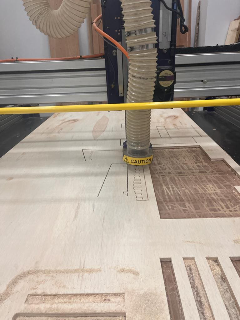
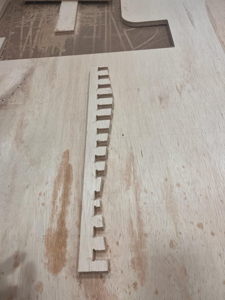
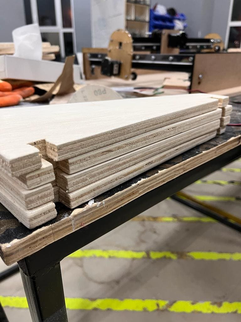
5. This is how it looked like after cutting.

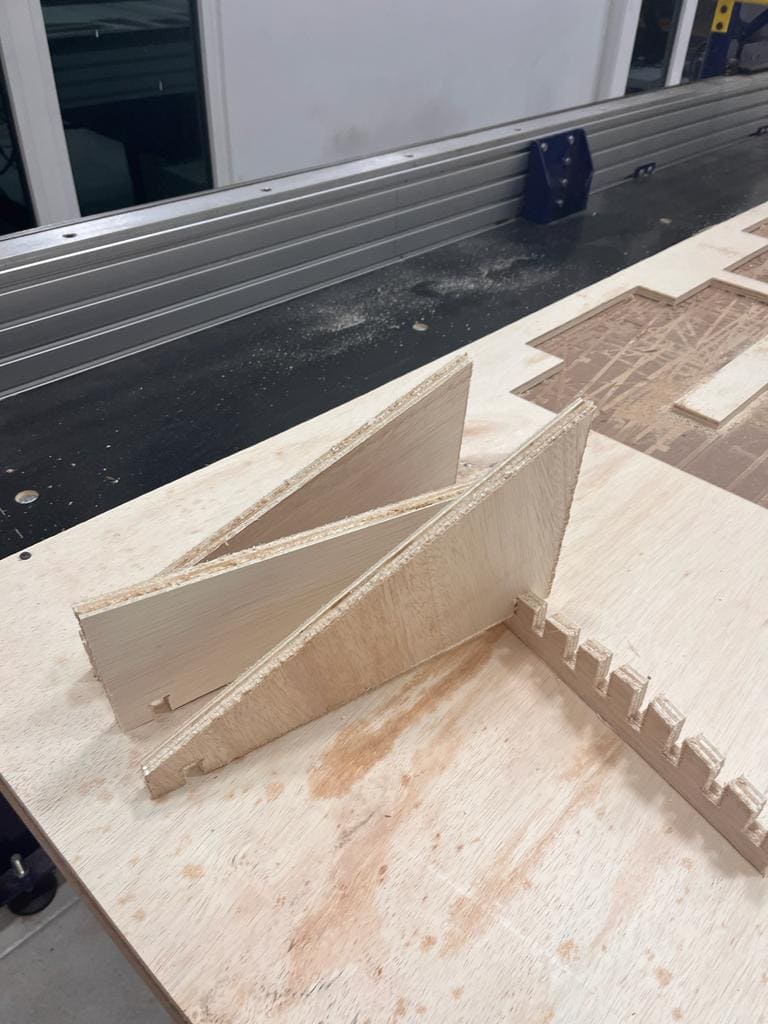
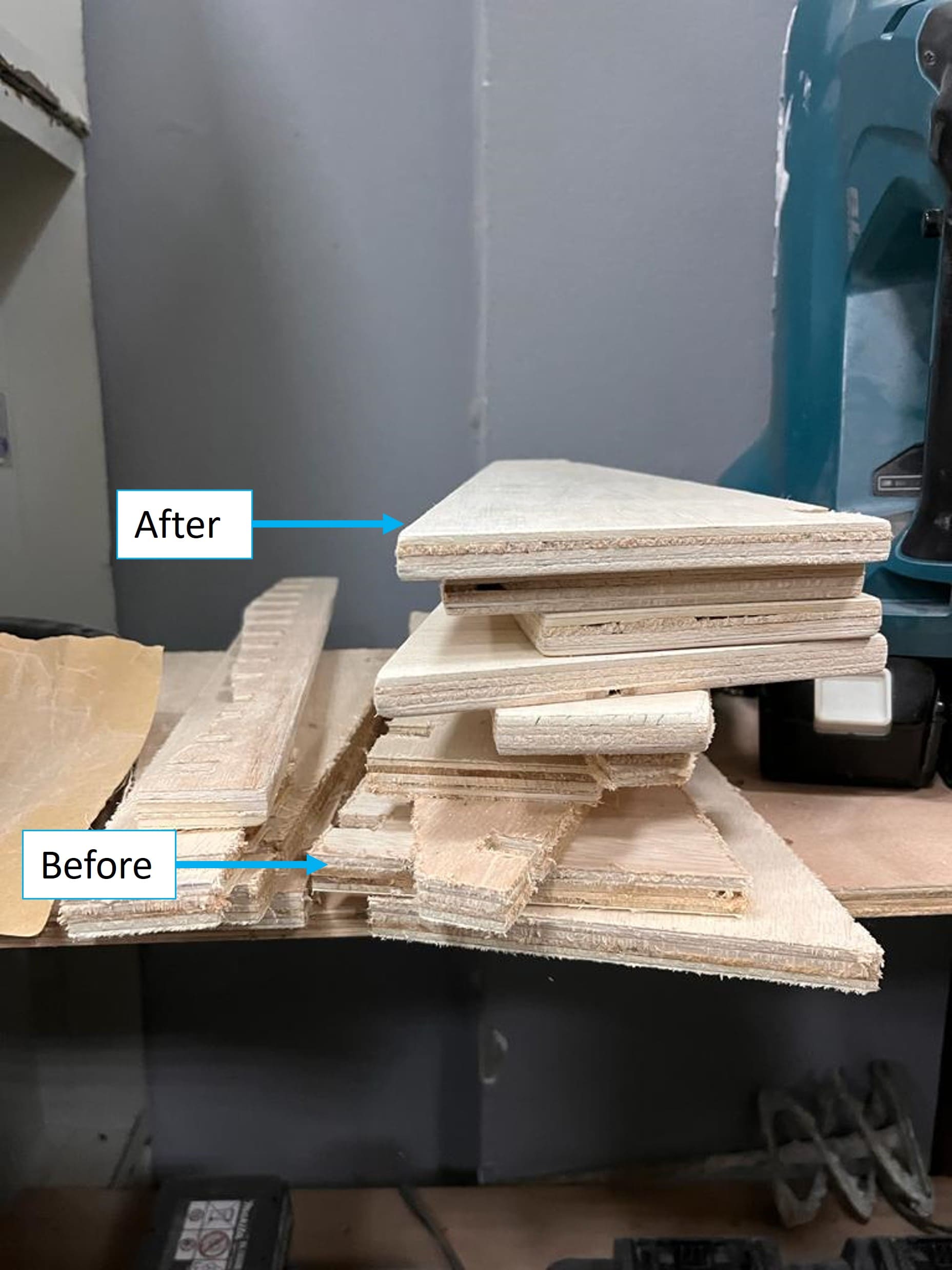
Wood finishing procedure
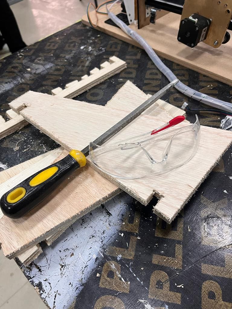
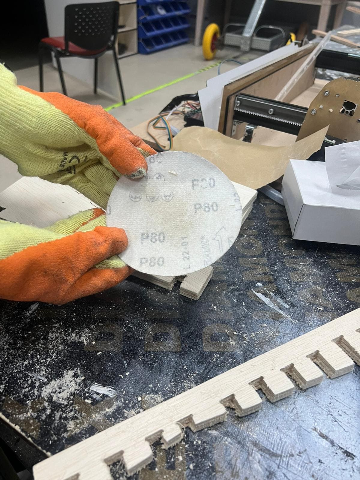
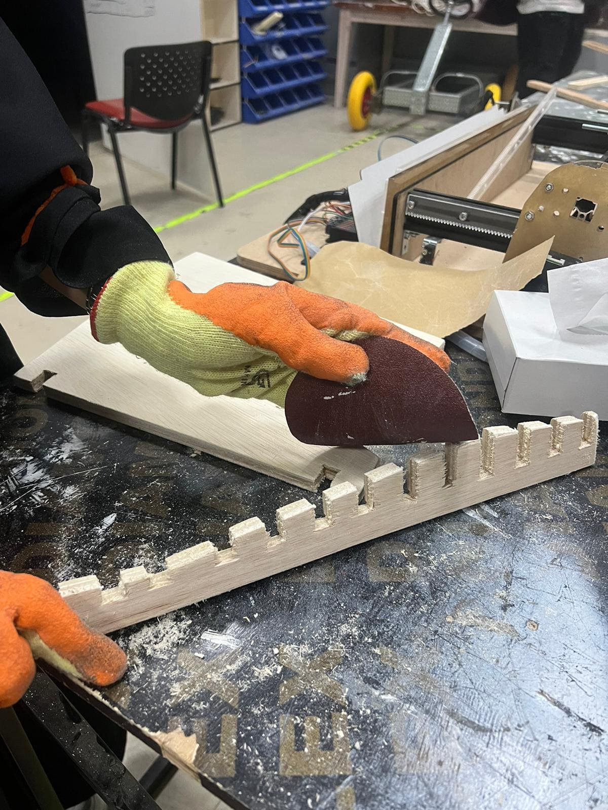
Sand the surface with paying specific attention to the edges and the gaps because you want a clear connection. Remove any additional chips with a file while moving with the grain of the wood to prevent it from breaking. To make it smoother, I first used P80 and then P150 sanding paper.
Attention!: wear protective glasses and a mask
Result
This is how it turned out

Files
🔗 Download Files
Fusion file
Body1
Body2
Body3
Body4
Body5
🔗 Resources
ShopBot
FabLabGuide
CNCRouterBits
04
Contact Me
Mobile Numberr
+973 35011840
sarahashiim18@gmail.com