Embedded Programming
The fourth week of the FabLab Academy program is about embedded programming. An embedded programming language is a programming language that developers use in embedded systems. The main objective of this week is to program a board.
Background
A microcontroller is an integrated circuit designed to govern a specific operation in an embedded system. A typical microcontroller includes a processor, memory and input/output peripherals on a single chip.
There are many types of microcontrollers. Each has different features and is used for a different purpose. Our team made the table below to illustrate the specifications of three mostly used types of microcontrollers.
| Criteria | Adafruit | Arduino | Bluefruit Sense |
|---|---|---|---|
| Power | 5V input 3.3V output | Typically works on 5V | 5V input 3.3V output |
| Pins | 6 input Read switches | 14 input/output | Power pins Logic pins and more! |
| Sensors | Force sensor Flow sensor | light sensor Sound sensor Air sensor Temperature sensor | Temperature sensor Motion sensor Sound sensor |
The second essential part is to program the microcontroller chip. To do so, there many languages that the programmer can use e.g. Python, C++. To find more about the different types of common programming languages, kindly visit Sarah’s page.
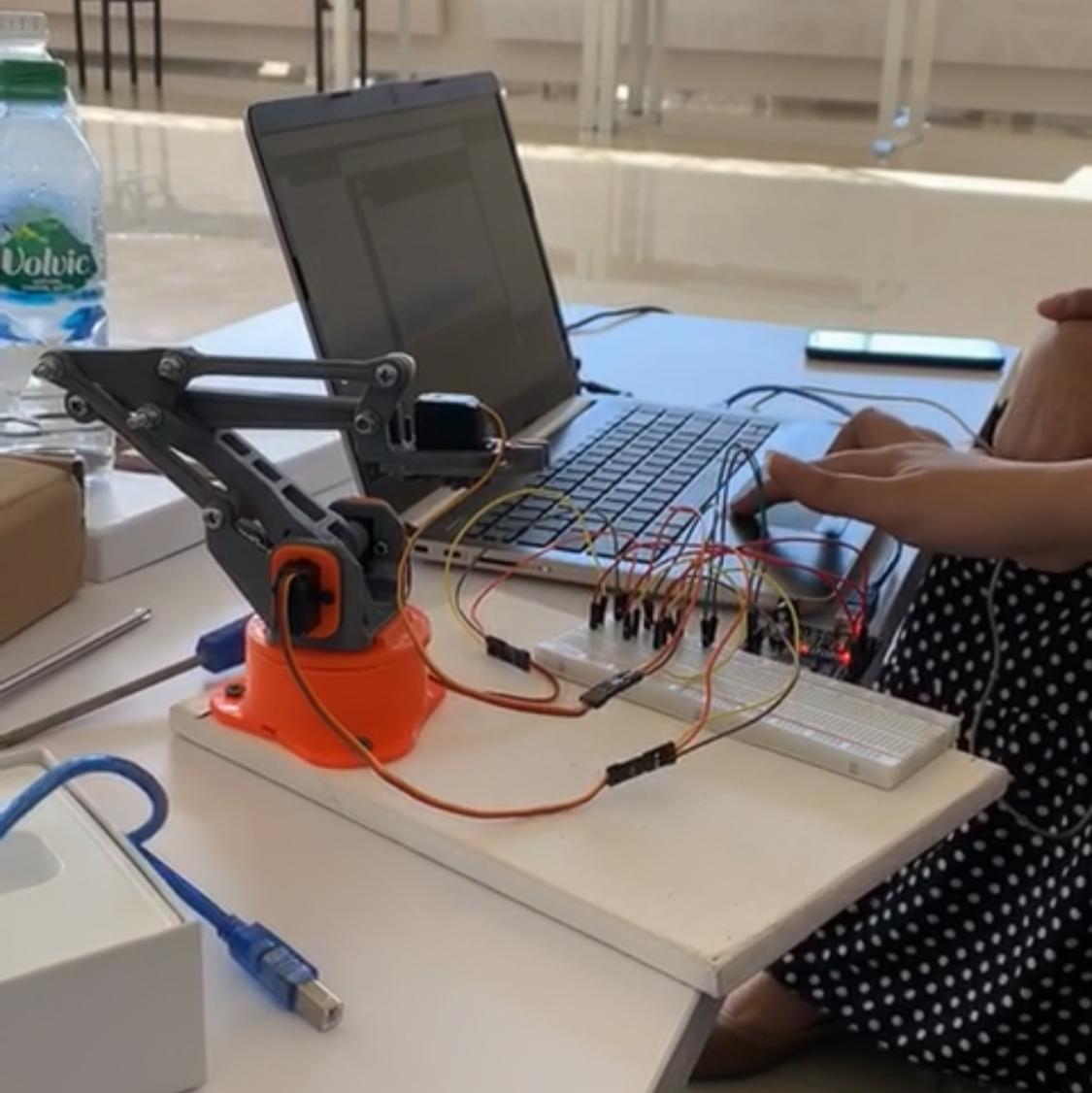
Personally, I am a bit familiar with programming using Arduino IDE software since I have worked with it in programming a 3D printed robotic arm controlled by leap sensors for my junior project back in university.
Arduino Software
Arduino is one of the best softwares for complete beginners to start with since it does not require complex coding or a background in programming.
Get started
In order to start programming, you need to install the software. Download Arduino IDE on your PC.
Now, after the software is successfully installed, you need to set up the software for Adafruit microcontroller, because the Arduino IDE is mainly used for Arduino microcontrollers. Follow the steps below to install the library for Adafruit, otherwise you will not be able to program your microcontroller.
-
Visit adafruit website
-
Copy the URL provided
https://adafruit.github.io/arduino-board-index/package_adafruit_index.json -
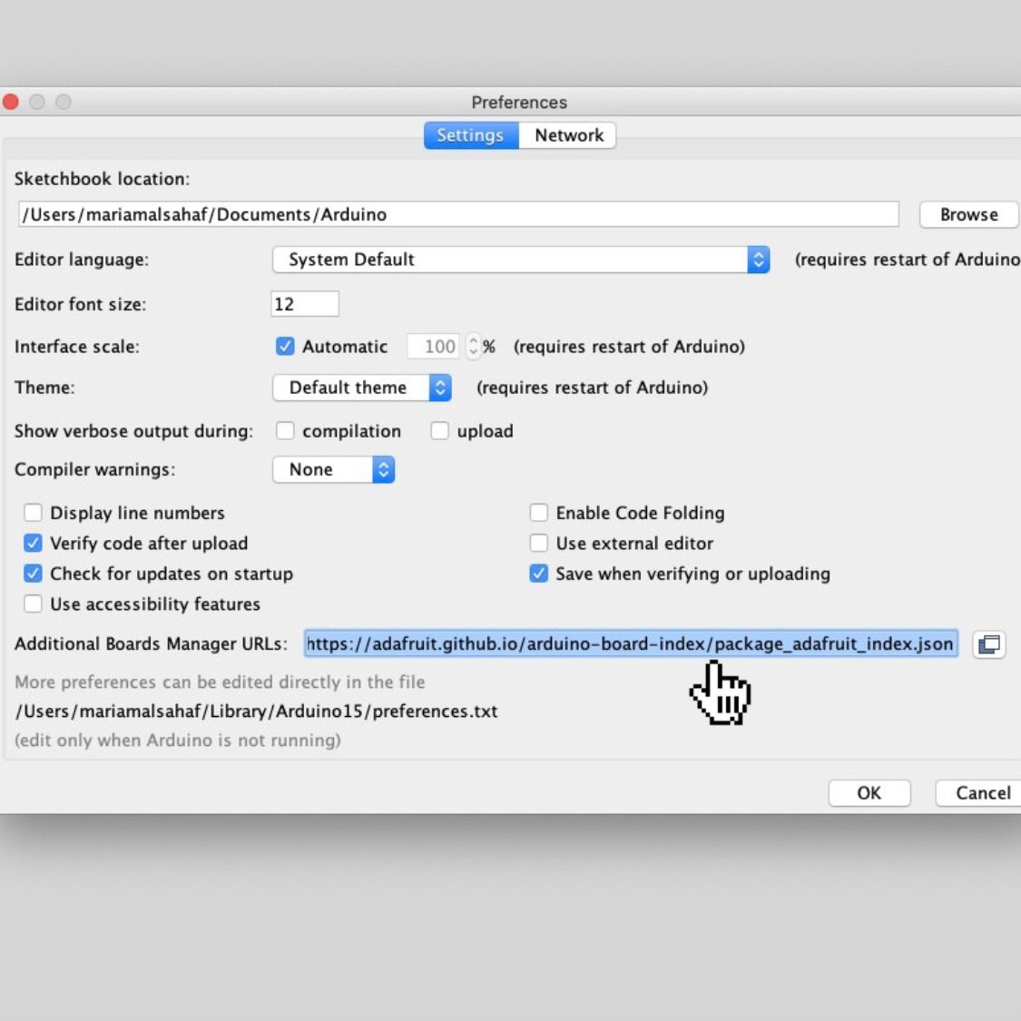
Open Arduino software
-
Go to Preferences > Additional Board Manager URLs, and paste the URL then press Ok
-
Go to Tools > Board > Board Manager
-
Type in the search box “Adafruit”
-
Look for adafruit nRF52, and press install

Note that if you are a MacOS user, your PC must be updated to the latest version - 11 or newer. Otherwise, you will not be able to upload the codes into the chip.
Here are some additional important notes for beginners:
- Void set-up is for the things that you need to identify when you are coding. Or like which pins are you going to use from the microcontroller.
- Define anything including libraries e.g. motors before that void set-up.
- Void loop is where you write the coding part.
Test your nRF52840
Before you dive into the sea of coding, it is recommended if for you to test your microcontroller chip first. Arduino make it easier by providing an auto-generated code called The Blink Code. It is basically a code that will make your microcontroller light turn on and off.
To try it, follow the next steps:
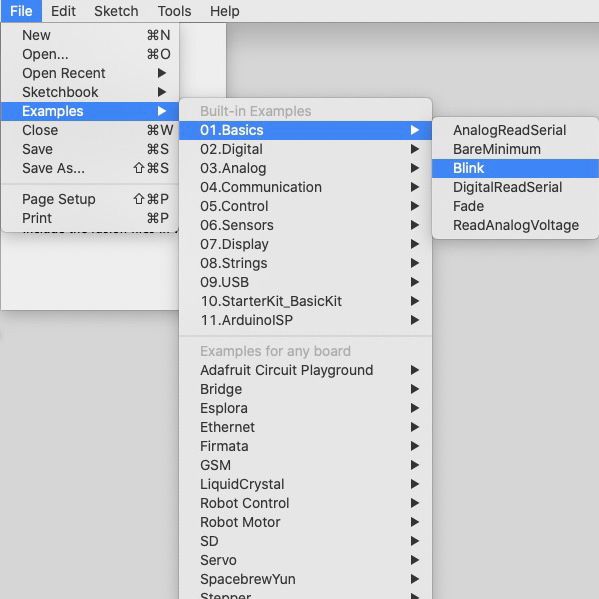
- Open Arduino
- Go to File > Basics > Examples > Blink
- Go to Tools > Board, and choose the adafruit you are working with

-
Connect your nRF52840 to the PC using a USB
-
Go to Tools > Port, and select your port

-
Open the Blink Coding page
-
Press the Upload button

- Congratulations! You must be able to see the adafruit blinking!
Morse Code
Morse code is a method used in telecommunication to encode text characters as standardized sequences of two different signal durations, called dots and dashes. The picture bellow illustrate the international morse code.

In order to use the morse code in programming, these are some tips:
. (1sec) ON
- (2sec) ON
Space between the same letter (0.5sec) OFF
Space between two letters (2sec) OFF
I wanted to write my initials using the Morse Code. I visited Morse Code Translator website to help me translate the word “MAS” into morse code.
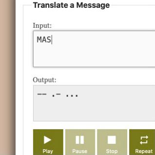
As it is shown above,
M in morse code is –
A in morse code is .-
S in morse code is …
Now, let us head straight to coding! I made a cheat sheet so I don’t get lost while coding.
# M
On 2sec                    # -
Off 0.5sec                 # space between the same letter
On 2sec                    # -
Off 2sec                   # space between two letters

# A
On 1sec                    #.
Off 0.5sec                 # space between the same letter
On 2sec                    # -
Off 2sec                   # space between two letters

# S
On 1sec                    # .
Off 0.5sec                 # space between the same letter
On 1sec                    # .
Off 0.5sec                 # space between the same letter
On 1sec                    # .
Off 0.5sec                 # space between the same letter
I used my cheat sheet to write the code on Arduino IDE. The following code represents my initials translated to morse code.
void setup() {
  // initialize digital pin LED_BUILTIN as an output.
  pinMode(LED_BUILTIN, OUTPUT);
}

// the loop function runs over and over again forever
void loop() {
  digitalWrite(LED_BUILTIN, HIGH);
  delay(2000);
  digitalWrite(LED_BUILTIN, LOW);
  delay(500);
  digitalWrite(LED_BUILTIN, HIGH);
  delay(2000);
  digitalWrite(LED_BUILTIN, LOW);
  delay(2000);
  digitalWrite(LED_BUILTIN, HIGH);
  delay(1000);
  digitalWrite(LED_BUILTIN, LOW);
  delay(500);
  digitalWrite(LED_BUILTIN, HIGH);
  delay(2000);
  digitalWrite(LED_BUILTIN, LOW);
  delay(2000);
  digitalWrite(LED_BUILTIN, HIGH);
  delay(1000);
  digitalWrite(LED_BUILTIN, LOW);
  delay(500);
  digitalWrite(LED_BUILTIN, HIGH);
  delay(1000);
  digitalWrite(LED_BUILTIN, LOW);
  delay(500);
  digitalWrite(LED_BUILTIN, HIGH);
  delay(1000);
  digitalWrite(LED_BUILTIN, LOW);
  delay(500);
After typing the code, I press the upload button to transfer the code to the adafruit chip and then run it.
Errors may occur! I have faced an error in running the code. The errors block in the Arduino IDE software indicates that my MacOS software needs to be upgraded to Captain 11. I am currently using Catalina 10. Therefore, I tried to download the newer version, but unfortunately, there was no enough space in my macbook.
Arduino in TinkerCAD
The Arduino simulation within TinkerCAD simplifies the programming experience. It is a free software. TinkerCAD Circuits provides a bottomless supply of virtual components that people can use to build and simulate their projects.
I opened my TinkerCAD profile and clicked on to create a circuit. Then, I chose the board that I want to work on, which is Arduino UNO. It is true that the actual board I am working with is Adafruit, but TinkerCAD does not have the Adafruit board within its system. Therefore, the most similar board available there is the Arduino UNO.

I opened the block page, and started building the morse code that I have used earlier. The Repeat block option is useful! It reduces the code’s length as it spares the programmer from repeating the same code multiple times.
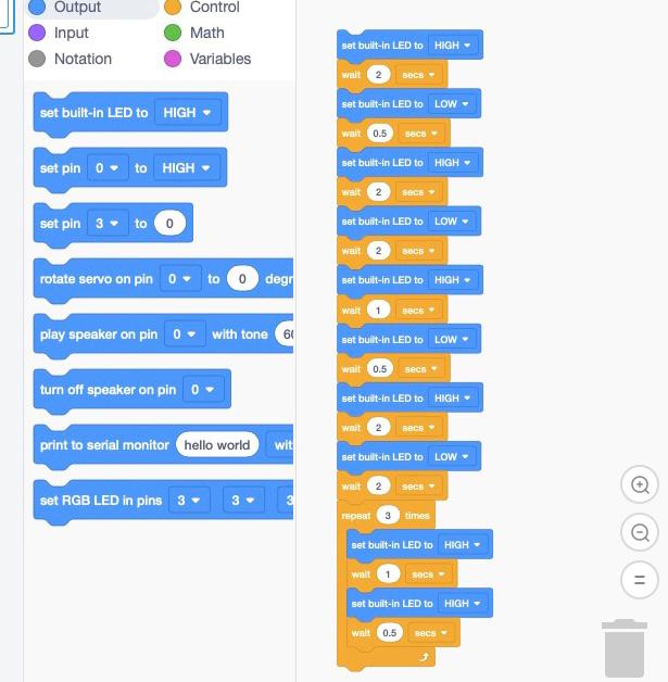
What is very interesting in TinkerCAD is the auto-generated code the creator can get whenever they design a circuit and the simulation. The auto-generated code feature is very helpful for those who are not familiar with programming. And the simulation spare the creator the time for testing in real-life and reduces the number of errors.
int counter;

void setup()
{
  pinMode(LED_BUILTIN, OUTPUT);
}

void loop()
{
  digitalWrite(LED_BUILTIN, HIGH);
  delay(2000); // Wait for 2000 millisecond(s)
  digitalWrite(LED_BUILTIN, LOW);
  delay(500); // Wait for 500 millisecond(s)
  digitalWrite(LED_BUILTIN, HIGH);
  delay(2000); // Wait for 2000 millisecond(s)
  digitalWrite(LED_BUILTIN, LOW);
  delay(2000); // Wait for 2000 millisecond(s)
  digitalWrite(LED_BUILTIN, HIGH);
  delay(1000); // Wait for 1000 millisecond(s)
  digitalWrite(LED_BUILTIN, LOW);
  delay(500); // Wait for 500 millisecond(s)
  digitalWrite(LED_BUILTIN, HIGH);
  delay(2000); // Wait for 2000 millisecond(s)
  digitalWrite(LED_BUILTIN, LOW);
  delay(2000); // Wait for 2000 millisecond(s)
  for (counter = 0; counter < 3; ++counter) {
    digitalWrite(LED_BUILTIN, HIGH);
    delay(1000); // Wait for 1000 millisecond(s)
    digitalWrite(LED_BUILTIN, LOW);
    delay(500); // Wait for 500 millisecond(s)
  }
}
By comparing the above code generated in TinkerCAD with the previous code in Arduino UNO, you can notice that the code in TinkerCAD is way shorter! That is all due to the usage of the repeat block also known as the for loop.
To conclude, TinkerCAD is a strong beneficial platform that has many interesting features. I would absolutely use it on my final project as it reduces the time consumed in getting the right functional code.
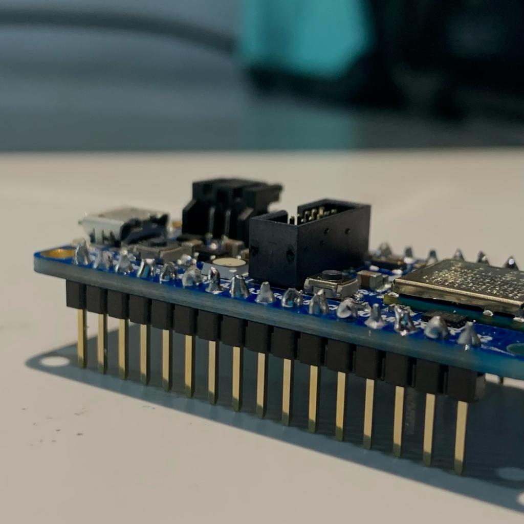
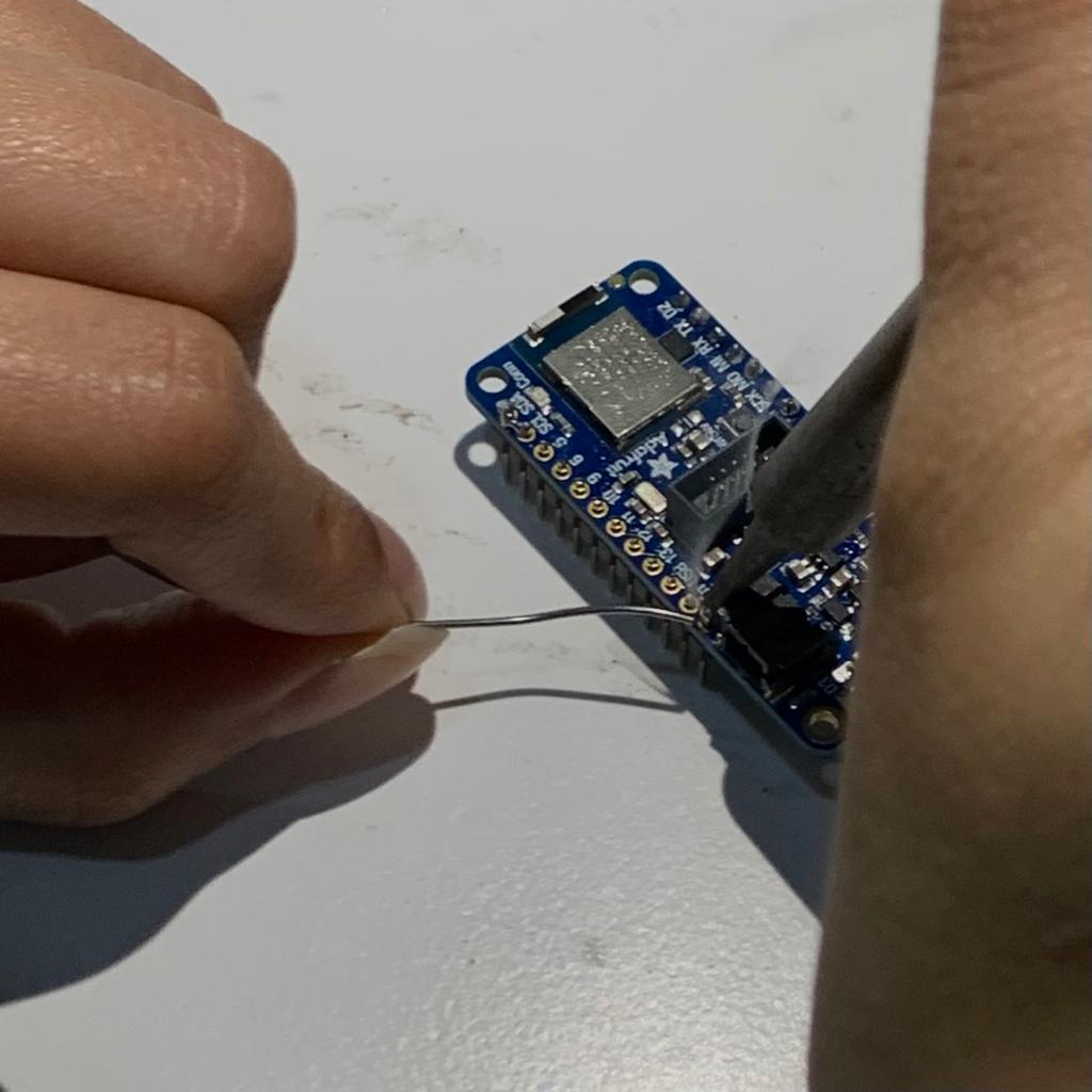
Soldering Adaruit nRF52840
Soldering is a process that is used to join different metal types/pats together. Soldering is not the same as welding nor brazing, for further info, check this website.
The soldering process consists of several tools mentioned below:
- Soldering Iron and Wire
This is the main tool in soldering. It operates at high temperature above the melting point of the metal as it melts the metal (soldering wire) to join the different parts/types. To keep the cleanliness of this tool, a wet sponge is used to clean the soldering iron tip prior soldering components.
- Solder suckers
Used to removed the excess solder to re-shape.
- Fumes Absorber
Due to the high temperature used to melt the metal, an excessive fumes are generated. The user is instructed not to breath next while soldering to prevent inhaling those dangerous fumes that could effect the lungs and cause a serious issue.

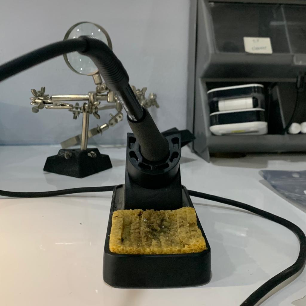
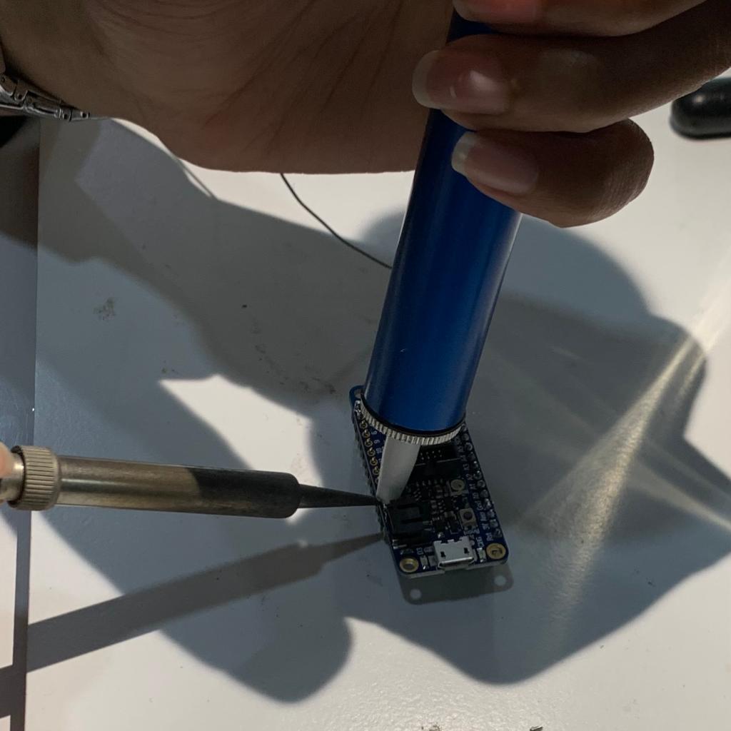
Soldered Chip
The whole process of soldering the chip took about twenty minutes. I had to solder some of the joints all over again and the fumes were very disturbing. But as an overall experience as the first time, it was a good easy one.