4. Embedded programming
This week is more of the electrical side where we get introduced to programming.
What is a Microcontroller?
A microcontroller is a compact integrated circuit designed to govern a specific operation in an embedded system. A typical microcontroller includes a processor, memory and input/output (I/O) peripherals on a single chip.
Group research : Comparing different programming languages and how many languages can be used in one microcontroller.
| Language | Characteristics | Pros | Cons |
|---|---|---|---|
| C | Compiled language, very useful & powerful. Base for many scripting languages. Best choice for beginners. | Efficient & widely used. Very less runtime. | Makes system insecure. |
| C++ | Compiled language, it has most or all elements of C. Supports different ways of programming like procedural, object-oriented. | Efficient & can save time in writing codes. | Most complicated. |
| Python | A general-purpose interpreted, interactive, object-oriented, and high-level programming language. Excels in machine learning, AI, data analytics. | Open source, easy to learn. | Not for real time operating systems. |
| MicroPython | Runs on the bare metal of the microprocessors. Smaller version of Python standard library. | Human readable, built-in exception and error handling. | Takes more memory. No editor. |
-
5-6 languages can be used to program one microcontroller.
-
To know more about the specifications of three most used microcontrollers, visit Maryam’s page.
ARDUINO IDE
Arduino Software (IDE) makes it easy to write code and upload it to the board.
Steps to get started and a small tutorial to “Blink”
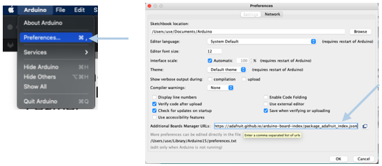
-
Copy the link
https://adafruit.github.io/arduino-board-index/package_adafruit_index.json -
Go to Arduino > Preferences > Paste the link > OK.
-
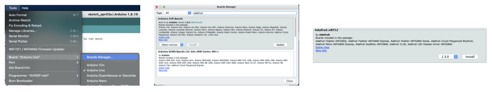
Go to Tools > Boards > Boards Manager.
-
Search for Adafruit > Install Adafruit nRF52.
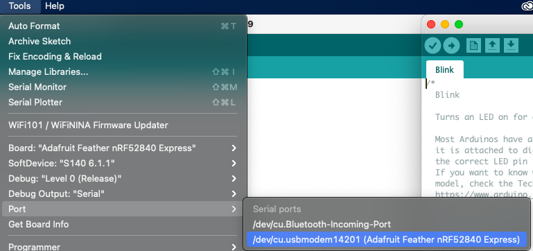
Blink Tutorial
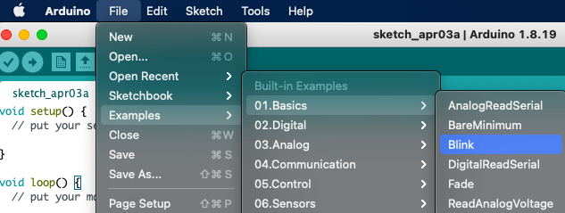
- Connect your microcontroller to your laptop.

- Go to File > Examples > Blink.
- Choose the board of the microcontroller you are using, go to Tools > Board > Adafruit nRF52 boards > Adafruit Feather.
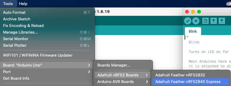
- Port in the microcontroller, go to Tools > Port > (Choose the microcontroller)
you can now change the seconds of on & off blinking in the sheet.
Morse Code Exercise
Morse code is a method used in telecommunication to encode text characters as standardized sequences of two different signal durations, called dots and dashes, or dits and dahs.
To translate morsecode, visit Morse Code Translator
Fablab Code Rules for Morse Code Excercise
| Code | Seconds | ON/OFF |
|---|---|---|
| . | One | ON |
| - | Two | ON |
| Space in the same letter | Half | OFF |
| Space between two letters | Two | OFF |
Translating “Sara” in Morse code :
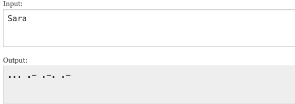
Following the code rules :
// the setup function runs once when you press reset or power the board
void setup() {
  // initialize digital pin LED_BUILTIN as an output.
  pinMode(LED_BUILTIN, OUTPUT);
}

// the loop function runs over and over again forever
void loop() {
  digitalWrite(LED_BUILTIN, HIGH);   // turn the LED on (HIGH is the voltage level)
  delay(1000);                       // wait for a second
  digitalWrite(LED_BUILTIN, LOW);    // turn the LED off by making the voltage LOW
  delay(500);                       // wait for a second
    digitalWrite(LED_BUILTIN, HIGH);   // turn the LED on (HIGH is the voltage level)
  delay(1000);                       // wait for a second
  digitalWrite(LED_BUILTIN, LOW);    // turn the LED off by making the voltage LOW
  delay(500);                       // wait for a second
    digitalWrite(LED_BUILTIN, HIGH);   // turn the LED on (HIGH is the voltage level)
  delay(1000);                       // wait for a second

  digitalWrite(LED_BUILTIN, LOW);    // turn the LED off by making the voltage LOW
  delay(2000);                       // wait for a second

    digitalWrite(LED_BUILTIN, HIGH);   // turn the LED on (HIGH is the voltage level)
  delay(1000);                       // wait for a second
  digitalWrite(LED_BUILTIN, LOW);    // turn the LED off by making the voltage LOW
  delay(2000);                       // wait for a second

    digitalWrite(LED_BUILTIN, HIGH);   // turn the LED on (HIGH is the voltage level)
  delay(2000);                       // wait for a second

  digitalWrite(LED_BUILTIN, LOW);    // turn the LED off by making the voltage LOW
  delay(1000);                       // wait for a second
    digitalWrite(LED_BUILTIN, HIGH);   // turn the LED on (HIGH is the voltage level)
  delay(2000);                       // wait for a second
  digitalWrite(LED_BUILTIN, LOW);    // turn the LED off by making the voltage LOW
  delay(1000);                       // wait for a second

    digitalWrite(LED_BUILTIN, HIGH);   // turn the LED on (HIGH is the voltage level)
  delay(2000);                       // wait for a second

  digitalWrite(LED_BUILTIN, LOW);    // turn the LED off by making the voltage LOW
  delay(1000);                       // wait for a second
    digitalWrite(LED_BUILTIN, HIGH);   // turn the LED on (HIGH is the voltage level)
  delay(2000);                       // wait for a second

    digitalWrite(LED_BUILTIN, LOW);    // turn the LED off by making the voltage LOW
  delay(500);                       // wait for a second
}
After typing the code, click on Upload.

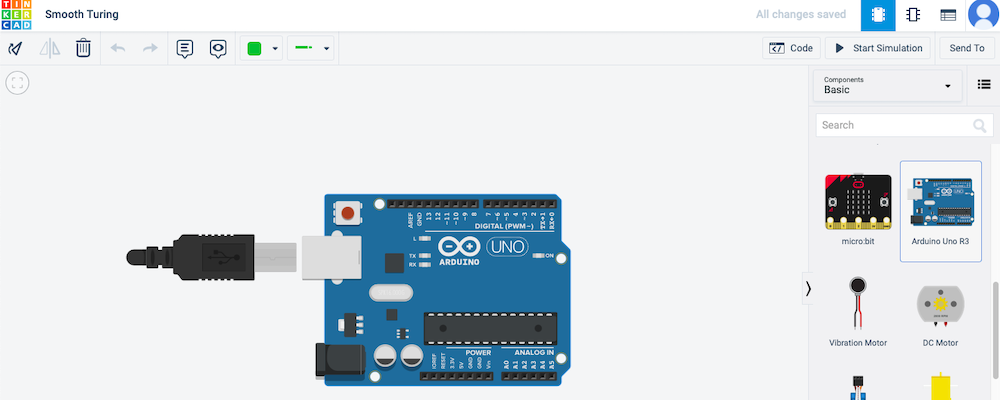
TinkerCAD
TinkerCAD has a circuits feature where you can edit, code and test your microcontroller online.
TinkerCAD is actually a bit easier than arduino itself (to me ofc) because I can test the code online before uploading it to my microcontroller directly which saves time.
To start circuits in TinkerCAD : Log in to TinkerCAD and click on Circuits > Create new Circuit.
This is a breif of how things work in this software.
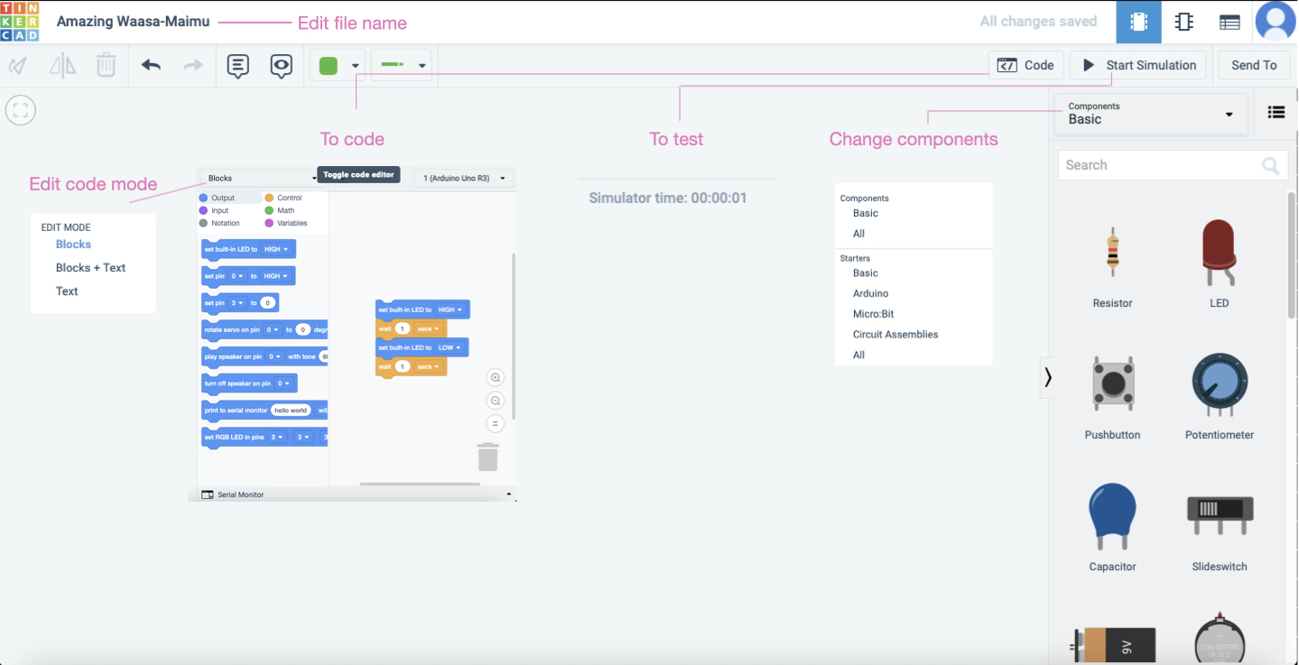
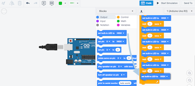
There are so many components, when you go to Basics you’ll find your microcontroller now you can drag it to work on it. Unfortunately Adafruit is not available in this software so instead I chose to work on Arduino UNO.
The blink code is already done in TinkerCAD, once you click on code after dragging the Arduino UNO the blink code will appear.
Blink OFF, go to Control > drag Wait.
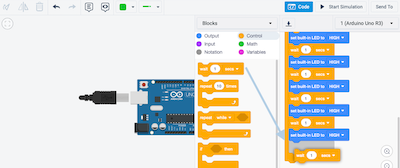
Blink ON, go to Output > drag LED High.
Change seconds according to your preference.
Audio Piezo
A piezo buzzer is a type of electronic device that’s used to produce a tone, alarm or sound.
After creating a new circuit in TinkerCAD, Add the audio piezo to the circuit.
Connect the piezo to the circuit according to the specific pin in the code.
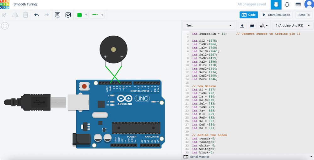
Paste the code in Text Code.
Bella Ciao Buzzer Music.
/*

int BuzzerPin = 11;     // Connect Buzzer to Arduino pin 11

int Si2 =1975;
int LaS2=1864;
int La2= 1760;
int SolS2=1661;
int Sol2=1567;
int FaS2=1479;
int Fa2= 1396;
int Mi2= 1318;
int ReS2=1244;
int Re2= 1174;
int DoS2=1108;
int Do2= 1046;

// Low Octave
int Si = 987;
int LaS= 932;
int La = 880;
int SolS=830;
int Sol= 783;
int FaS= 739;
int Fa=  698;
int Mi=  659;
int ReS= 622;
int Re = 587;
int DoS =554;
int Do = 523;

// define the notes
int rounda=0;
int roundp=0;
int white= 0;
int whitep=0;
int black=0;
int blackp=0;
int quaver=0;
int quaverp =0;
int semiquaver=0;
int semiquaverp=0;
int bpm= 120;

void setup(){
      pinMode(BuzzerPin,OUTPUT);

      black= 35000/bpm;
      blackp=black*1.5;
      white= black*2;
      whitep=white*1.5;
      rounda= black*4;
      roundp= rounda*1.5;
      quaver= black/2;
      quaverp=quaver*1.5;
      semiquaver= black/4;
      semiquaverp=semiquaver*1.5;
}
void loop(){
  tone(BuzzerPin,Mi,black);
  delay(black+50);
  tone(BuzzerPin,La,black);
  delay(black+50);
  tone(BuzzerPin,Si,black);
  delay(black+50);
  tone(BuzzerPin,Do2,black);
  delay(black+50);
  tone(BuzzerPin,La,black);

  delay(2*white+50);

  tone(BuzzerPin,Mi,black);
  delay(black+50);
  tone(BuzzerPin,La,black);
  delay(black+50);
  tone(BuzzerPin,Si,black);
  delay(black+50);
  tone(BuzzerPin,Do2,black);
  delay(black+50);
  tone(BuzzerPin,La,black);

  delay(2*white+50);

  tone(BuzzerPin,Mi,black);
  delay(black+50);
  tone(BuzzerPin,La,black);
  delay(black+50);
  tone(BuzzerPin,Si,black);
  delay(black+50);
  tone(BuzzerPin,Do2,white*1.3);
  delay(2*black+50);

  tone(BuzzerPin,Si,black);
  delay(black+50);
  tone(BuzzerPin,La,black);
  delay(black+50);
  tone(BuzzerPin,Do2,white*1.3);
  delay(2*black+50);

  tone(BuzzerPin,Si,black);
  delay(black+50);
  tone(BuzzerPin,La,black);
  delay(black+50);
  tone(BuzzerPin,Mi2,black);
  delay(white+50);
  tone(BuzzerPin,Mi2,black);
  delay(white+100);

  tone(BuzzerPin,Mi2,black);
  delay(white+50);
  tone(BuzzerPin,Re2,black);
  delay(black+50);
  tone(BuzzerPin,Mi2,black);
  delay(black+50);
  tone(BuzzerPin,Fa2,black);
  delay(black+50);
  tone(BuzzerPin,Fa2,white*1.3);
  delay(rounda+100);

  tone(BuzzerPin,Fa2,black);
  delay(black+50);
  tone(BuzzerPin,Mi2,black);
  delay(black+50);
  tone(BuzzerPin,Re2,black);
  delay(black+50);
  tone(BuzzerPin,Fa2,black);
  delay(black+50);
  tone(BuzzerPin,Mi2,white*1.3);
  delay(rounda+100);

  tone(BuzzerPin,Mi2,black);
  delay(black+50);
  tone(BuzzerPin,Re2,black);
  delay(black+50);
   tone(BuzzerPin,Do2,black);
  delay(black+50);
  tone(BuzzerPin,Si,white*1.3);
  delay(white+50);
  tone(BuzzerPin,Mi2,white*1.3);
  delay(white+50);
  tone(BuzzerPin,Si,white*1.3);
  delay(white+50);
  tone(BuzzerPin,Do2,white*1.3);
  delay(white+50);
  tone(BuzzerPin,La,rounda*1.3);
  delay(rounda+50);

}
Soldering
Soldering pen fix
Pictures of the process :
The space


Fixing solders

Hero Shot :sparkles:
