Industrial project (microfludic chip)
What is microfluidics?
Microfluidics is considered as the science that studies the behavior and the properties of the fluid that flow through the micro channels. and also the technology of manufacturing the micro devices where these devices contain chambers and tunnels through which fluids flow. The microfluidics deal with very small volume of fluids and this allows and helps to do the controlling and manipulating the fluids.
How do microfluidics work?
- The system of microfluidics works by using a pump and a chip (microfluidic chip).
- Basically, this chip is a device that enables a tiny amount of liquid to be visualized.
- Furthermore, we have different types of pumps depend on the liquid flow rate inside the chip.
- Inside this chip there are channels that allow the processing of liquid ( i.e mixing, chemical reactions and so on).
- Sometime the liquid may carry very small particles (i.e catalyst) and the microdevices will enable theses to process.
Applications:
-
Lab-on-a-chip: A lab-on-a-chip (LOC) is a device performing on a miniaturized scale one or several analyses commonly carried out in a laboratory. It integrates and automates multiple high-resolution laboratory techniques such as fluid testing into a system that fits on a chip. Fluids behavior at this scale makes it easier to control the movement and interaction of samples, causing reactions to be much more potent, and minimizing chemical waste. It also allows reduces exposure to dangerous chemicals.
-
Organs on chips: Organs on chips are 3D cell culture microdevices aiming to reproduce the key functions of living organs on a computer chip. Organs on chips use microfluidics and microfabrication technologies to replicate the functionalities of living organs. There are models such as,gut on a chip, heart on a chip, liver on a chip, lung on a chip, tumor on a chip, muscle on a chip, multiple organs on a chip.
-
Microfluidics enables applications in agriculture and animal sciences such as: -Nutrients monitoring and plant cells sorting for improving crop quality and production. -Effective delivery of biopesticides. -Simplified in vitro fertilization for animal breeding. -Animal health monitoring. -Vaccination and therapeutics.
Flow of Fluid
- the flow of fluid through a microfluidic characterised by Re “Reyold number” : Re=LVp/u
where - L:length scale - u: viscosity - p: fluid density - V: average velocity - and L=4A/P
where A: cross sectional area of the channel P: wetted perimeter of the channel
Microfluidic technology:
which refers to the control and manipulation of fluids in the range of micro to picolitres, has been coupled with paper-based devices to create advanced sensors with guided fluid flow for the detection of clinical markers.
low-cost material
In the early stage of microfluidics, glass and silicon were the most commonly used materials. Silicon and glass materials are expensive, rigid, and brittle, which makes them hard to process. glass and silicon were soon largely replaced with low-cost materials, e.g. polymer and paper.
Currently, more organic and inorganic materials have been used in the fabrication of low-cost microfluidics such as elastomers, thermal plastics, thermosets, paper, and bio-materials.
Low-cost fabrication methods
- C02 laser (used for different materials such as PMMA and stainless steel).
- Mechanical microcutting technology using high-precision computer numerical control (CNC) milling machine utilizes different drill bit sizes to perform the drilling subtractive process.
- 2D/3D printing
2D and 3D Modeling
Add here your modeling and design.
Identify different low-cost techniques for microfluidic concepts, identify sourced materials and portable fab lab tools and design educational materials around it.
the “craft cutter” can consistently achieve microchannels as thin as 200 mm in width and can be used to fabricate three-dimensional (3D) microfluidic devices in minutes without the need of expensive equipment.

- advanteges:
- much less expensive.
- safe.
- portable.
- very user friendly.
-
rapid prototyping method.
-
material:
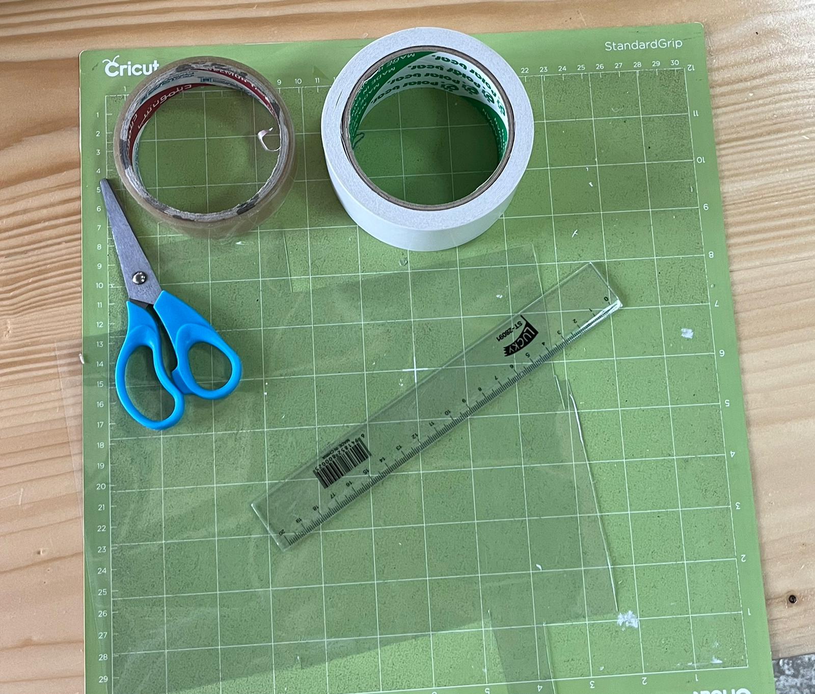
- desktop digital craft cutter.
- double-sided pressure sensitive adhesive (PSA) tape.
- laser printer transparency film (reusable cutting mat).
-
plastic layers.
-
procedure:
- first customize the microfluidic device onto the cutter software
- Then the craft cutter cut the design out from a double-sided PSA tape (50 mm thick PSA layer sandwiched between two 50 mm thick plastic protective layers) that was adhered onto the repositionable adhesive surface of a reusable cutting mat
- the cut double sided PSA tape was still adhered onto the reusable cutting mat, the cut pattern was carefully removed using a tweezers.
- the top protective layer of the cut double-sided PSA tape was peeled away revealing the top permanent adhesive surface.
- Then, a 100 mm thick laser printer transparency film was pressed onto the top permanent adhesive surface.
- After that the whole assembly was peeled away from the reusable cutting mat.
- Inlet and outlet holes were punched before flipping the assembly over and peeling away the bottom protective layer of the cut double-sided PSA tape revealing the bottom permanent adhesive surface.
- Finally, a second transparency film was pressed onto the bottom permanent adhesive surface to complete the working device.
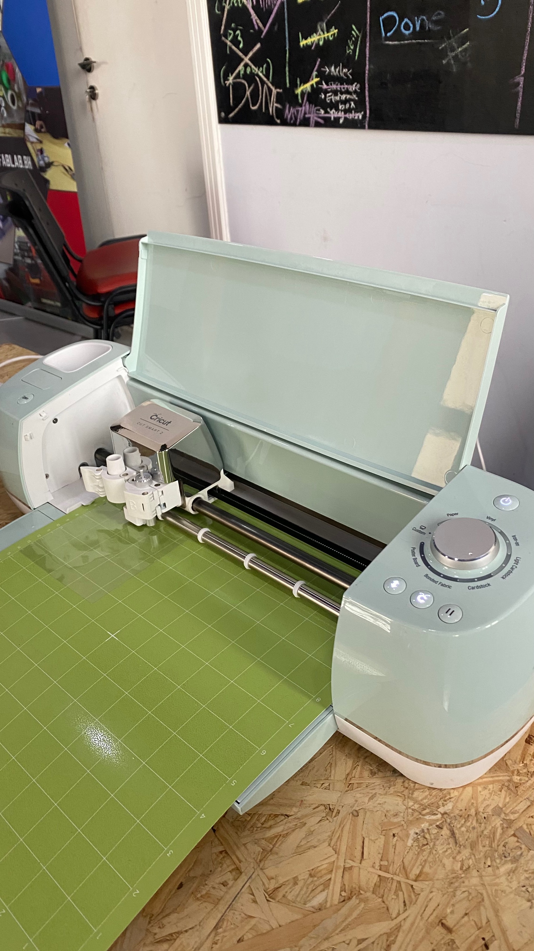
testing Cricut Explore Air 2 DIY cutting machine
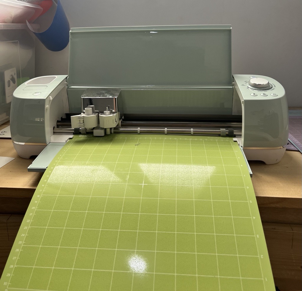
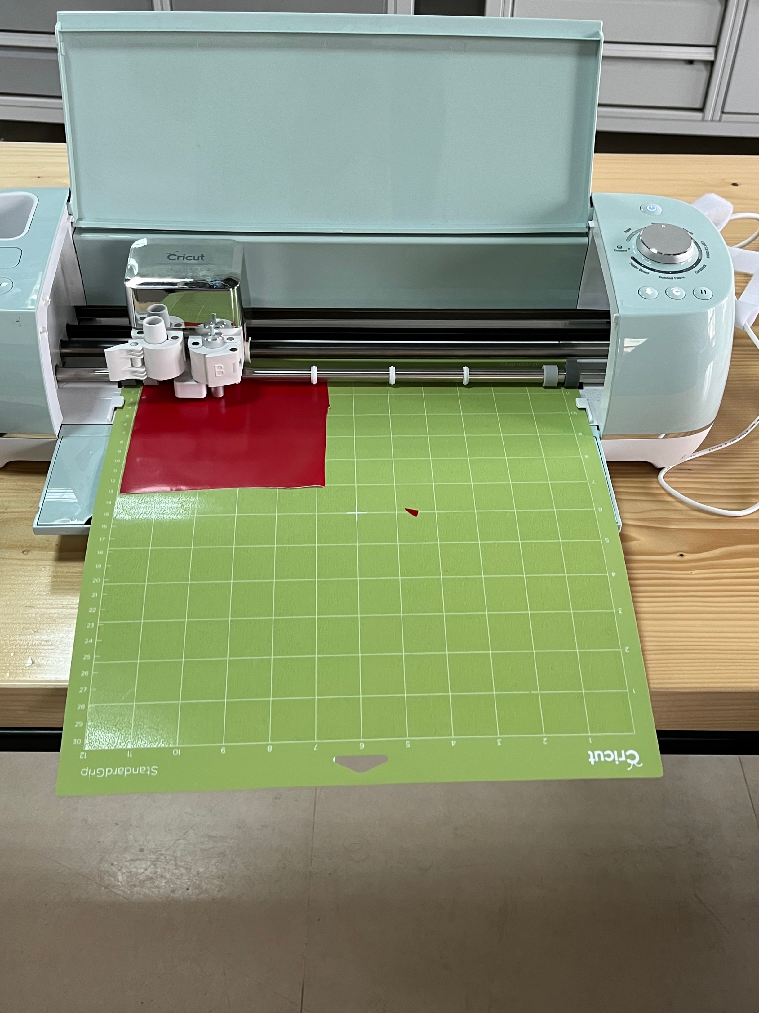
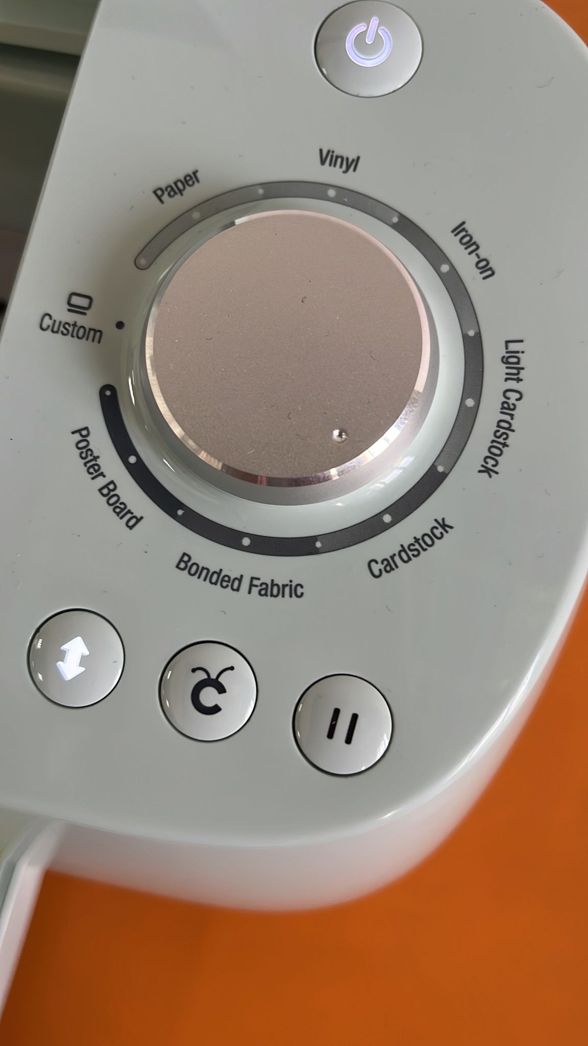
After researching, today we started to learn how to operate the ‘Cricut Explore Air 2’ DIY cutting machine with the help of the supervisors. First, we downloaded the software that is specifically used for the machine. After that, we choose the shape and type of the material of the stickers we wanted to cut and adjusted the machine settings accordingly.
Vinyl cutter - ricut explore air 2 cutter (vinyl cutter) was manually utilized to make 2D designs into stickers that can be used for various purposes. It uses blades with a command coming from a specific software (Cricut design space software) to cut the imported design on the sticking sheet. The vinyl cutter looks as shown below:
The design
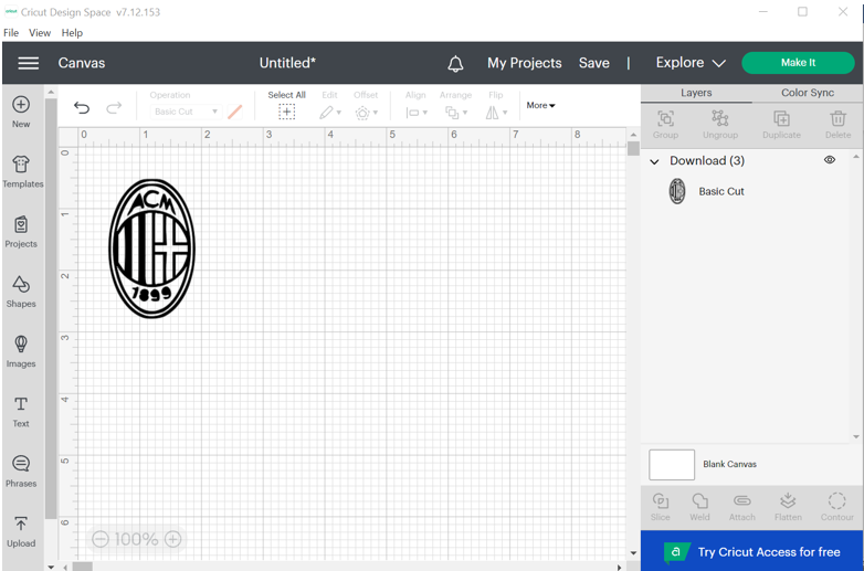 - A simple design was upload and it would be adjusted based on the location of the sticky sheet used:
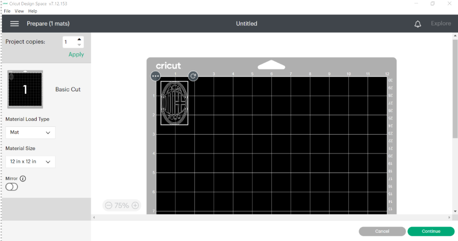 - A sticky sheet is adjusted based on the dimensions of the design with an extra offset to make sure that the cutting procedure succeeds, and it does not go off the edges. Later on this sticker is put into the sheet used in the vinyl cutter:
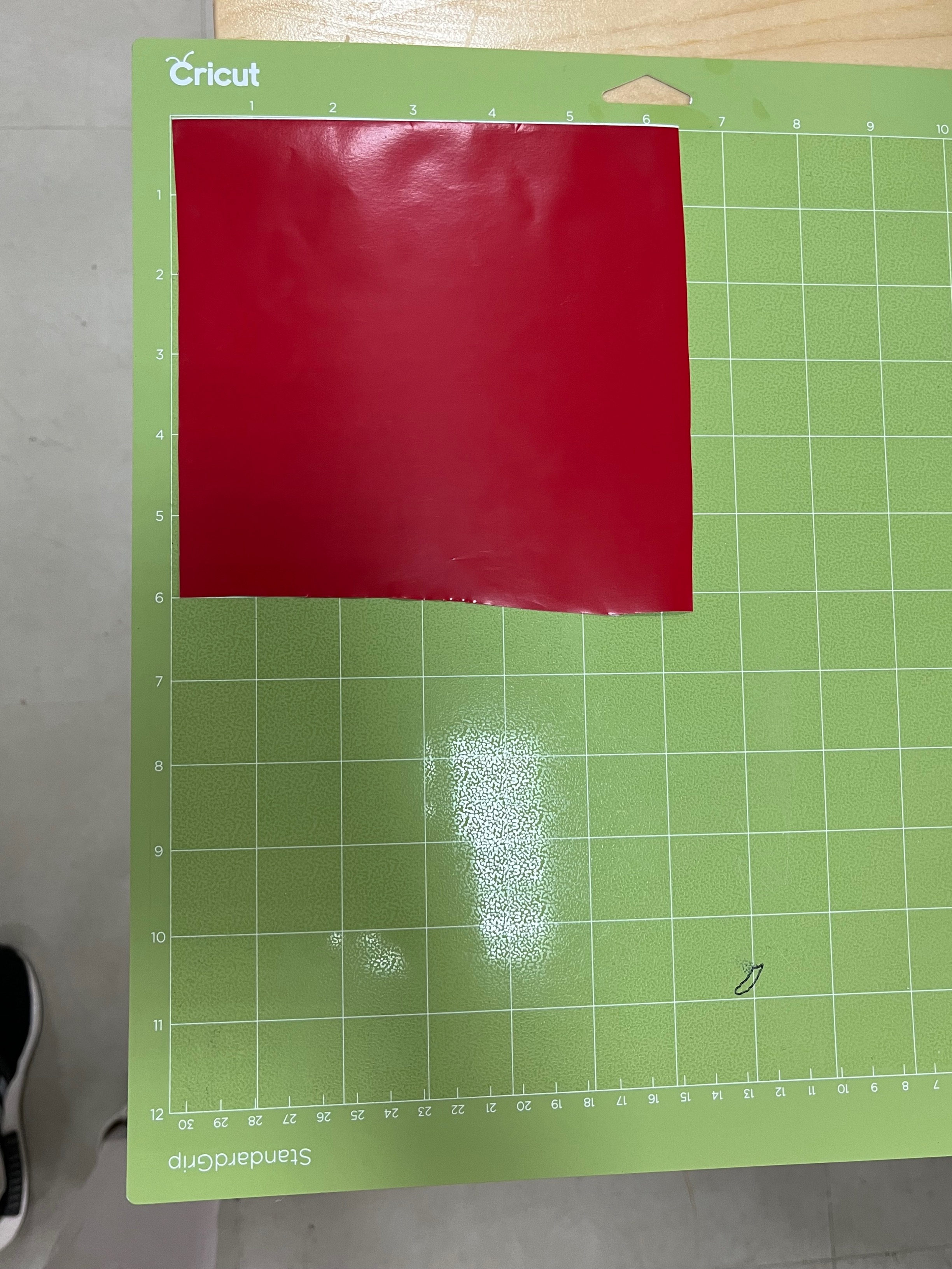 - After that, the sheet is put inside the vinyl cutter to fit it inside the machine to prepare it for cutting:
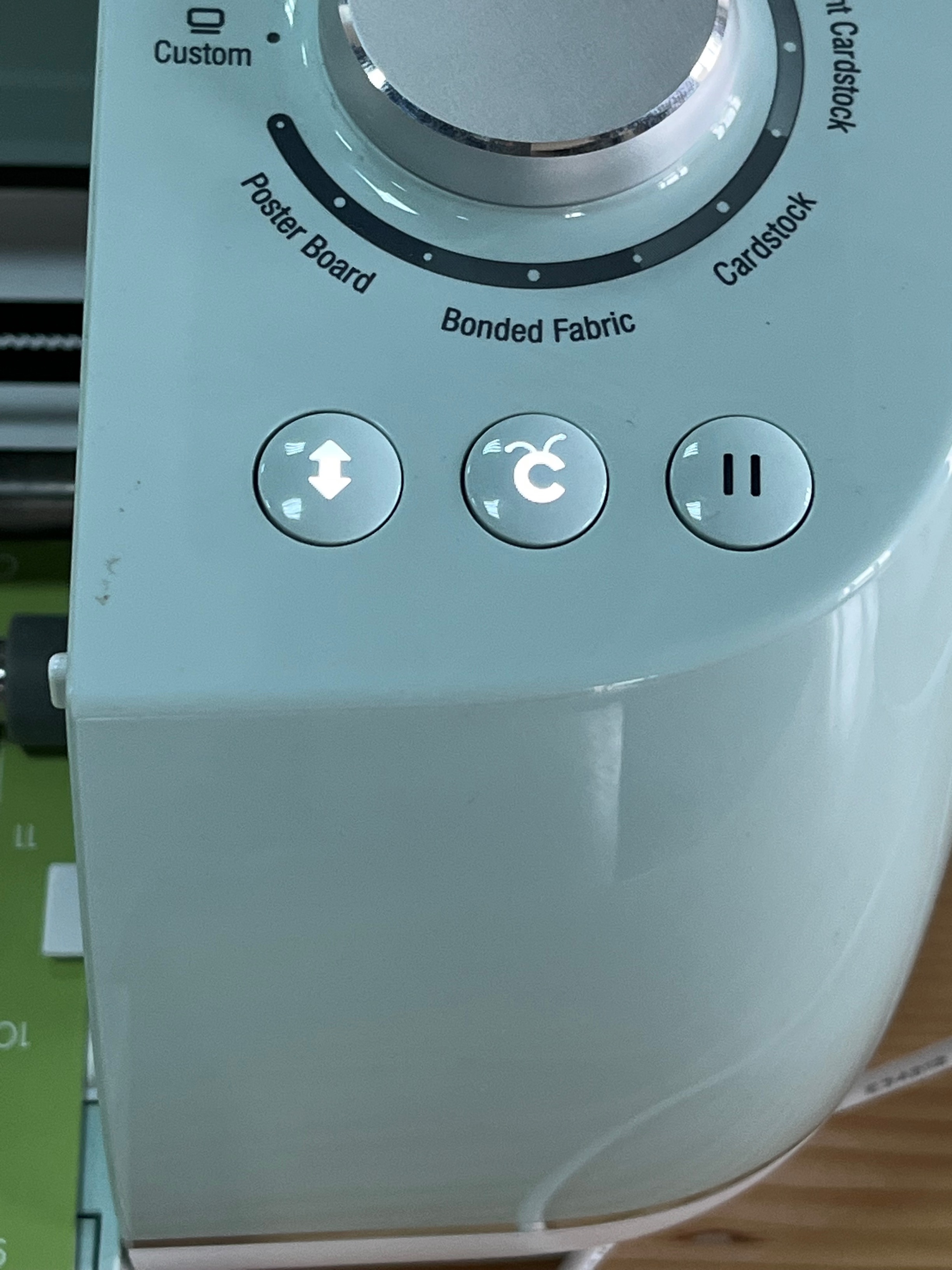
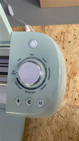
 - Then, this button will flash which would be later pressed to fit the sheet inside the vinyl cutter
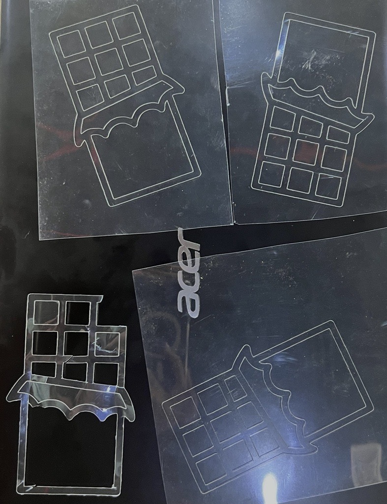
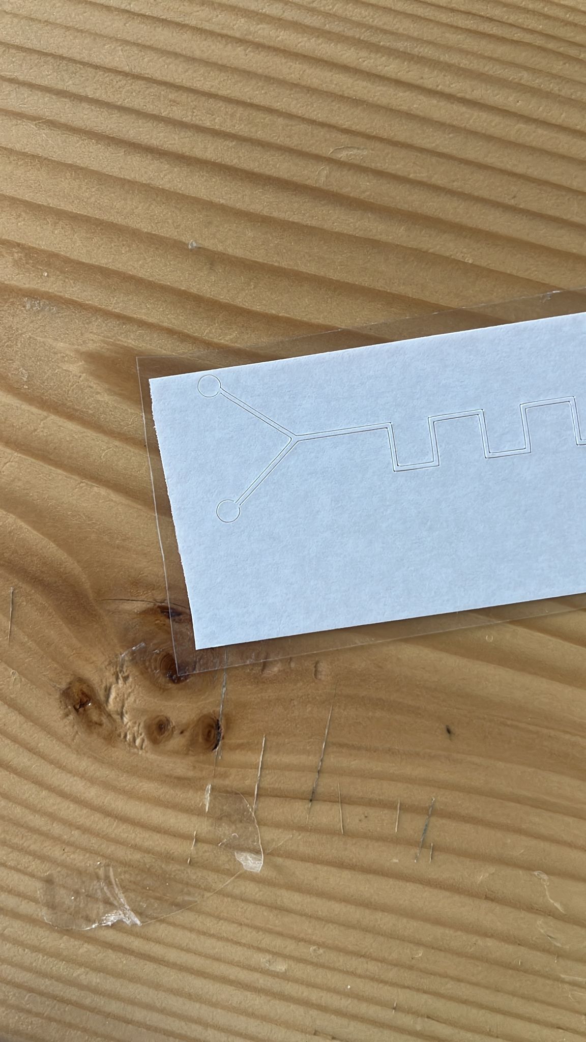
 - This is how the sticker will look after removing the sticky material surrounding the design and after removing the excess material, the design will look like this:
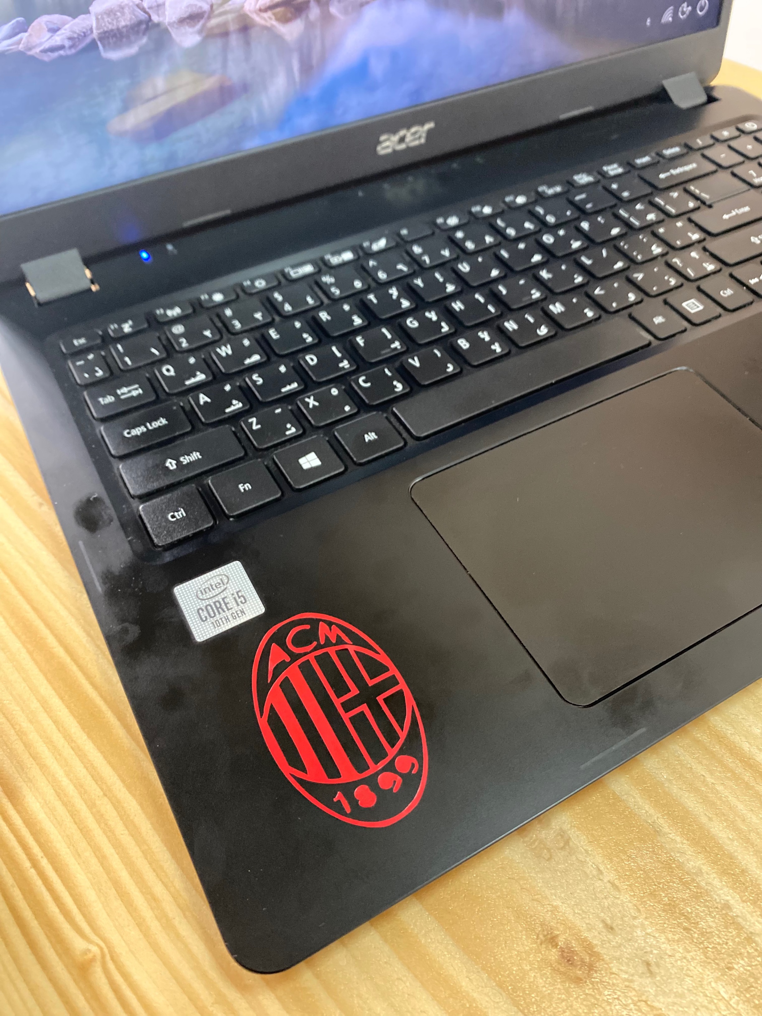
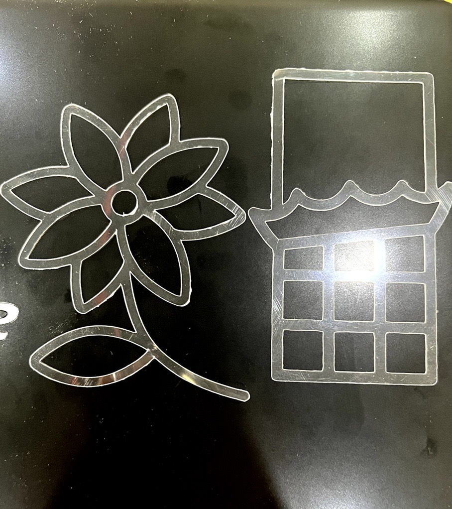
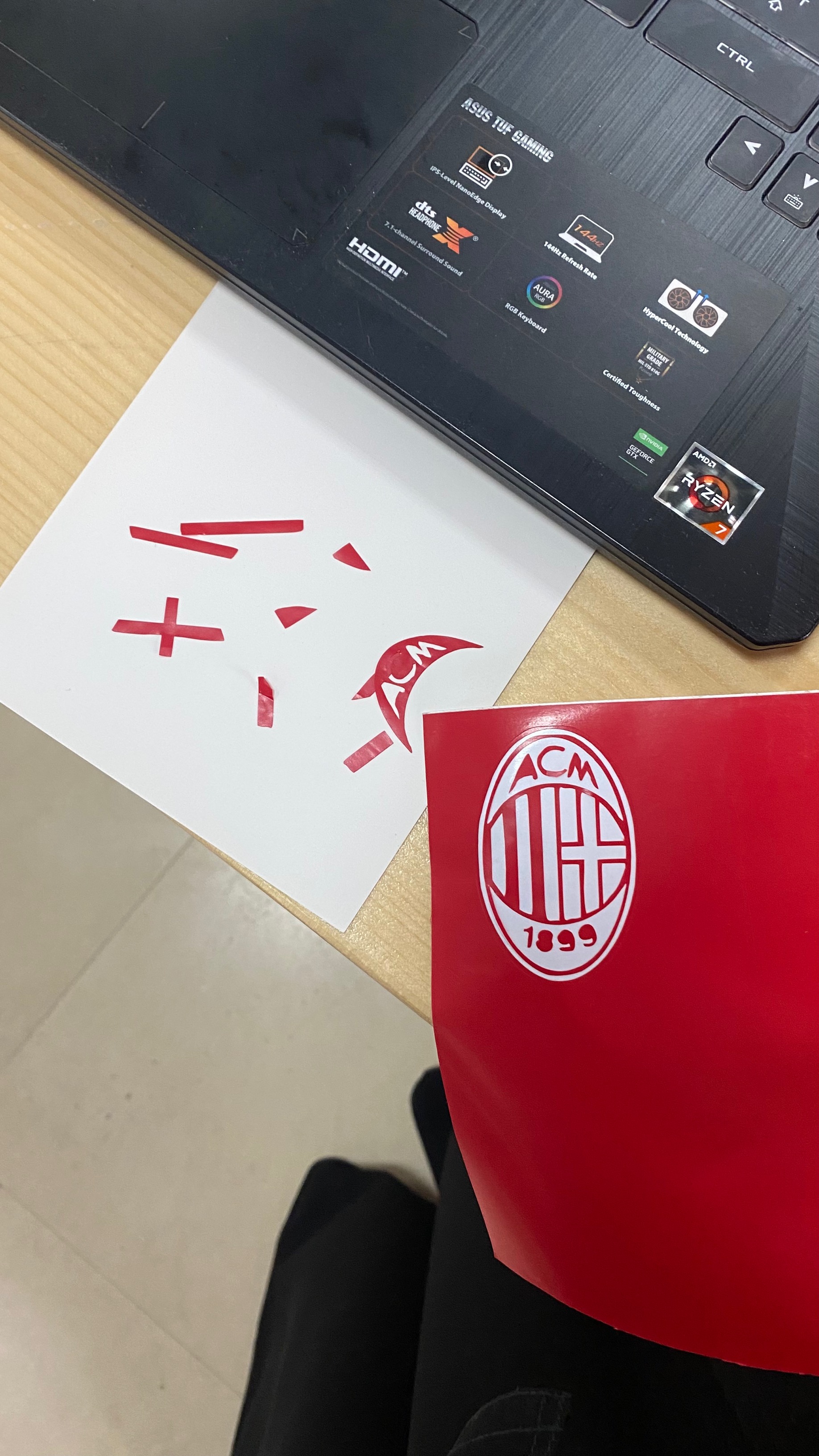 - The final design will look as follows:
Using plastic sheet
After cutting on sticky sheet using the machine, today we tried cutting on plastic type sheets, at the first try we adjusted the vinyl cutter at the (light cardstock) where the power wasn’t enough to cut through the material used as shown in the pictures. Therefore, we kept gradually increasing the power until the ( poster board) power was a success.
- The first Try (light Cardstock )
- The results of the unsuccesful tries
- The final try (Poster board)
- the results of the final try
Designing the microfluidic chip
First, using the 3DUF website we learned how to design the chip. After that, by using the Inkscape program we combined the SVG files and finally imported them in the Cricut program.
3D Testing
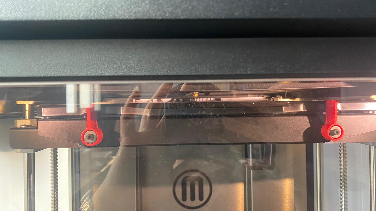
the aim of this testing was to find out the minimum dimentions that we can achieve by using Makerbot 3D printer.
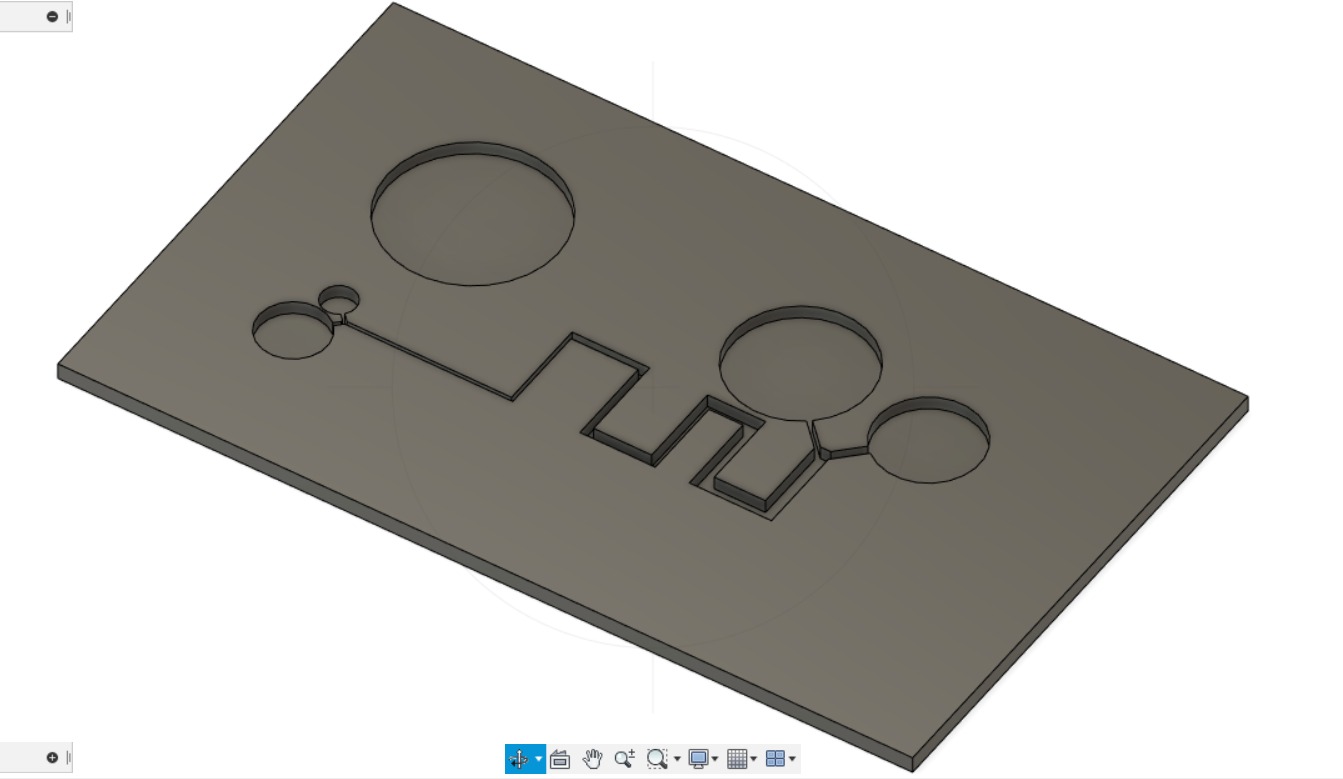
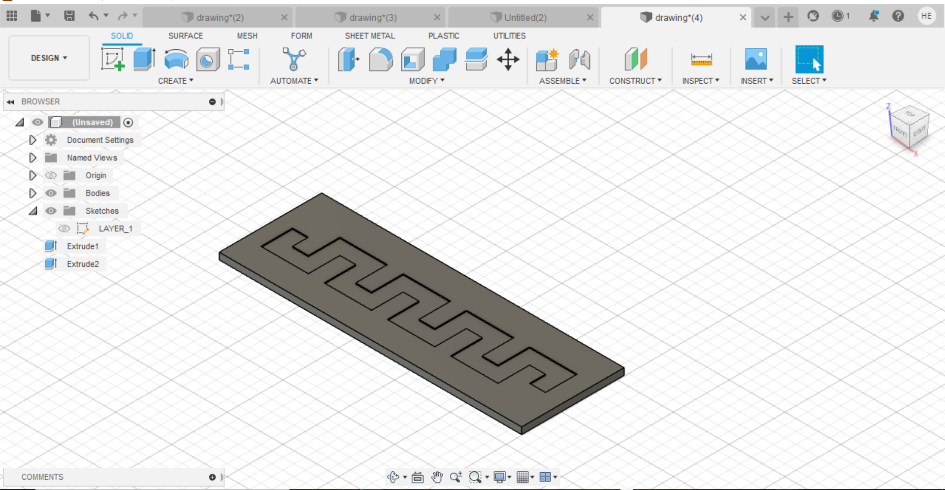
- Step 1: we Started by creating the designs using Fusion 360 and we came up with two designs
- Step 2: We saved the designs as STL files and uploaded them into the makerbot software to do the slicing. After that, the machine started to print the designs
- The result of the printing
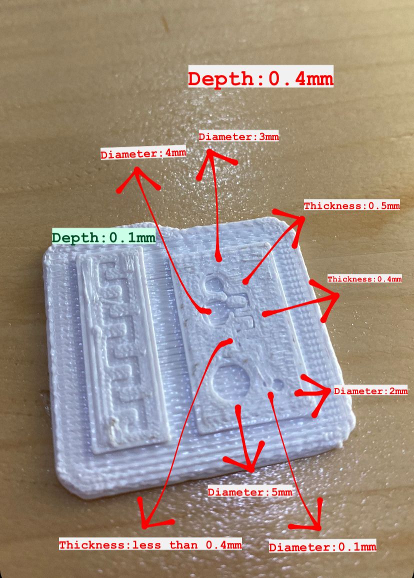
- Step 3: Then, we downloaded the ImageJ software and we plugged in the digital microscope to measure the dimentions of our physical designs. We used a lego as a standard for the scaling to convert the pixels into mm
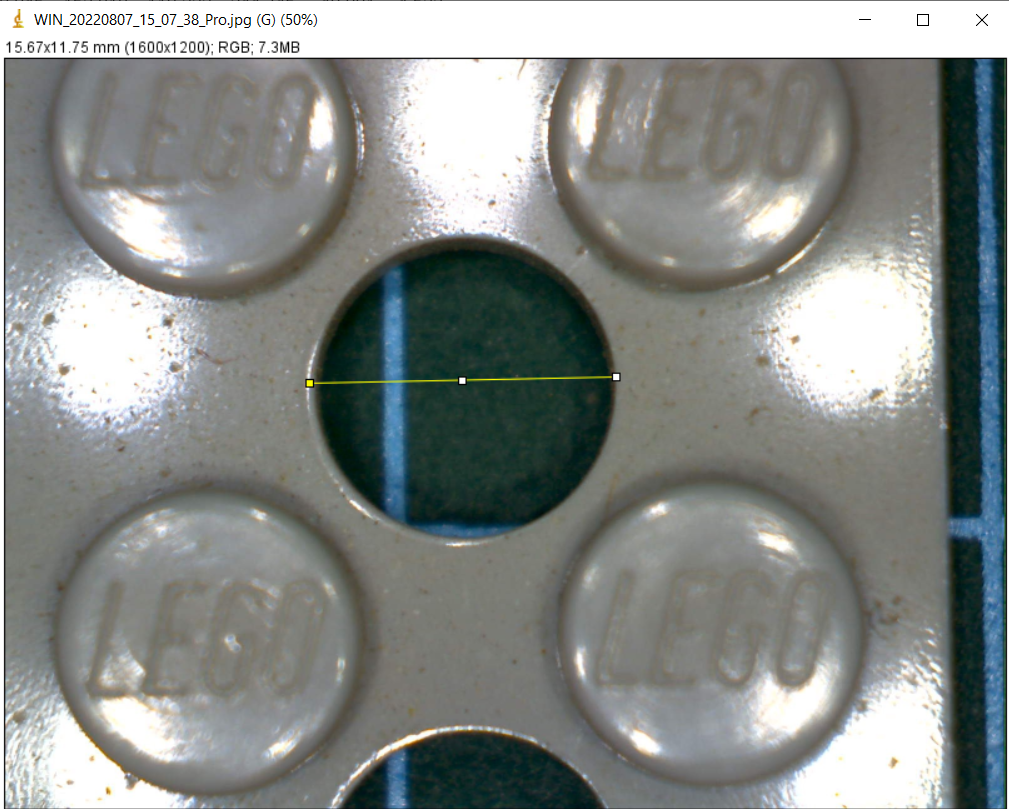
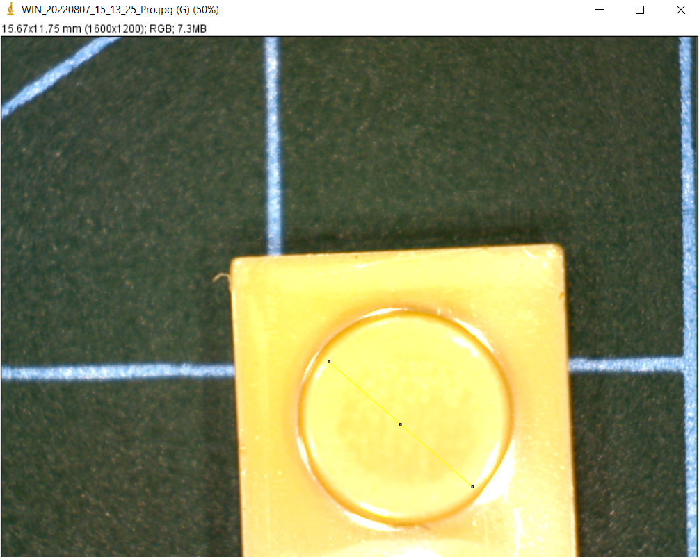
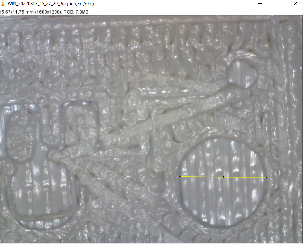
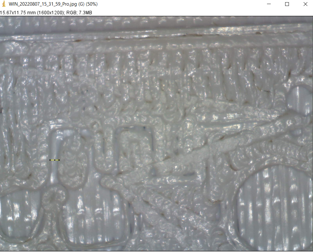
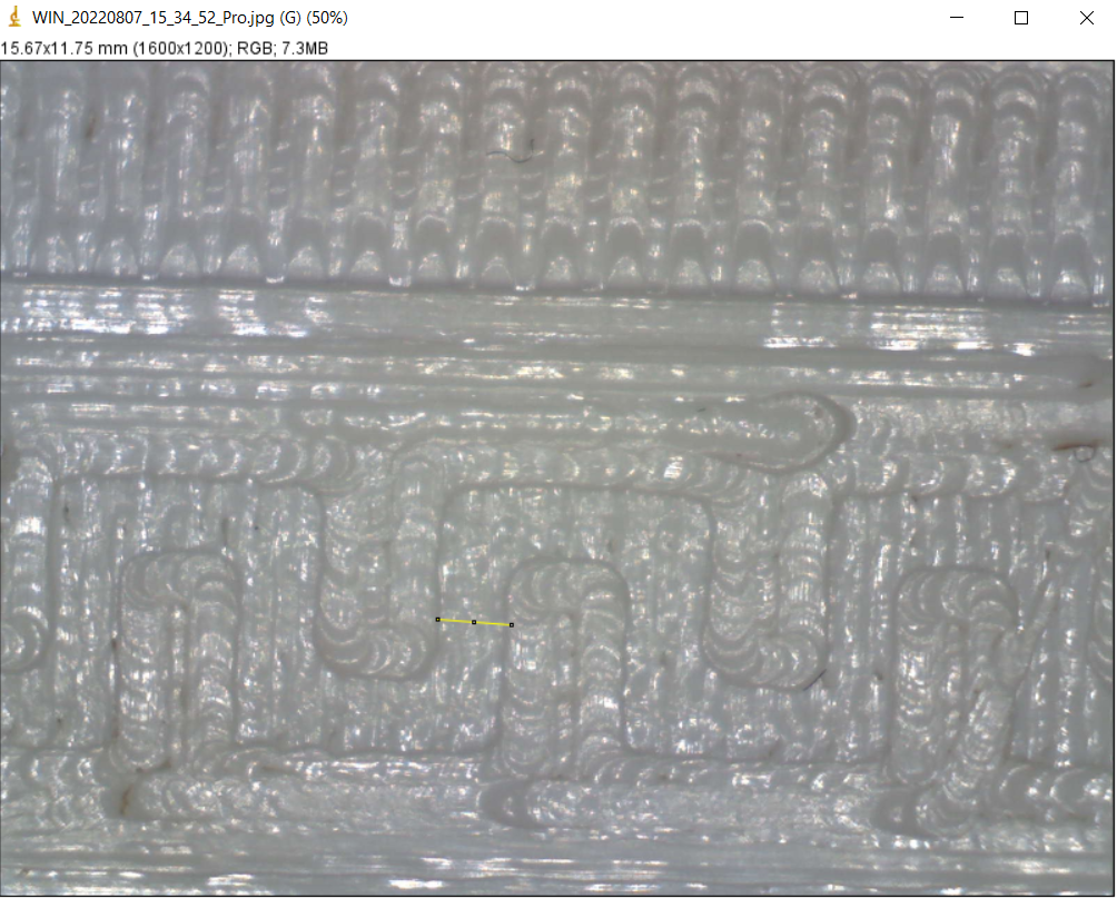
- Step 4: After that, we measured the dimentions for our designs to find out if there is any error during the printing and we found out that the makerbot has a tiny error of 0.05 mm

Microfludic Chip Design:
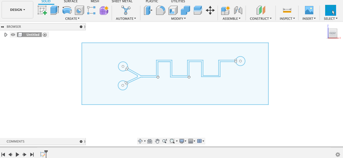
we designed the microfluidic chip using Fusion 360, where the input and output holes are (3mm) in diameter and the width channels is (o.5mm)
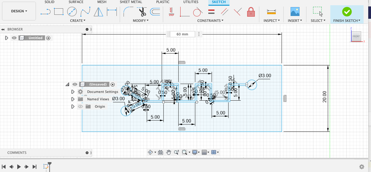
And we also added a square, to make sure the same dimensions are used in the vinyl cutter Cricut design software
Microfludic Chip Fabrication:
Since the main objective of our project is Design and Fabricate an educational kit to explore microfluidics systems and applications using a low cost readily accessible materials and technologies.
The microfluidic device consists of ( two Plastic layer and a double-sided PSA tape) The PSA layer sandwiched between two 50 mm thick plastic protective layers) As we mentioned previously these are the required things that we need in order to fabricate our microfluidic device via Vinyl Cutter:
First of all, we uploaded the design in Cricut Design software. However, before printing the design The double side tape was put (or sticked) into the Plastic layer and we stuck this protective layer into the sheet used in the vinyl cutter:
We tested the power several times and we observed that the suitable power to cut the design out from a double-sided PSA tape is ()
As it is shown when we upload the design in the software, the dimensions of the chip are changing so in order to avoid this issue we will draw a rectangular through the design in order to make sure that the dimensions will not change. Also, we have to press on (attach) to merge the channel with the input and output
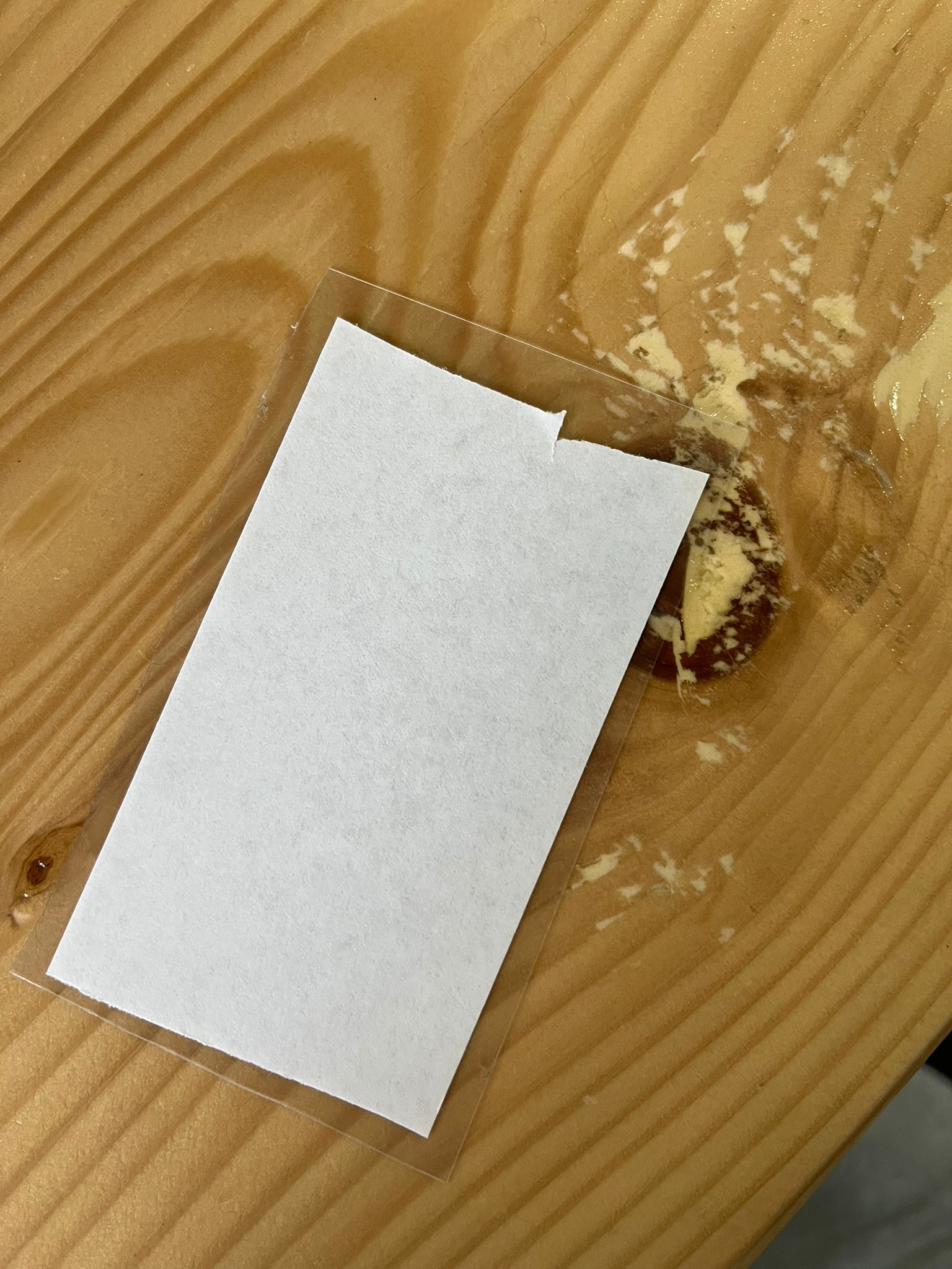
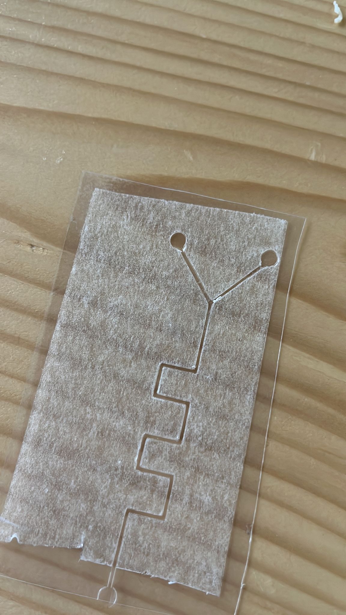
This is what it looks like after cutting:
After that, the cut pattern and its sticky path were carefully removed:
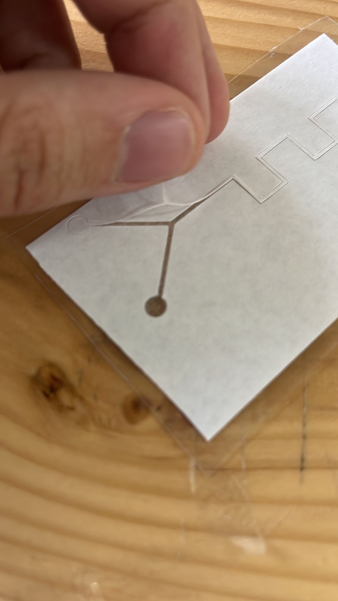
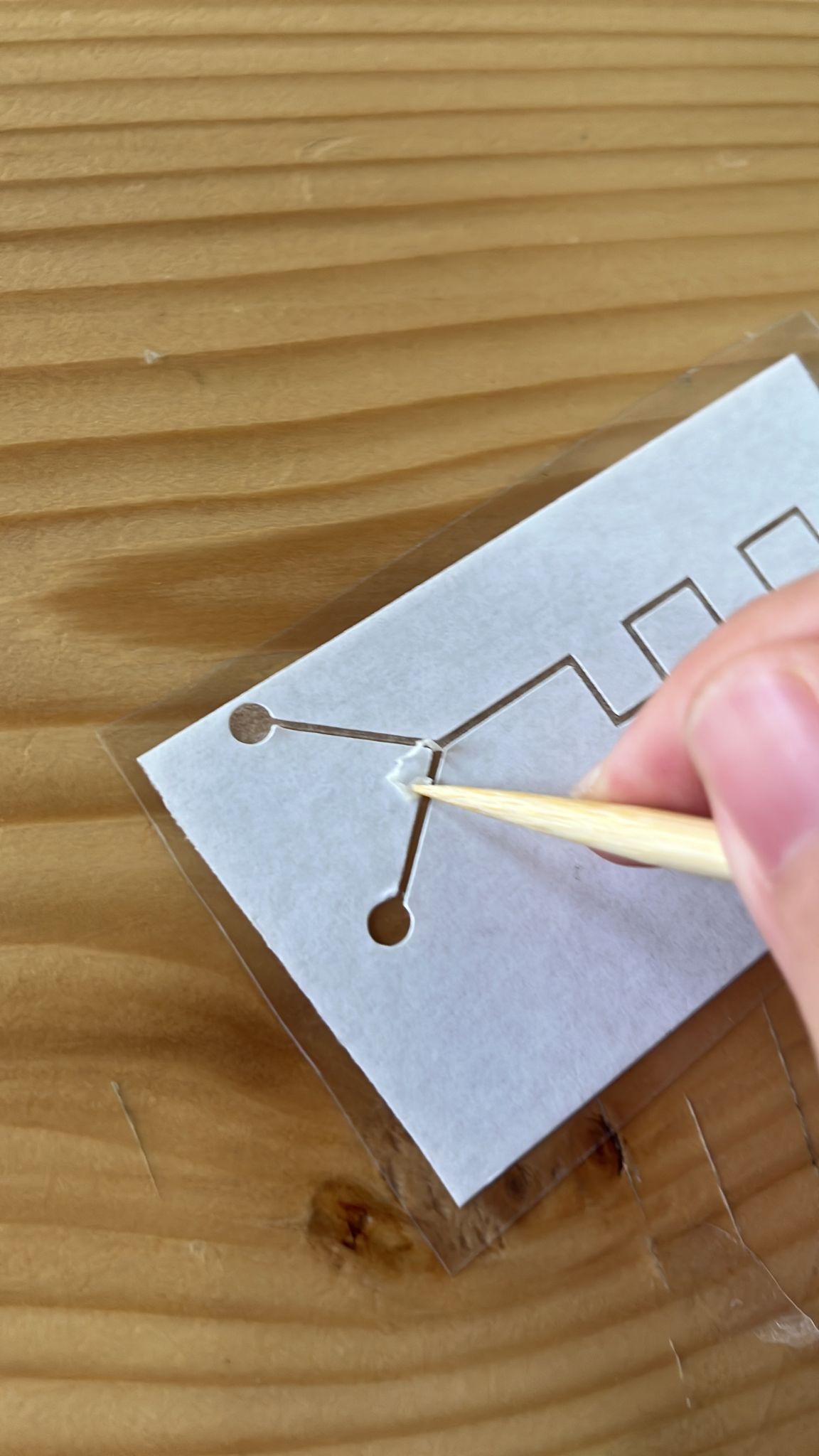
It was difficult to punch the input and output holes using the vinyl cutter because when we tried, it was not matching the design that in the tape so what we did is:
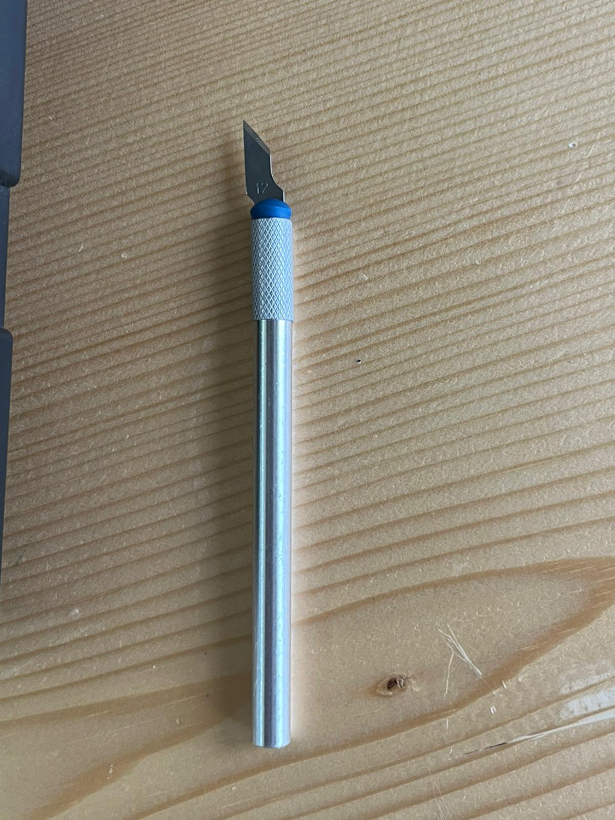
before putting the second protective layer the assembly was flipped in order to make the input and output holes using the tool that is shown below:
Then, the bottom protective layer was pressed onto the next double-sided PSA tape surface and care was taken not to cause any air bubbles or winkles in the double-sided PSA tape
Afterthat, we tested the chip by adding two colors, each color to an input, where both are mixed and the color resulted came at the output.
Microfluidic Chip Test
resources
- what is microfluidics
- general overview
- Low-tech microfluidics
- Low-cost microfluidics: materials and methods
- Basic Microfluidic Concepts
- Low-cost microfluidics: materials and methods