FAB ACADEMY PROJECT : DC 12V Pump
Introduction
A DC 12V Mini Submersible Noiseless Water Pump is a low cost, small size Submersible Pump Motor which can be operated from a 12V power supply he project can be separated into three parts. Firstly, the electronics including the programing and connections. Secondly, design the case of the DC pump and the parts inside it. Finally, assembling the parts.
Electronics
The electronics used in DC pump are the power supply, the Arduino microcontroller, the driver, (DC motor), I2c capacitive touch sensor .
DC Motor and Driver
A DC motor or direct current motor is an electrical machine that transforms electrical energy into mechanical energy by creating a magnetic field that is powered by direct current. When a DC motor is powered, a magnetic field is created in its stator. The field attracts and repels magnets on the rotor; this causes the rotor to rotate. The motor rotates based on the specified speed for the motor. Actually, we don’t call it speed because it doesn’t correlate to a particular number of revolutions per minute (RPM). RPM depends on the motor and the voltage which is unknown. So, to a motor you can set the throttle attribute. The throttle range will be from -1 to 1 however, the motor will rotate in the reserve direction at the negative values. Therefore, the range that were used from 0 to 1. We observed that the motor starts rotating at 0.5 throttle. As it shown below when the setup was at 0.4 throttle the motor does not work probably.
the DC motor looks like:
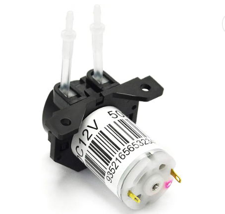
Adafruit Stepper + DC Motor FeatherWing was utilizied as a driver for th DC pump which will supply a power of 12 V for the pump itself by converting the power from power adapter into the dc pump.
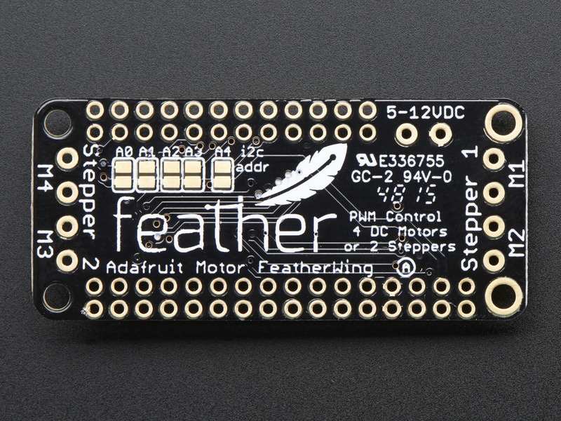
Motor FeatherWing Specs: - 4 full H-Bridges: the TB6612 chipset provides 1.2A per bridge with thermal shutdown protection, internal kickback protection diodes. Can run motors on 4.5VDC to 13.5VDC. - Up to 4 bi-directional DC motors with individual 12-bit speed selection (so, about 0.02% resolution) - Up to 2 stepper motors (unipolar or bipolar) with single coil, double coil, interleaved or micro-stepping. - Motors automatically disabled on power-up - Big 3.5mm terminal block connectors to easily hook up wires (18-26AWG) and power - Polarity protected 2-pin terminal block and jumper to connect external power, for separate logic/motor supplies - Completely stackable design: 5 address-select jumper pads means up to 32 stackable wings: that’s 64 steppers or 128 DC motors! What on earth could you do with that many steppers? I have no idea but if you come up with something send us a photo because that would be a pretty glorious project.
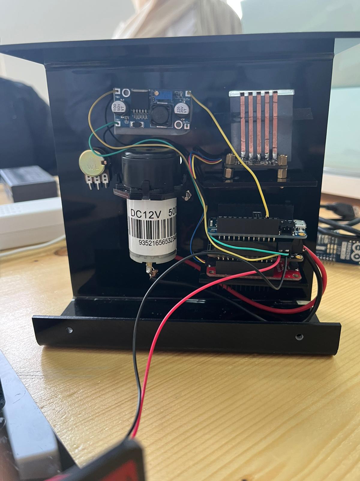
Power Supply
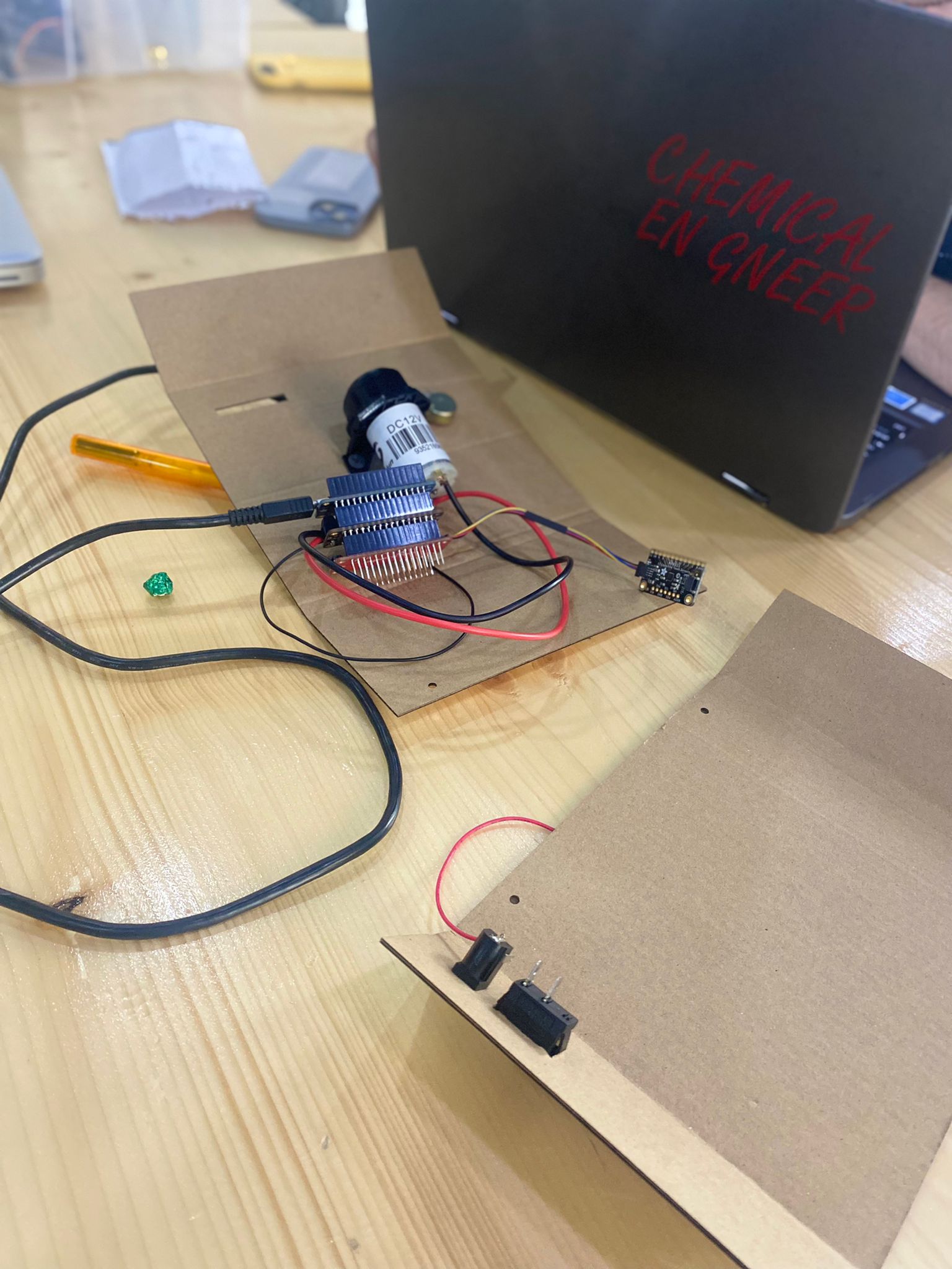
The power supply converts the electrical power attained from the source into the specified voltage for the application. It is the main source of power for the electronic parts. The connections of the wires were connected into Motor FeatherWing chip.
Microcontroller and Circuit_python
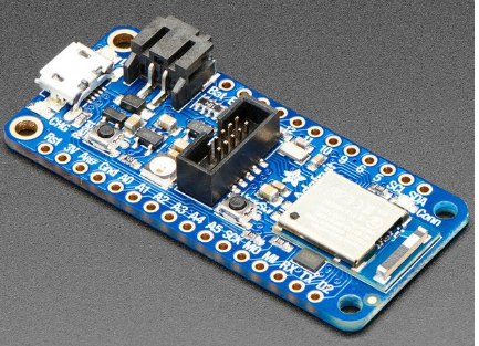
The Arduino microcontroller was utilized as the heart of the electronics of the DC pump by controlling the instrument, where it contains the code program that is used in order to control the DC pump. In addition, Circuit Python was used to write the code . Circuit-Python is a programming language designed to simplify experimenting and learning to code on low-cost microcontroller boards and learning to code on low-cost microcontroller . Circuit-Python is easy to use because all you need is that microcontroller board, a USB cable, and a computer with a USB connection. But that’s only for beginning in order to program code then it will be saved directly in the board even without PC connection. Mu-Editor was downloaded to write the code from this link
microcontroller that was used is Adafruit nRF52840 Feather and it looks like:
convertor
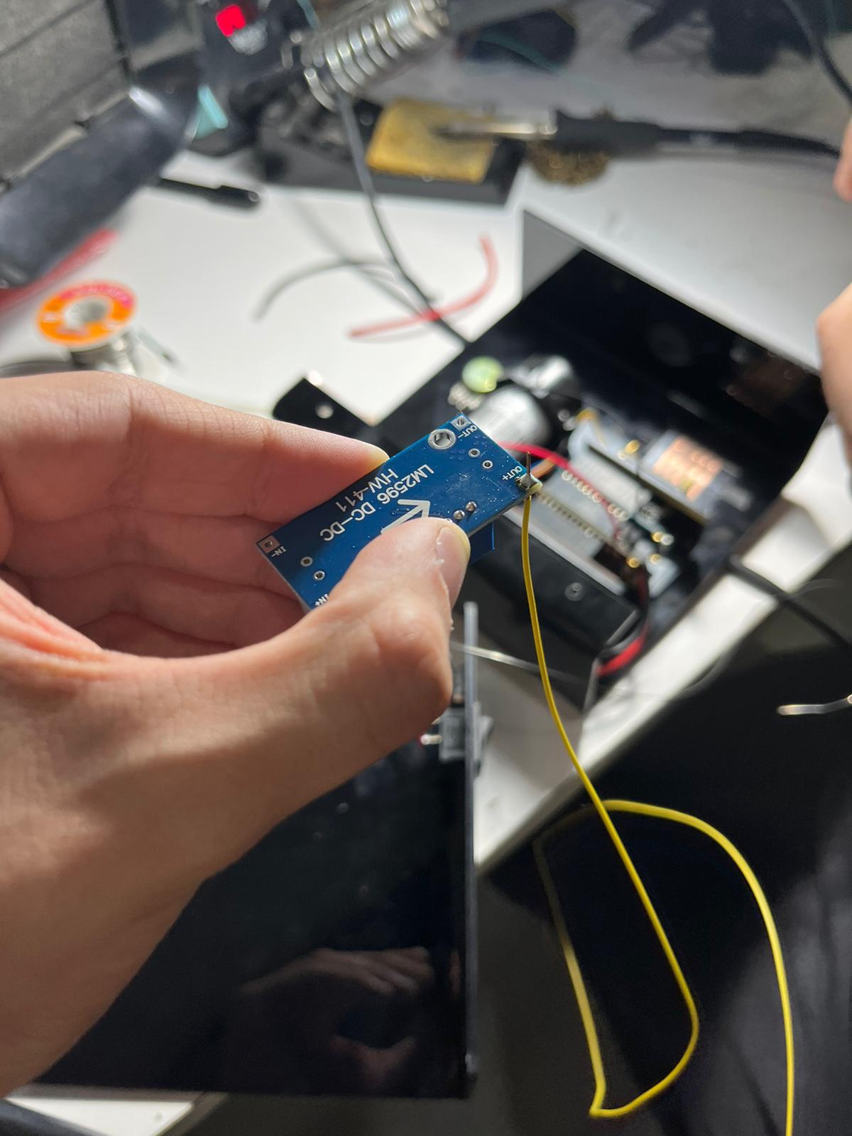
Since we will disconnect the PC from the micro and therefore a power supply source is required to give 5v for microcontroller, so we used the convertor chip called (LM2596 DC-DC Buck Converter Step Down Module). Which will take the power from the Motor FeatherWing chip and convert it into 5v then will connect into microcontroller board. first we measured the voltage using the multimeter device in order to make sure the power gives 5V and if not we have to adjust it until we will get 5 v.

the multimeter:
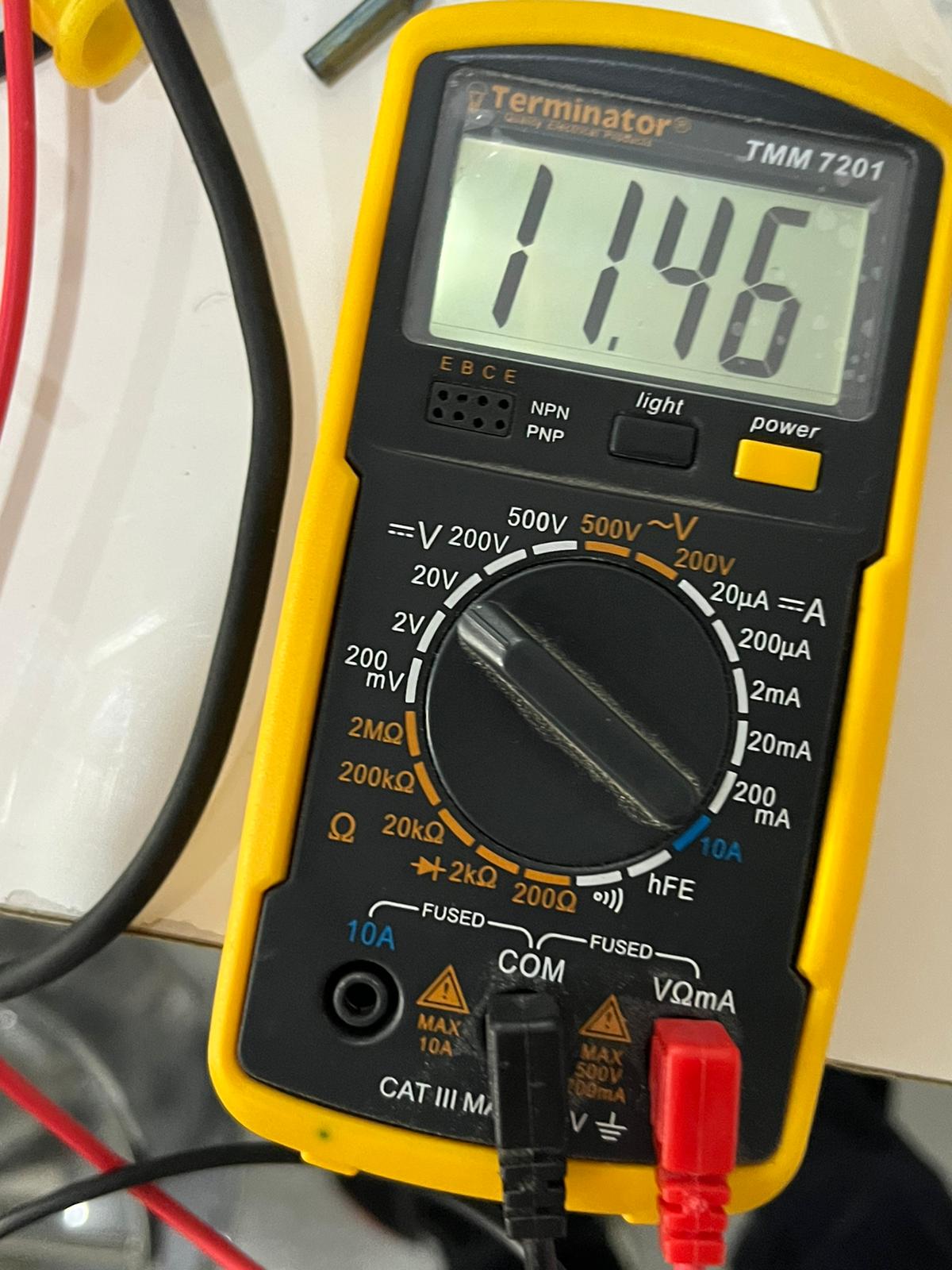
this is the way of how we adjusted in order to get 5v:
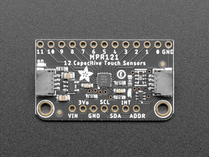
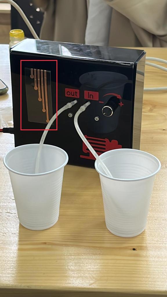
Adafruit MPR121 12-Key Capacitive Touch Sensor
The MPR121 has support for only I2C, which can be implemented with nearly any microcontroller. You can select one of 4 addresses with the ADDR pin, for a total of 48 capacitive touch pads on one I2C 2-wire bus. Using this chip is a lot easier than doing the capacitive sensing with analog inputs: it handles all the filtering for you and can be configured for more/less sensitivity. Know what we did is that we were used only 5 pins and each pin will indicate different flow rate ( i.e different throttle and time) that will be discussed with the code and calibration section
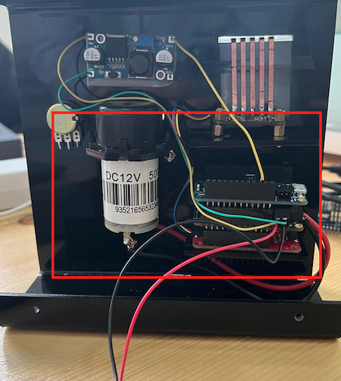
The all boards will be connected to each other in a parallel way, and for the touch capacitive sensor there will be a shield called SparkFun Qwiic Shield where it will connect the i2c chip with others as shown in following:

code and calibration
The code is simple, and It’s easy to use and link the MPR121 sensor CircuitPython and the Adafruit CircuitPython MPR121 module with the Adafruit Stepper + DC Motor FeatherWing. but we have to import some libraries that are used to control DC motor with the Adafruit Stepper + DC Motor FeatherWing. Such as, MotorKit
The code that was used is shown bellow:
# SPDX-FileCopyrightText: 2017 Limor Fried for Adafruit Industries
#
# SPDX-License-Identifier: MIT

"""CircuitPython I2C Device Address Scan"""
# If you run this and it seems to hang, try manually unlocking
# your I2C bus from the REPL with

# from adafruit_ble import BLERadio
# from adafruit_ble.advertising.standard import ProvideServicesAdvertisement
# from adafruit_ble.services.nordic import UARTService
import time
import board
import busio
# ble = BLERadio()
# uart = UARTService()
# advertisement = ProvideServicesAdvertisement(uart)

# ble.start_advertising(advertisement)
# while True:
#    Normally other work would be done here after connecting.
#   pass

# To use default I2C bus (most boards)
i2c = board.I2C()
import adafruit_mpr121
from adafruit_motorkit import MotorKit
# To create I2C bus on specific pins
#i2c = busio.I2C(board.SCL, board.SDA)  # QT Py RP2040 STEMMA connector

mpr121 = adafruit_mpr121.MPR121(i2c, 0x5A)
kit = MotorKit()
touched = mpr121.touched_pins
# while not i2c.try_lock():
#    pass

# try:
while True:
    # print(i2c.scan())
    if mpr121[0].value:
        print("Pin 0   10 Second")
        kit.motor1.throttle = 1
        time.sleep(10)
        kit.motor1.throttle = 0
    time.sleep(0.2)

    if mpr121[2].value:
        print("Pin 2   0.5 Second")
        kit.motor1.throttle = 1
        time.sleep(2
        kit.motor1.throttle = 0

    time.sleep(0.2)

    if mpr121[4].value:
        print("Pin 4    1.0 Second")
        kit.motor1.throttle = 0.7
        time.sleep(10)
        kit.motor1.throttle = 0
    time.sleep(0.2)

    if mpr121[6].value:
        print("Pin 6    10 Second")
        kit.motor1.throttle = 0.7
        time.sleep(2)
        kit.motor1.throttle = 0
    time.sleep(0.2)

    if mpr121[8].value:
    time.sleep(0.2)

        print("Pin 8  10.0 Second")
        kit.motor1.throttle = 0.5
        time.sleep(10)
        kit.motor1.throttle = 0
    time.sleep(0.2)
# finally:  # unlock the i2c bus when ctrl-c'ing out of the loop
#    i2c.unlock()
from the code it can shown that for each pin there are specified throttle and time where the pump will rotate and take the water at these specifications We measured the output of the fluid using syringe and then we divided the volume of the fluid by the time in order to get the flow rate then we know at these specifications what is the flow rate. So we went back for the code and adjusted it based on the flowrate for example I know that when I have throttle equal to 1 and time is 10s we will get 1 ml/s so I defined these specification at pin 0 so when will touch the sensor at pin zero will know that will get 1 ml/s and so on.
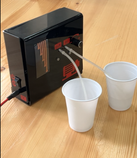
these are some videos of testing the pump:
- 10 seconds and throttle 1 setting
- 10 seconds and throttle 0.5 setting
- 10 seconds and throttle 0.4 setting
Designing the case of the pump
We designed two pieces for the case, one of them was for the front and the depth. While, the other one was to cover the back and the sides. The whole design was created as 2D and by using Fusion 360 software.
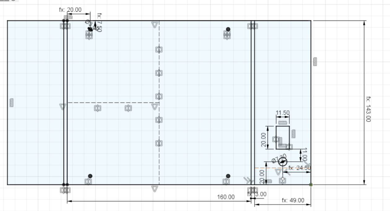
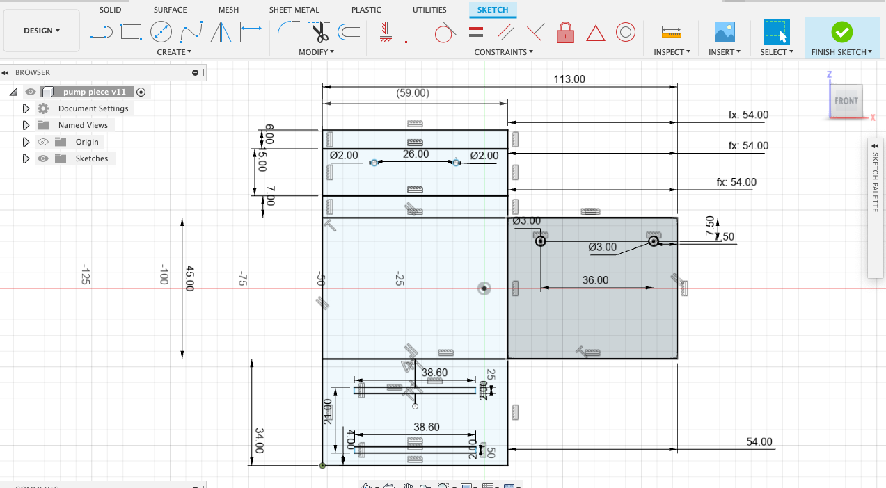
- First, we started by drawing a rectangle for the front piece with a length of 271 mm, width of 160 mm and 52 mm as a depth.
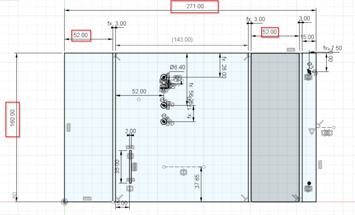
- Then we added lines with 3 mm to specify the place that will get fold while using the heat bending machine.
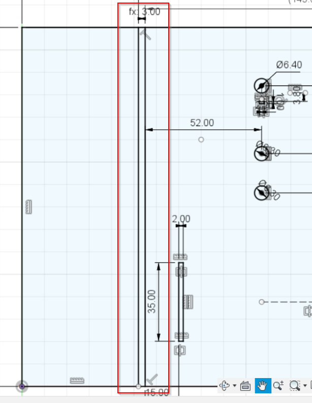
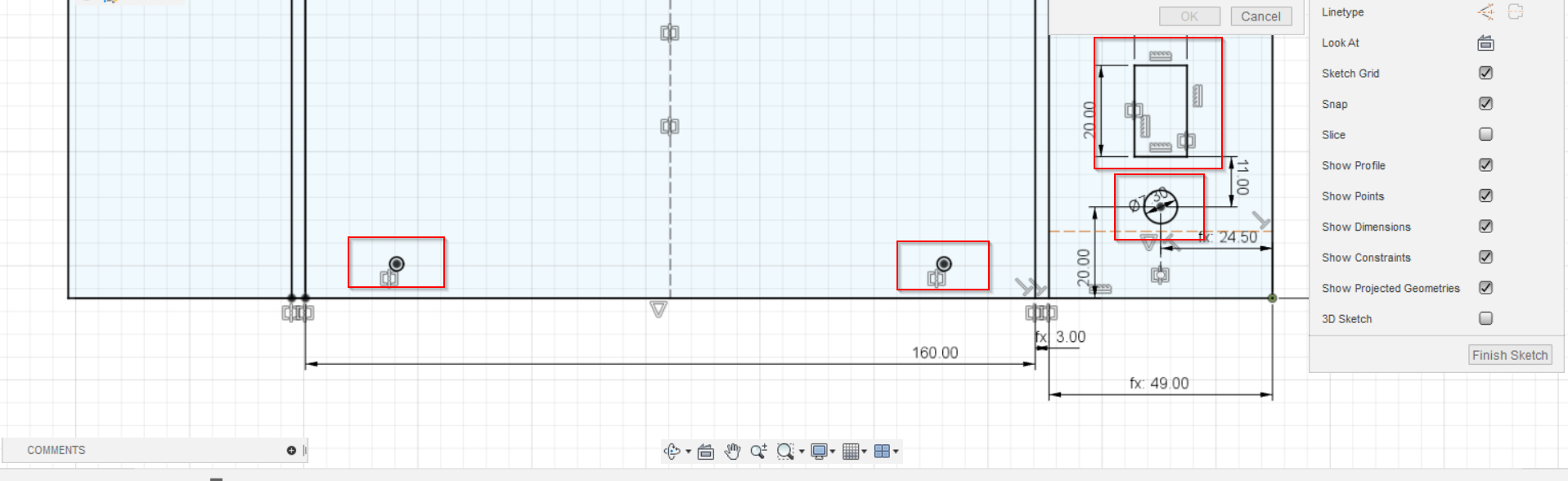
- Next, we used the calliper to take all the measurements like the holes for the screws, input & output, the touching sensors aperture and etc.
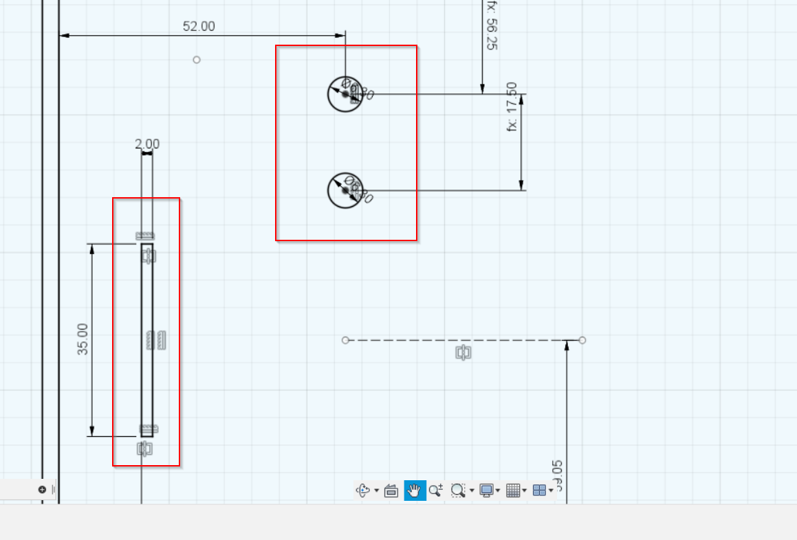
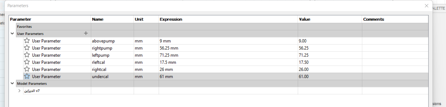
Hint: To make our life easier, we used the parameters to specify the dimentions of everything in the design.
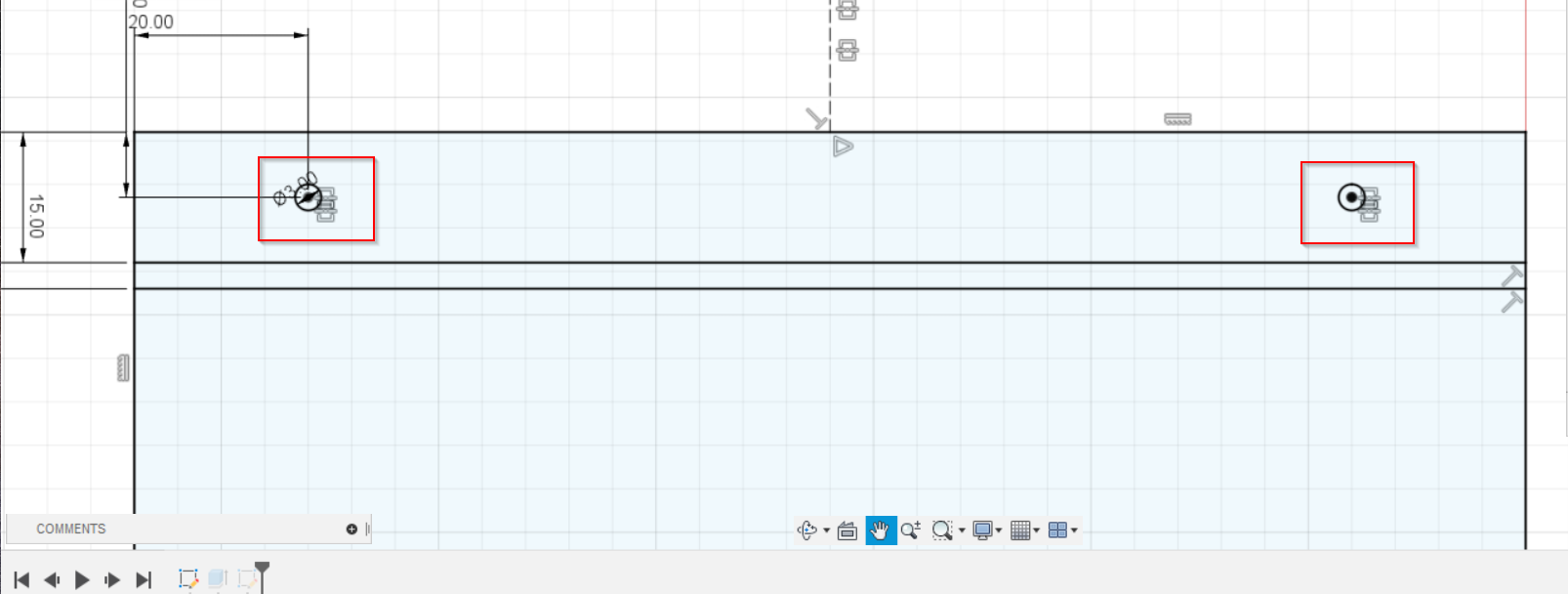
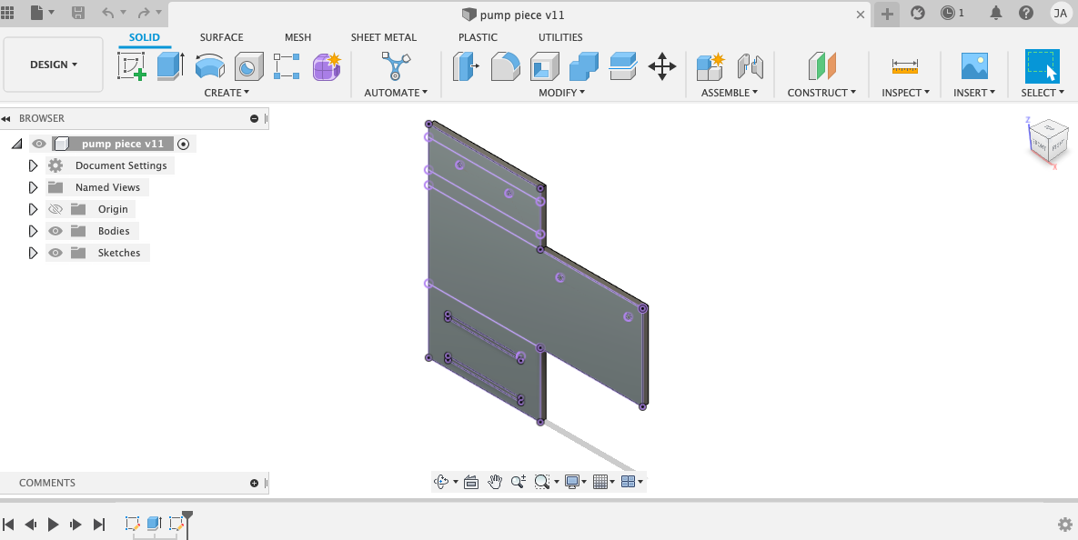
- After that, we designed the second piece which is covering the back and the sides. So, again we started with drawing the rectangle with the same dimentions of the first piece but we substracted 6 mm from the length and width due to the thickness of the material that would be used in our case design which is acrylic material (3mm).
- Then, we added the same holes as we had on the first piece for the screws on the bottom to be able to remove the piece whenever we want to fix something inside the case. Also, we created a hole and aperture on the side for the power source and the ON/OFF switch.
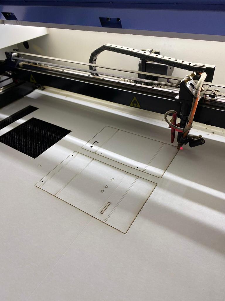
- After being done from designing the case, we saved the file as DXF file and we sent it to the main PC that has the software that is connected to the laser cutting machine. Then, we selected the required speed and power for the material that had been used for the cutting proccess which was the cardboard first for testing our dimentions and then the acrylic for the final result.
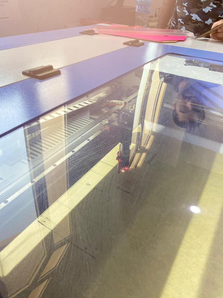
Original file
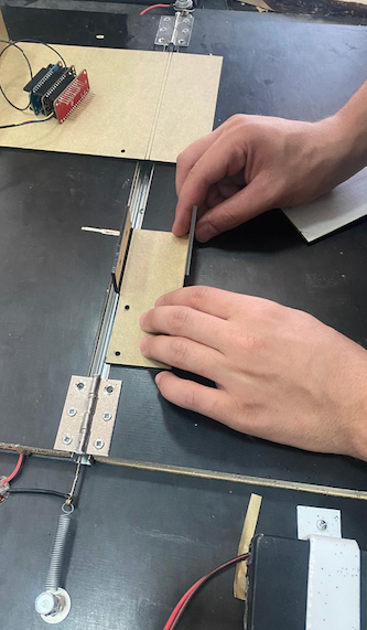
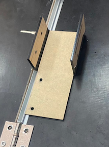
Designing the the Pump stand
- We measured the space between the input and output(where the screws goes) on the piece attached to the pump itself and estimated the lenght of the piece.
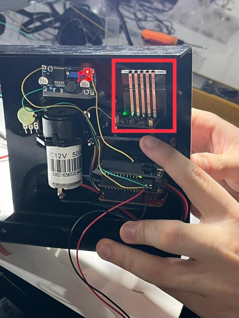
- for the chips, we measured the lenght and cut triangular shape holes for the pins soldered to the chip, which will help holding them (acts like a shelf stand).
-
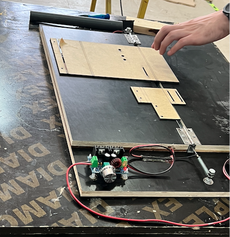
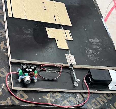
after we did cut the piece using the laser cutter
Bending
- To bend the edges of the case we used the bending tool which it does work by providing heat to the matel piece in the middle and it can bend the material by 3mm at any angle
- after the material gets warm we bend it
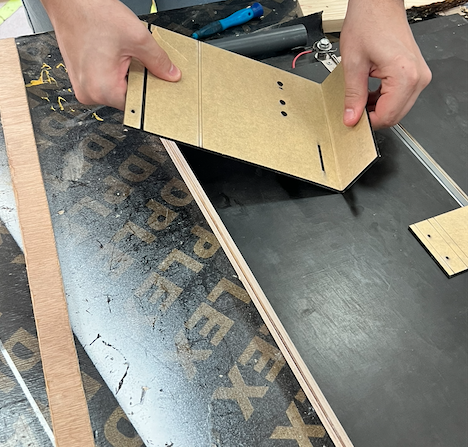
- Finally, we combined the pieces and put them together
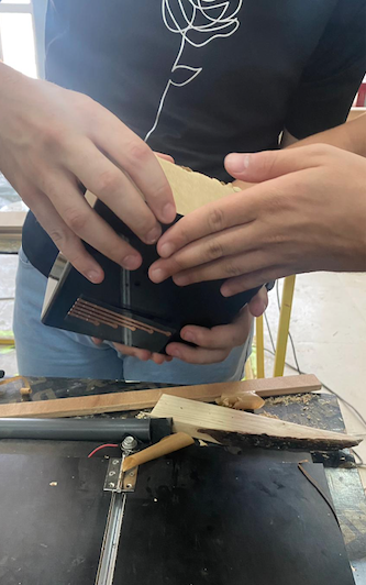
Note: for the bending we must pay attention to the part being bend therefore we don’t break it while bending
Designing the touching sensors
The touching sensors were made up by using the Fusion 360 software and the Vinyl Cutter machine.
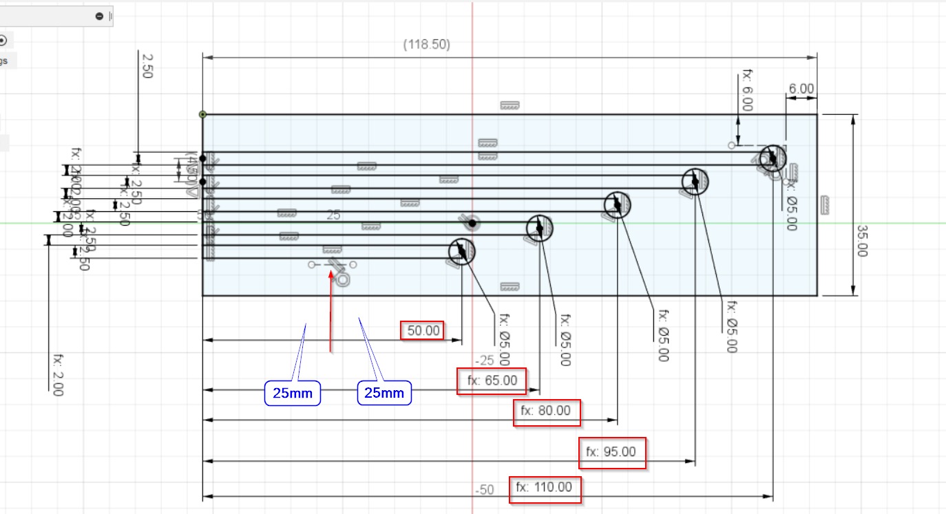
- First, we started by sketching the base which is a plastic with a length of 118.5 mm and width of 35 mm.
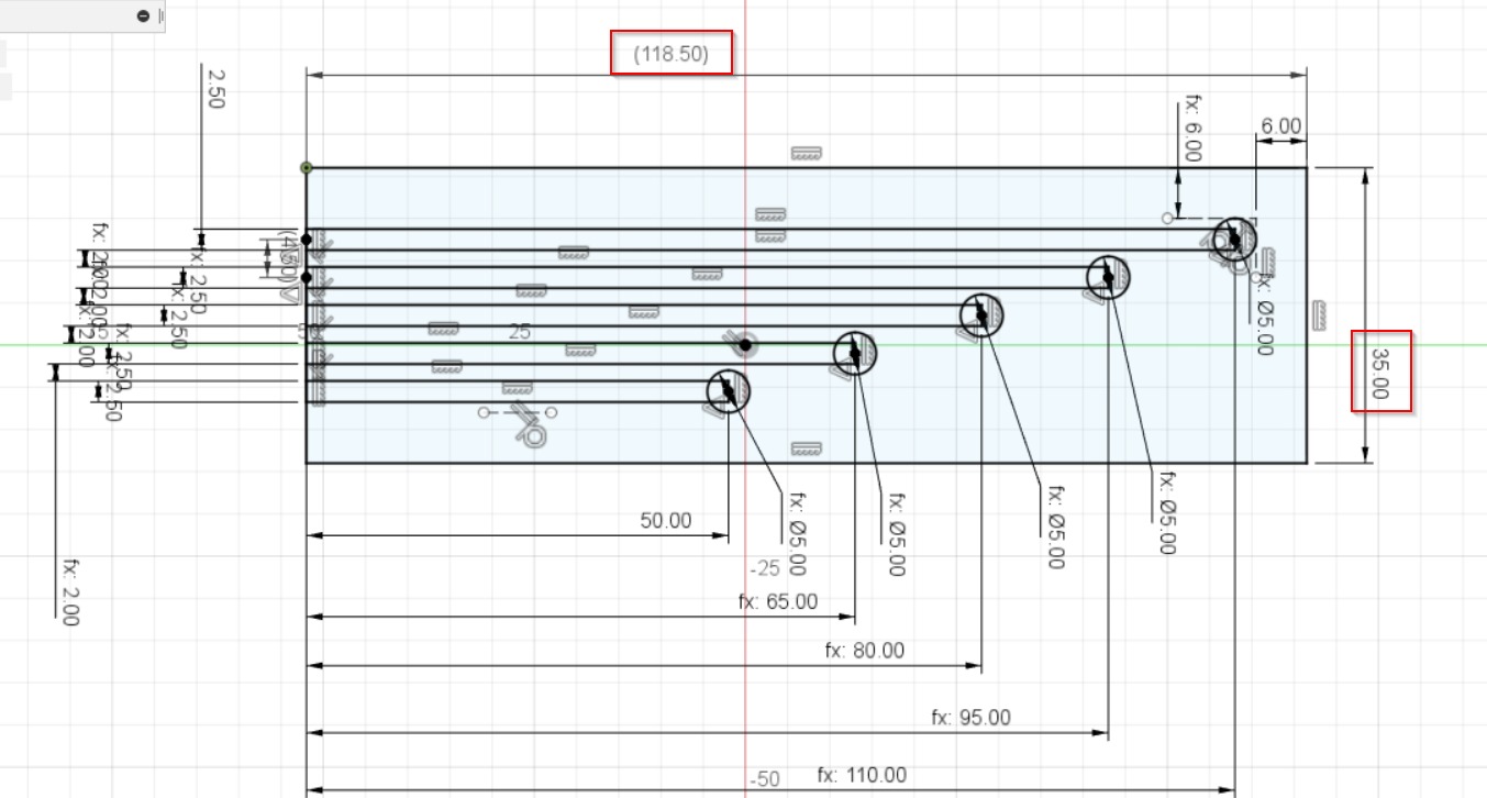
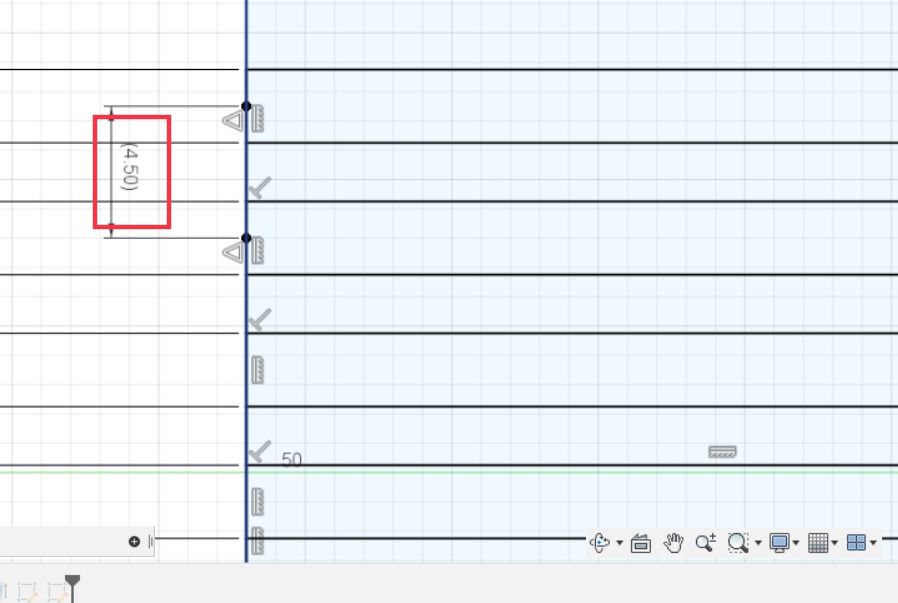
- Then, we measured the distance from the pins that are inside the case to the aperture and we found that it was 25 mm. So, we skipped 25 mm on the design before adding the 5 touching sensors with different length for each of them. The first pin had 50 mm length which is 25 mm the length of the skip and the other 25 mm which is the length of the touching sensor itselt. And then for each pin, we added up 15 mm on the previous length. Furthermore, the distance between the middle of each pin was 4.5 mm.
- After that, we saved the file as DXF file and uploaded it on the cricut software to start cutting the design. We started by cutting the base first which is the plastic by applying the mixmum power (Poster Board).
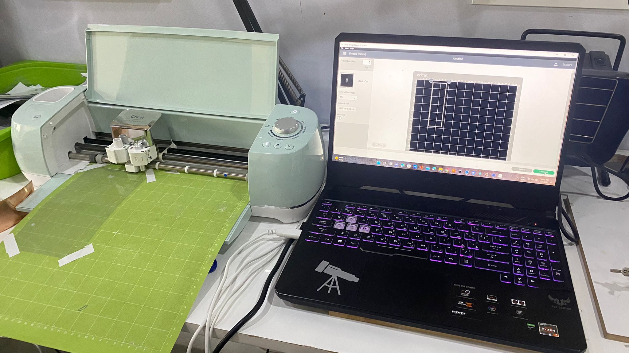
- Next, we sticked the copper on the plastic to let the cricut machine to cut the touching sensors on the copper only. And when the machine was done from the cutting process, we removed the extra copper material around the touching sensors. Finally, we folded it and placed it on it’s position using the aperture that was already made for it.
Hint: Why we used the copper for the touching sensors ? because the copper is a conductive material.
Original file
The final result
After being done from all the designing steps, we added some stickers to the case design using the vinyl cutter in order to show all the details and finish it off.
Problems
-
1- The case for the pump was looking great but there was an issue that it didn’t fit perfectly on the sides due to some errors on the dimentions while we were designing it.
-
2- The final result for the touching sensors were good but we faced a problem regarding touching them because they were too close to each other so it was little bit difficult to avoid touching the other pins at the same time. We recommend to increase the distance between them to be more comfortable while touching them.
-
3- for designing the small piece inside the pump case, we didn’t estimate the lenght correctly so we had to redsign it again.