COMPUTER AIDED DESIGN
The aim of this week was to experiment with different digital drawing and modeling softwares and creating 2D and 3D designs. To fulfil the learning outcomes I used the following softwares:
1. Pixilart for Rastor Drawing
2. Fusion 360 for Vector Drawing
3. Tinkercad for 3D Modeling
4. SolidWorks for 3D Modeling
RASTOR GRAPHICS
Raster images are made of pixels, or tiny dots that use color and tone to produce the image. Pixels appear like little squares on graph paper when the image is zoomed in or enlarged. These images are created by digital cameras, by scanning images into a computer or with raster-based software. Each image can only contain a fixed number of pixels; the amount of pixels determines the quality of the image.
Raster images are best for digital photos and print materials. If a project requires complex color blends, raster is the preferred format.
MY WORK ON PIXILART APP - HEART SHAPED CAR
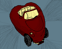
The steps for I performed on pixilart app to draw this are as follows:
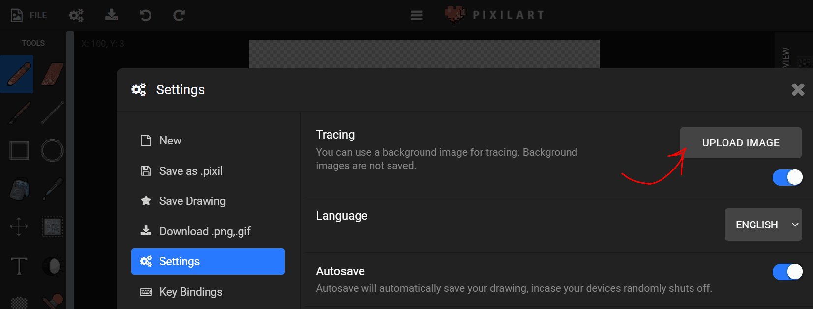
1- I wanted to trace this original car image so I imported it on pixilart by going to settings which opened a control panel.
2- In settings panel, the first heading is called Tracing under which is an Upload Image button which when clicked, opens the computer gallery from where I selected the car image.
3- I selected the Line tool from the tools panel on the side side of the window.
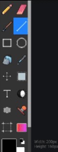
4- To trace, I simple kept drawing lines of small lengths to trace the outline of the car.
5- After finishing the outline of the car, I selected the Bucket icon on the tools panel on left.
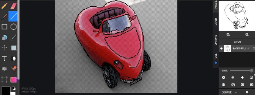
6- On the right is the tools option panel, the last option is called Tools, when selected the first icon is the gallery containing downloadable color palletes.


7- After filling the colors in my drawing, I decided to add some shading, which I did using the Lighten/Darken Tool in the tools panel on left.
8- Lastly I created a new layer, moved it below the current layer and filled it with the desired background color using the Bucket tool.
REFLECTING ON PIXILART APP
I found pixilart app a few months ago while I was working on a pixel game design and since I enjoyed it alot the first time- I decided to do a rastor graphic on it as well in order to explore more of its features. It has a very well structured and simple interface and it also does not require making any account to draw or installation which makes it even more convenient. I also really love the color palletes it has in store created by different users as well as paint patterns such as bricks and much more which I feel is very time saving. The new thing I did this time was upload my pixel art on the app and while uploading they showed different slides of my art printed on various products like cups, shirts etc which I think was really great.
VECTOR GRAPHICS
Vector graphics are also known as scalable vector graphics (SVG). These graphics consist of anchored dots and connected by lines and curves.Because these graphics are not based on pixels, they are known as resolution independent, which makes them infinitely scalable. Their lines are sharp, without any loss in quality or detail, no matter what their size. These graphics are also device-independent, which means their quality doesn't depend on the number of dots available on a printer or the number of pixels on a screen.
A vector graphic's small file size and scalability makes it uniquely suitable for use in digital printing from business cards to billboards. They're also used in lower thirds for videos, web-based objects and rendering 2D or 3D computer animation. Their native files are needed for coin designs, laser engraving, t-shirts, patches, etc.
MY VECTOR WORK ON FUSION 360 - AN EYE SHAPED LENS CAMERA
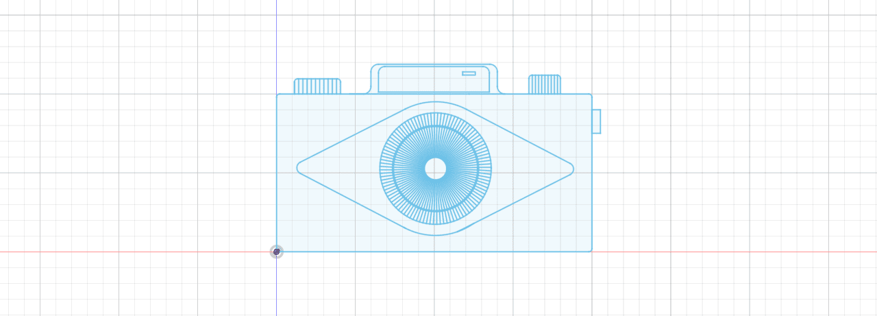
The steps I performed on Fusion 360 to draw the vector drawing of the camera are as follows:
1- I selected the Front plane and click on Sketch.
2- I drew rectangles and lines to draw the shape mostly.
3- For curved parts I applied Fillets.

4- For the eye balls, I drew one circle and created the other two by creating Offset Paths. An example of how I used it can be seen below.

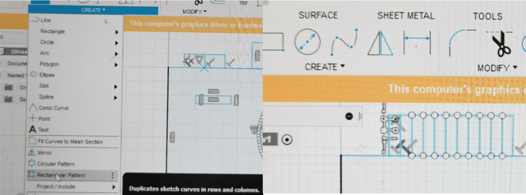
5- To create the continuous lines of the eye balls, I drew one line and created a Circular Pattern.
6- To delete extra length of lines I used the Trim feature.

7- For the continous straight lines on the upper knobs, I drew one line and created a Rectangular Pattern.
REFLECTING ON FUSION 360
This assignment work was my first time working on Fusion 360 and I am glad I got introduced to it as, for a free software, it has a really huge range and works great. However, I found its 3D modeling features a bit challenging to work with hence why I just decided to use it for vector design for now.
3D MODELING WITH TINKER CAD
MY WORK ON TINKERCAD - A BIRD HOUSE
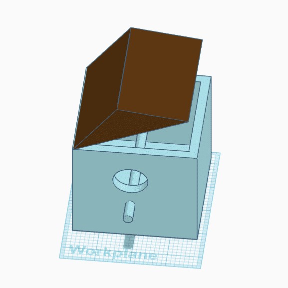
Since it was my first time on this software, I decided to follow a tutorial first and I have modeled this bird house entirely with the help of this YouTube Tutorial.
REFLECTING ON TINKERCAD
Before this assignment I had no idea about Tinkercad's existence and was introduced to it by my instructor. Though I had several other softwares I could try, its cute and simple interface made me want to try it. The 3D models created on TinkerCad can be downloaded and directly 3D printed which I think is great. Moreover, After you finish creating your model it also has an option to export the model to Fusion 360 if we want to take our design even more further which makes it even more cool.
3D MODELING WITH SOLIDWORKS
MY WORK ON SOLIDWORKS - REVERSE VENDING MACHINE FRAME

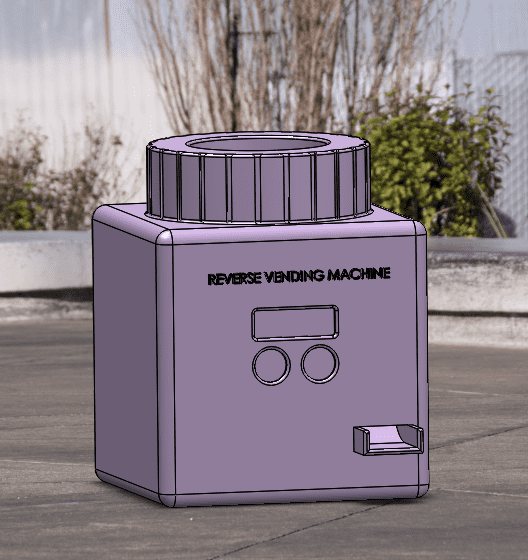
Since I will most probably be making a machine that detects and accepts plastic material which is most commonly represented by plastic bottles in the reycling world as its discarded very quickly and on a regular basis, I decided to shape my frame in the form of somewhat like a water bottle!
I performed the following steps to design the frame:
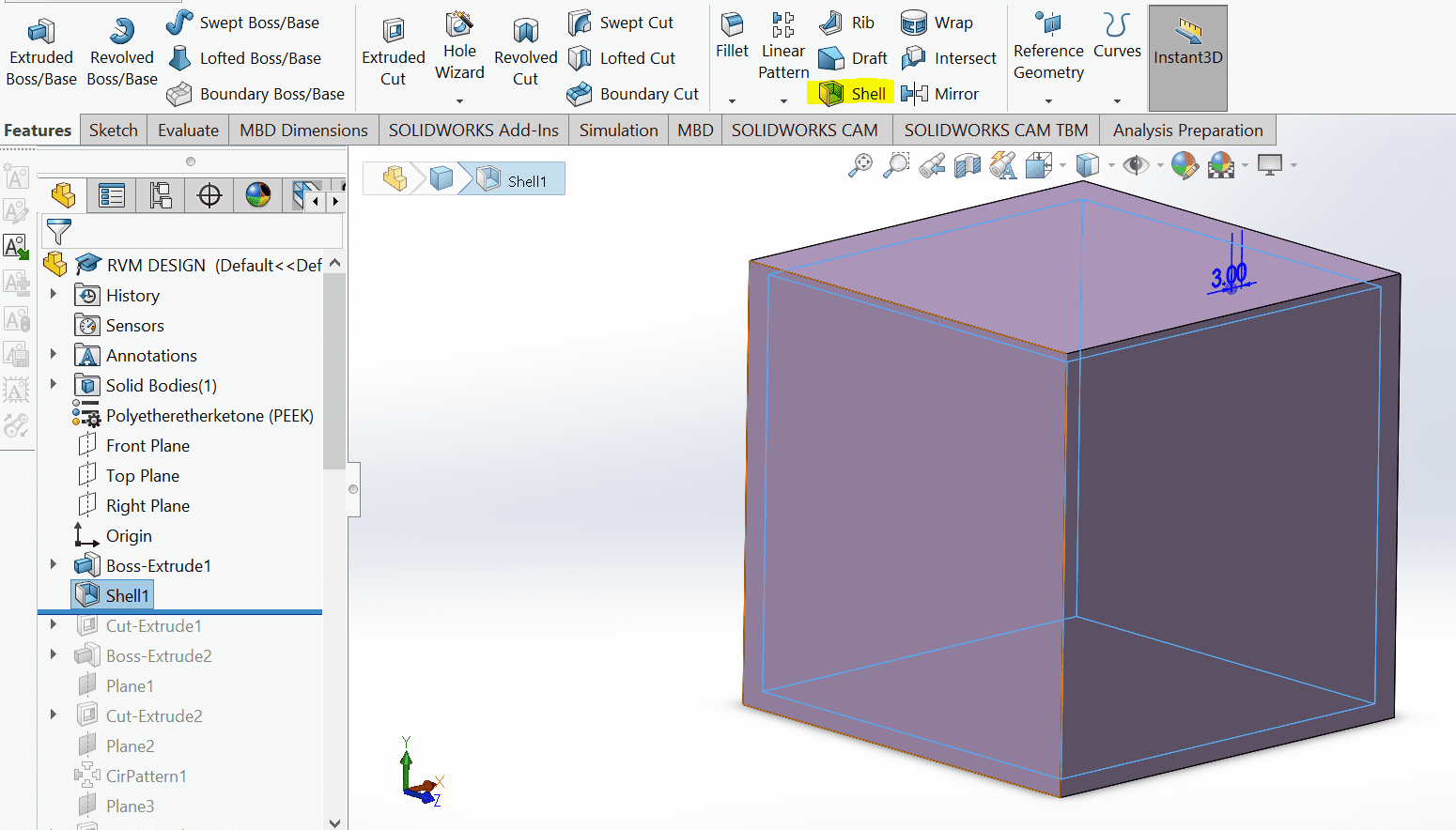
1- I started by drawing the basic square shop on top panel and extruding it and then made it a shell shape.
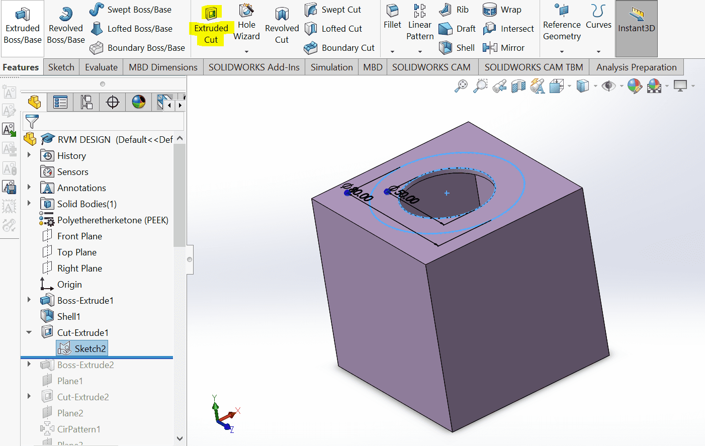
2- To make the cap shape, I drew 2 holes on the top panel. 1 to extrude cut a hole into the box to make space for dropping the bottles. The outer circle to extrude above to make a cap shape.

3- Then I drew a square on the edge of the cap and extrude cut it till the surface. After that I applied the circular pattern to create a continuous effect.

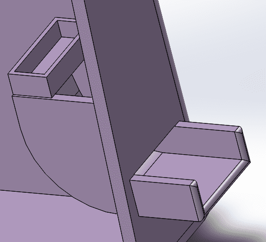
4- To make space for the screen and two button, one to confirm recycling and the other for reward I drew- 2 circles and 1 rectangle on the front panel and extrude cut again.

5- For the reward system I drew a sliding shape. The box instead can contain the coins which will slide out to the outside tray. (Seeing it now, the outer tray requires a boundary as well to avoid the coins from falling.
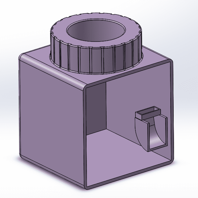
6- Lastly, I added fillets to the edges to make them smooth as seen in the final drawing.
REFLECTING ON SOLIDWORKS
To 3D model the body of my possible final project, I decided to use Soldiworks as I am the most comfortable with it and I wanted to focus more on designing instead of spending time on understanding a new interface. Solidworks has a very well structured, up to date and easy to understand user interface and anyone can become good at it within a few months of practice. The only unfortunate-side is that it is a paid software and therefore only someone who can pay can have access to it or students who are given a time limited license by an educational institute.