COMPUTER CONTROLLED MACHINING
The aim of this week was to create something big using the big wood sheet we were provided with on the big CNC ShopBot machine! This weeks assignments were divided into two parts:
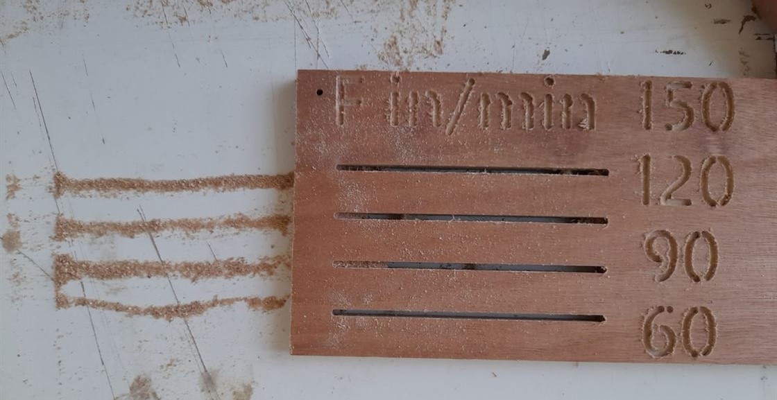
1. Group Assignment - This was a small CNC assignment testing feed rates and speeds with our instructor on an online session.
2. Individual Assignment - This is the assignment for which we were to design something, cut it on CNC and finally assemble it.
GROUP ASSIGNMENT
.jpg)
1. The vector drawing was imported/drawn the drawing sheet. Then go to Toolpath tab option from the left panel was selected.
.jpg)
2. In the toolpath tab, the first operation performed was Profile Toolpath to cut the piece.
.jpg)
3. After selecting the drill bit, Spindle speed was set to 14000 r.p.m and calculate button was clicked.
.jpg)
4. Before the simulation, the software opened up a dialog box to warn that the depth of the material cut is going to be more than the actual sheet thickness. Since we had a sacrifice sheet underneath we simply clicked OK.
.jpg)
5.This is how the simulation panel looked. The speed of simulation can be varied.
.jpg)
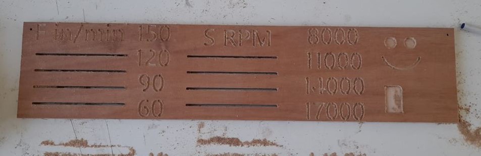
6. Then we tried Pocket Toolpath to cut the letters,numbers and emoji eyes To select multiple objects shift key is held while collecting all objects.
.jpg)
7. Feed rate was reduced for this.
.jpg)
8. Lines were cut using the 2D Profile toolpath.
.jpg)
9. The corresponding spindle speeds were set to try out and notice the effect on cutting quality by different spindle speeds.
.jpg)
.jpg)
.jpg)
.jpg)
.jpg)
.jpg)
.jpg)
.jpg)
.jpg)
.jpg)
10. The blue lines show the cutting by the drill bit. After the machining we saw how the different speeds and feeds effected the chips resulting from the machining and the finishing of the cut.
INDIVIDUAL ASSIGNMENT
DESIGN PROCESS
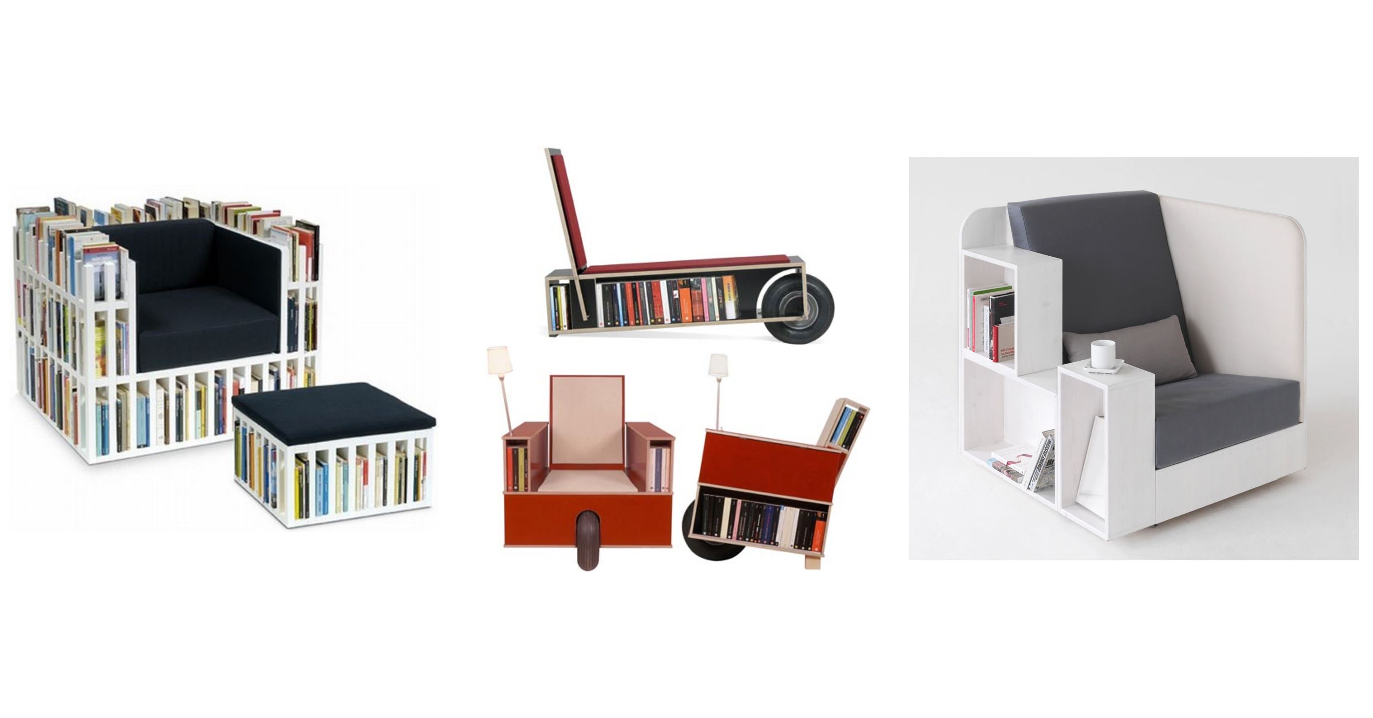
I am a big time fan of multi-functional furniture so I decided to design something like that. The hardest part in this assignment for me was finalizing an idea because the possibilities were endless! At first I had thought of making a carrom board table with a detachable covering plate that could also be used as a tea table, then I thought of a standing bookshelf with a hanging bulb support on top but eventually, I decided on a book-shelf chair design.
RESEARCH
As the CNC design especially for furniture was new to me I spent alot of time researching about the CNC design process, the suitable softwares, what has been done already. I also searched design ideas that I had in mind in order to find the best way to execute my idea within the material constraints. Some of the Book-Shelf Chairs that inspired my design can be seen below.
COMPUTER AIDED SKETCH AND MODELING
Before sketching the final design I modeled some designs on tinkercad to get some idea of the final model. An example of it can be seen below.
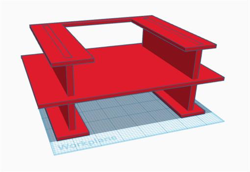
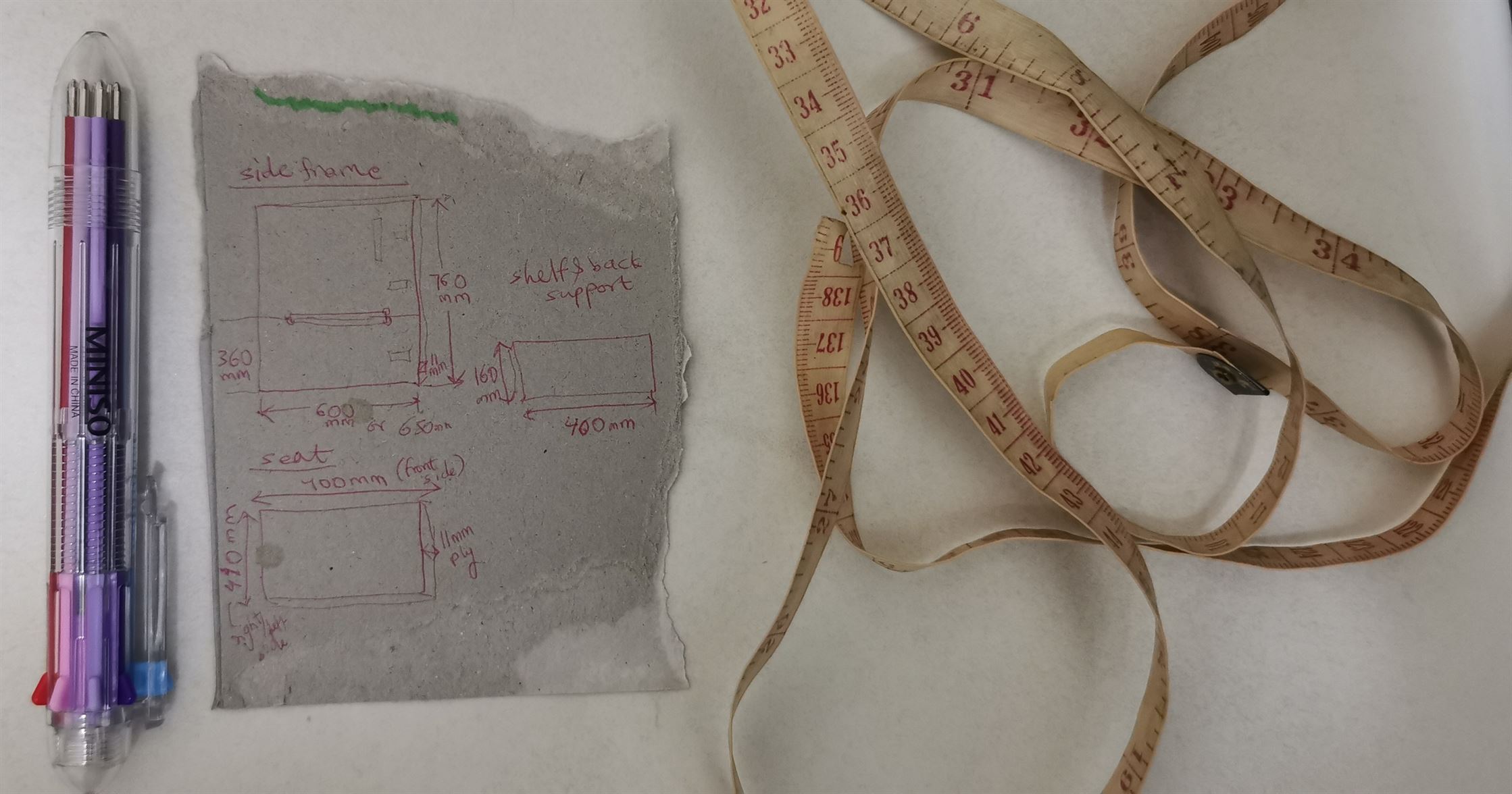
Then I took some approximate dimensions from a chair in my house.
We were introduced to Japanese joints wood joinery by our instructor during the theory session.
Its wood joinery without the use of nails and glue. I found them interesting so I incorporated them in my design.
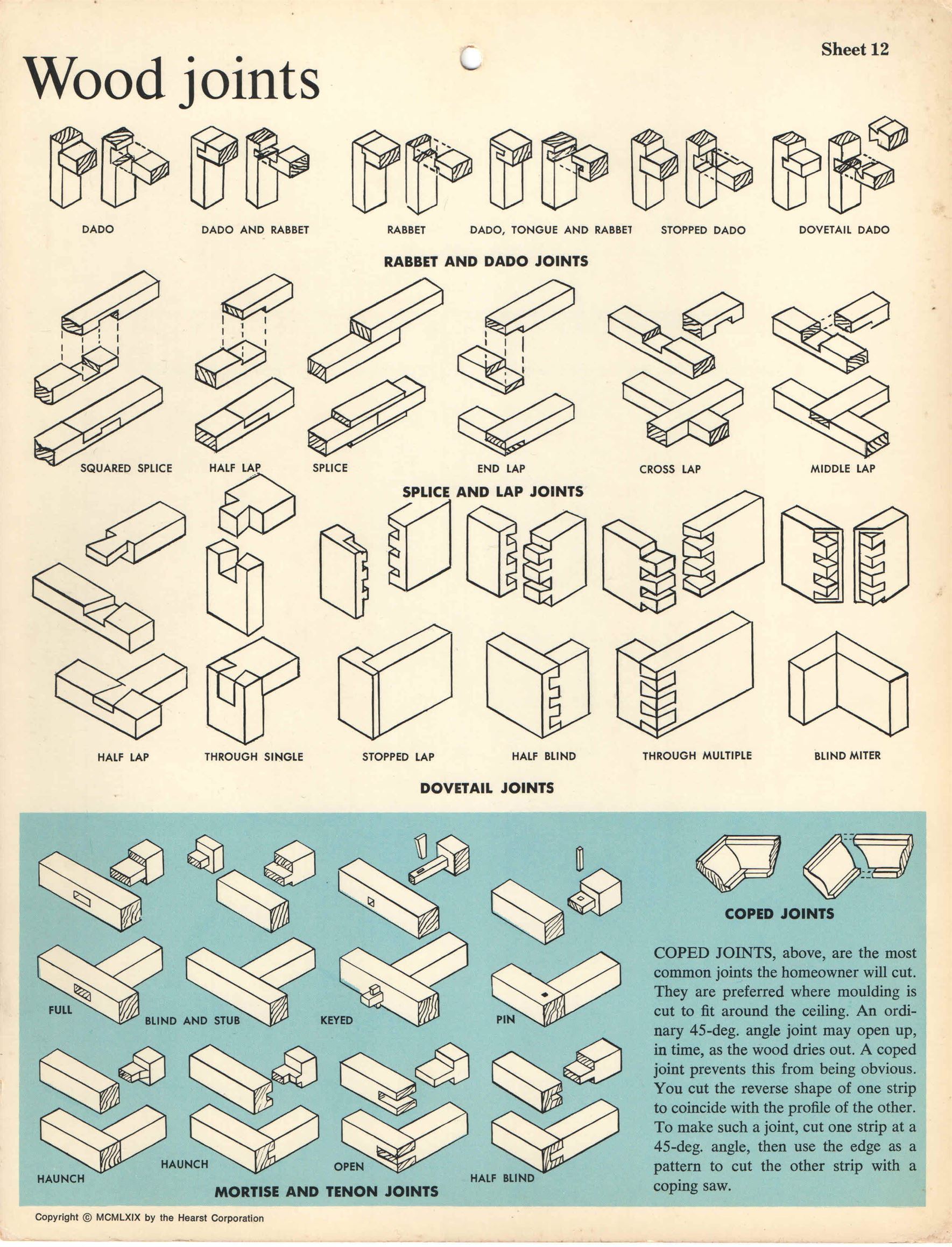
For joints dimensions, I referred to this joints test image sent to us by our instructor.
.jpg)
.jpg)
After, having a clear idea in mind I sketched all the parts of the chair on Solidworks.
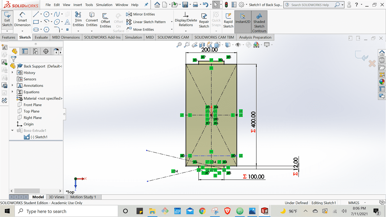
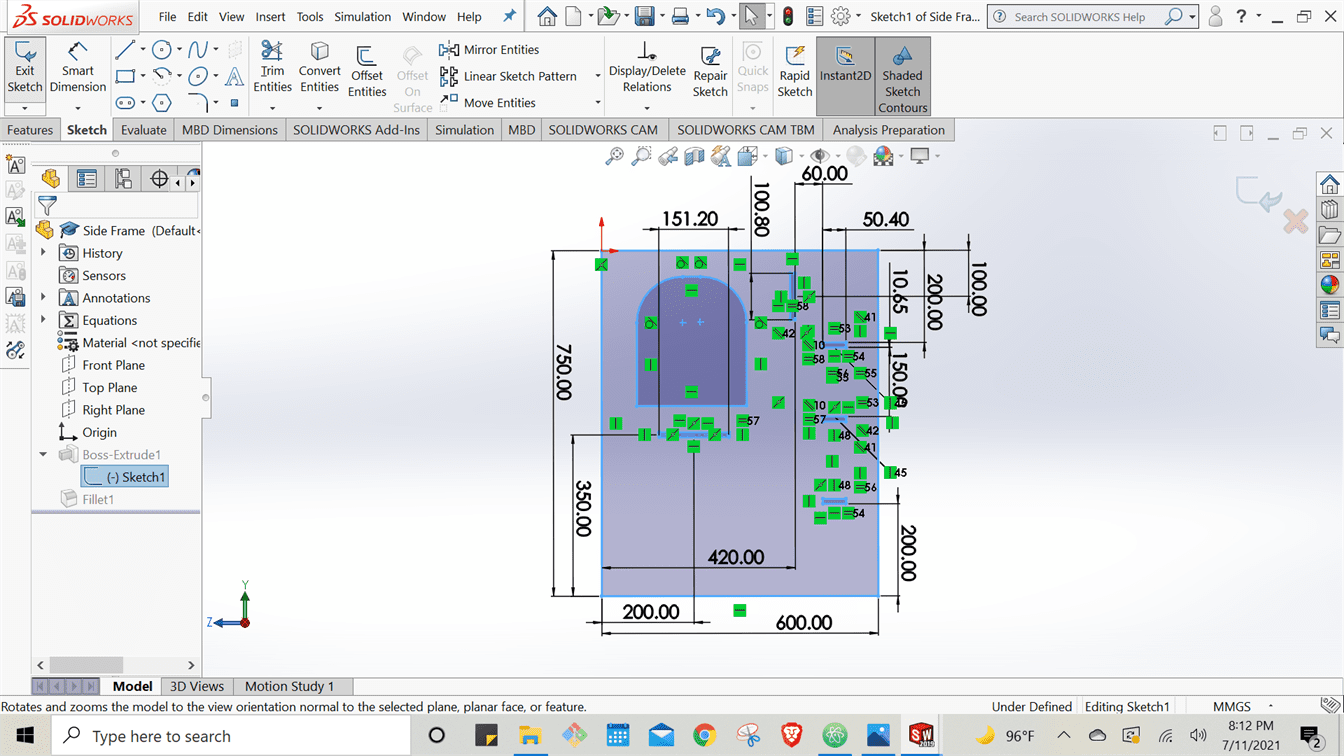
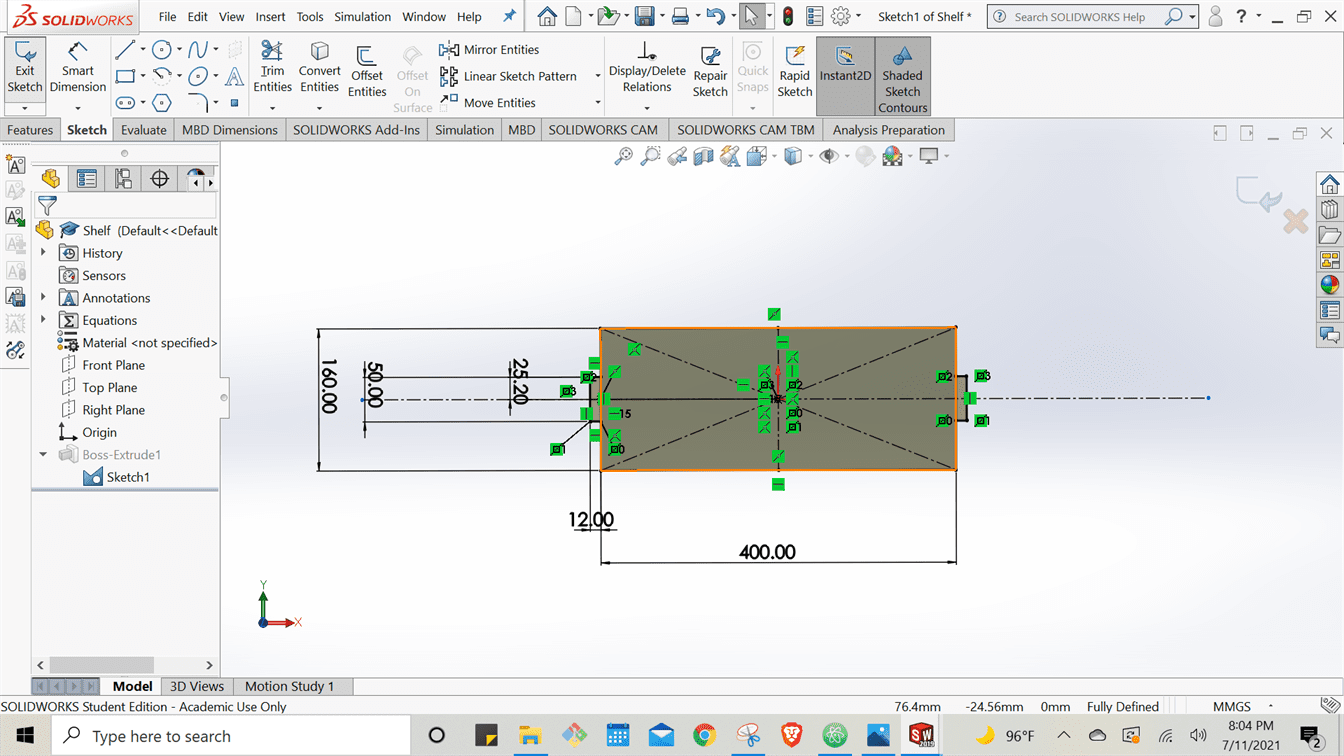
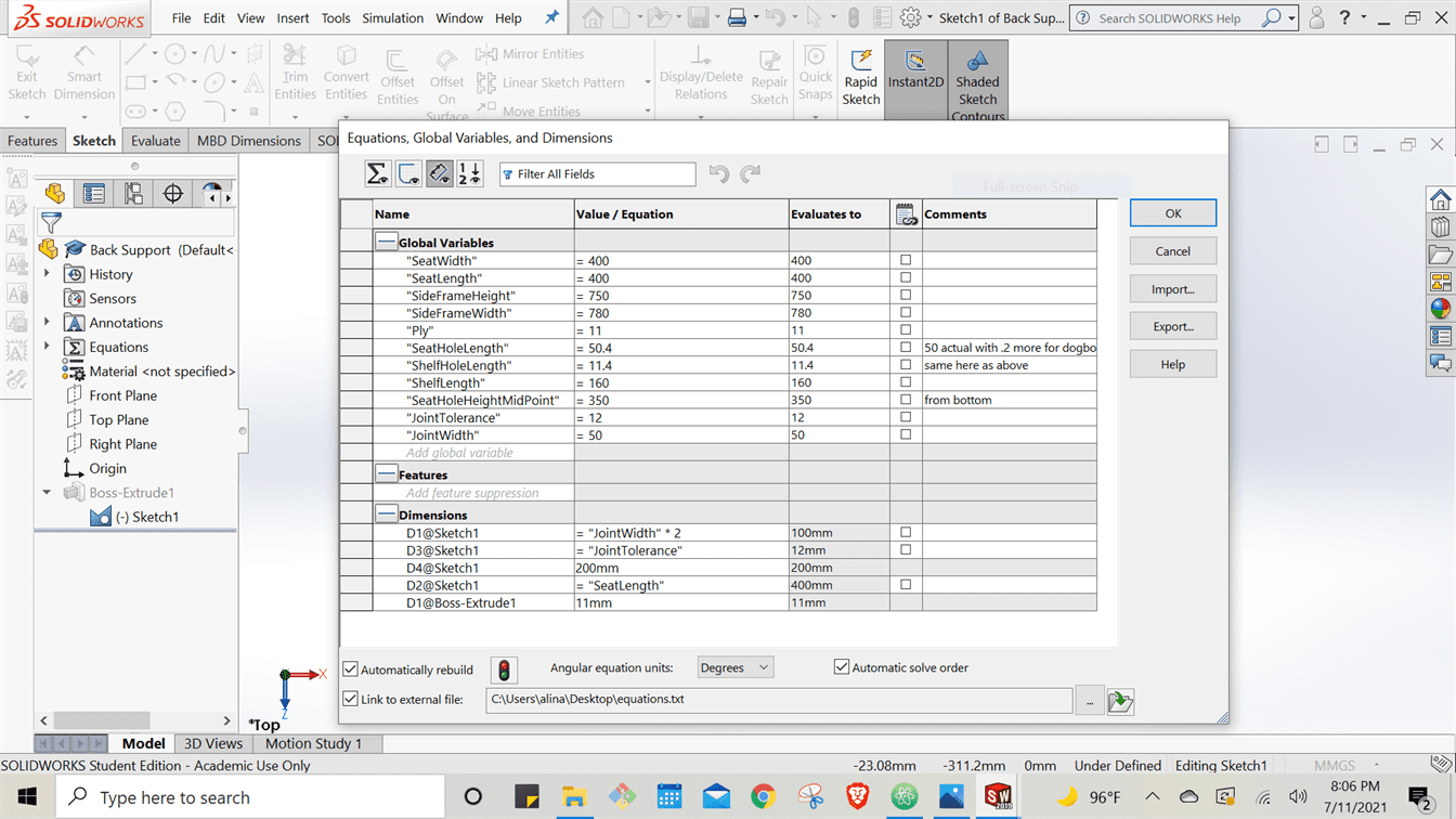
The sketch was made to be parametric so that if I would have to change a dimension last minute I could simply change the dimension at one place to update it everywhere in the design automatically.
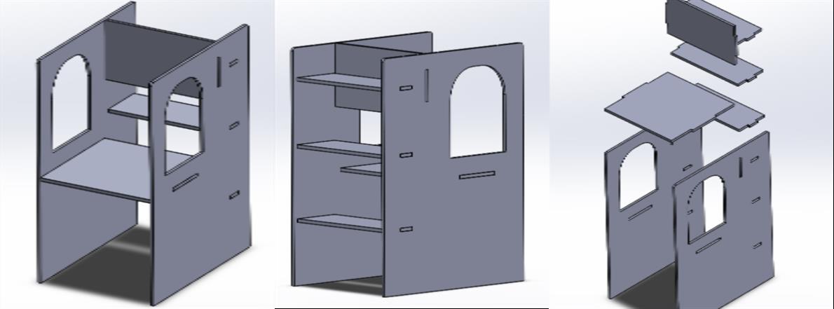
After designing the parts seperately I assembled them on Solidworks as well in order to understand the joints more clearly and also check for any interferences. Finally saved all the components drawings as .dxf files i.e., as simple 2D vector drawings to import on VCarve Pro.
NESTING FOR MACHINING
Nesting for machining means laying out all the components on the wooden sheet for cutting which I did on VCarve Pro.
The following steps were performed to do it:
1. Set the Job Size i.e., the height, width and thickness dimensions of our wood sheet.
.jpg)
2. Created an inward offset border to the sheet. This is done because our sheet is joined with a sacrifice sheet beneath it with the help of nails and if our drill bit were to collide with it, it could result in an accident. Therefore, we drew the offset rectangle to place our drawings in that instead.
.jpg)
3. Imported my drawings on 2D vector design drawings (.dxf files) on VCarve Pro and arranged them on the sheet by selecting each component and dragging them over the sheet to the desired place. This can also be done automatically by the software.
.jpg)
❗ In this step I experienced an error, which was that my sketch was not 'joined' i.e., when I selected the component it only selected the line of the component that I selected. To solve this, we selected the entire component sketch by dragging the mouse sketch from above left to below right. Then we used the 'Join Open Vectors' command on the panel on the left to make the sketch whole.
.jpg)
.jpg)
4. After nesting, I added T-Bone fillets to my vector sketches. T-bone fillets are added because we use circular drill bits that are incapable of cutting sharp rectangular edges on the inside which can effect our joints. T-Bone fillets allow space for the drill bit to create a rounded path as per its nature.
.jpg)
.jpg)
After nesting and confirming the dimensions one final time we move to the toolpath tab.
.jpg)
MACHINING PROCESS
GENERATING G-CODE ON VCARVE PRO
G-code is a programming language for CNC (Computer Numerical Control) machines. G-code stands for “Geometric Code”. We use this language to tell a machine what to do or how to do something. The G-code commands instruct the machine where to move, how fast to move and what path to follow. This is done through the toolpaths tab on vCarve Pro.
The following steps were performed to generate the G-code:
1. We set the material set up by adding the depth we want the machine to cut. This was kept a little more than our original wood sheet thickness as we wanted to make sure the pieces would cut through.
2. We selected the desired Toolpath Operation. The main was the profile toolpath which cuts the profile of the pieces.
.jpg)
3. When toolpath operation is selected, a new panel opens to set the cutting depth for the operation as well as to select the tool i.e., the drill bit.
The tool setting consists of two parts, Firstly a tool is selected. Secondly it is edited, to set our own spindle speed, plunge rate, etc.
.jpg)
4. After tool settings come the Tab settings. These tabs are just small segments of uncut areas that hold the piece in place. After all cutting is done, you manually cut these tabs away and extract your piece from the plywood.
.jpg)
5. Finally, the Calculate button at the bottom is clicked to view the simulation of how / in which direction the drill bit will move and cut.
.jpg)
6. Finally, we save the toolpath operation as a file to our computer to use it for our cnc cutting.
.jpg)
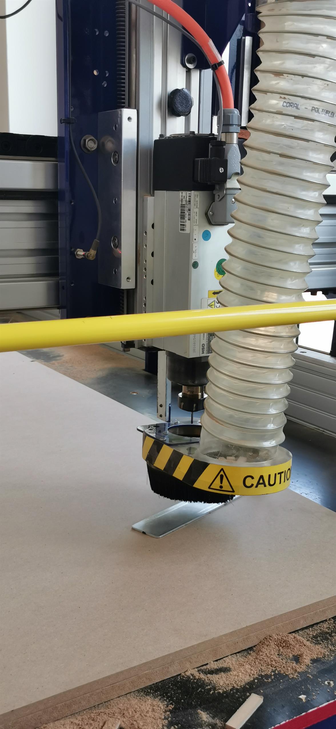
PREPARING THE MACHINE BED
After you have the G-code file you have to set up the sheet properly and also revise the safety precausions in order to avoid any possible accidents during the process. This is a brief process.
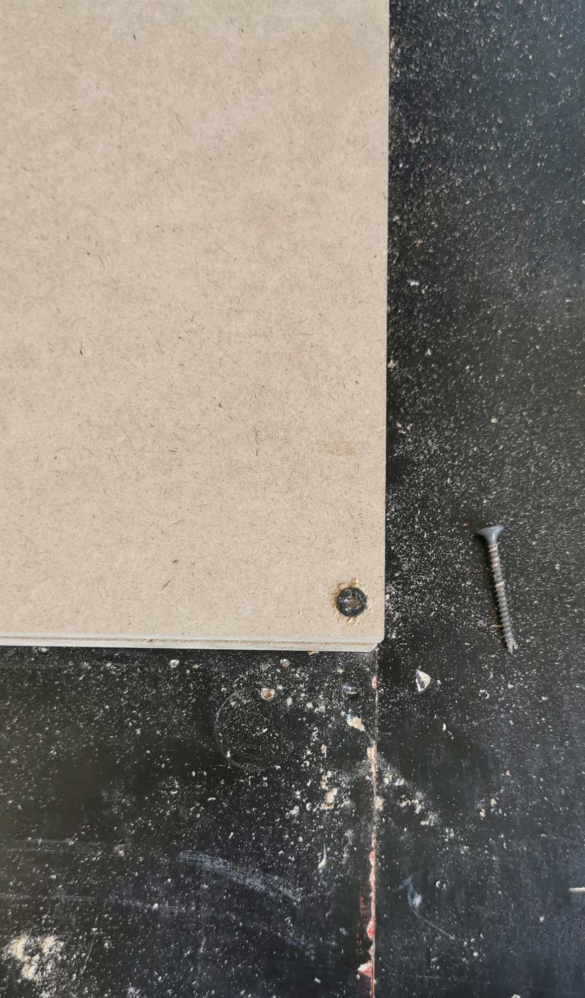
The new wood sheet is fixed on to the sacrifice sheet with the help of nails.
The next step is to set the x, y and zero axes to zero using the machine controls.
MACHINE CONTROLS
After preparing the working space we can switch on the machine.
The drill bit is moved with the help of a keypad control panel.
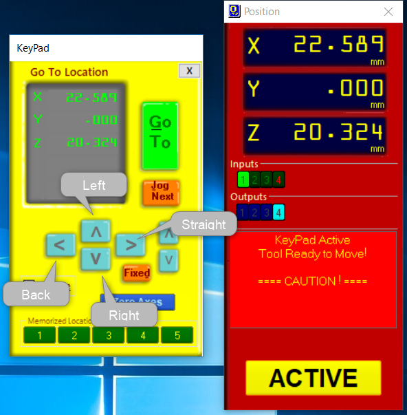
We first use it to zero the x, y and z axis.
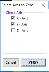
x and y can be set to zero simply by:
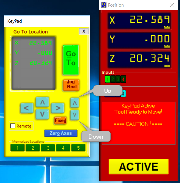
To zero the z-axis, following steps are carried out:
1. The machine is turned on and reset button is pressed.
2. The alligator clamp is fixed to the collet.
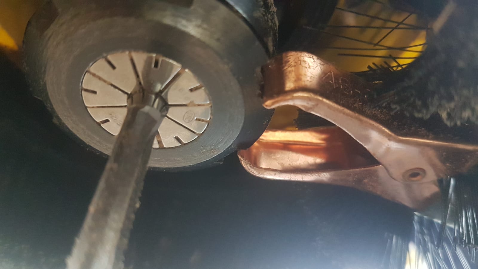
3. The plate is placed on the wood sheet at the starting point.
4. The keypad is used to bring down the drill bit and is made to touch the plate 2 times.
5. The Cut Part button is pressed which opens the laptops library from where we can choose our G-code file.
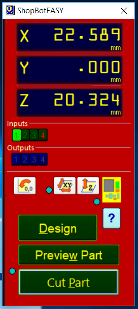
6. Finally, the START button on the keypad control is pressed and the automated cutting begins by the machine!
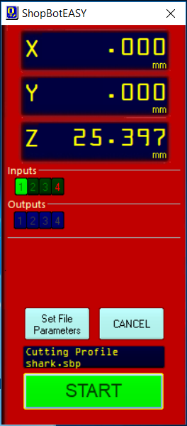
Though, it is advised to keep an eye on the machine in case the drill bit starts moving in the wrong direction, in that case stop bottom has to be pressed immediately. Additionally, one should also pay heed to the sound of the machine which can give some idea about how suitable the r.p.m. speed is.
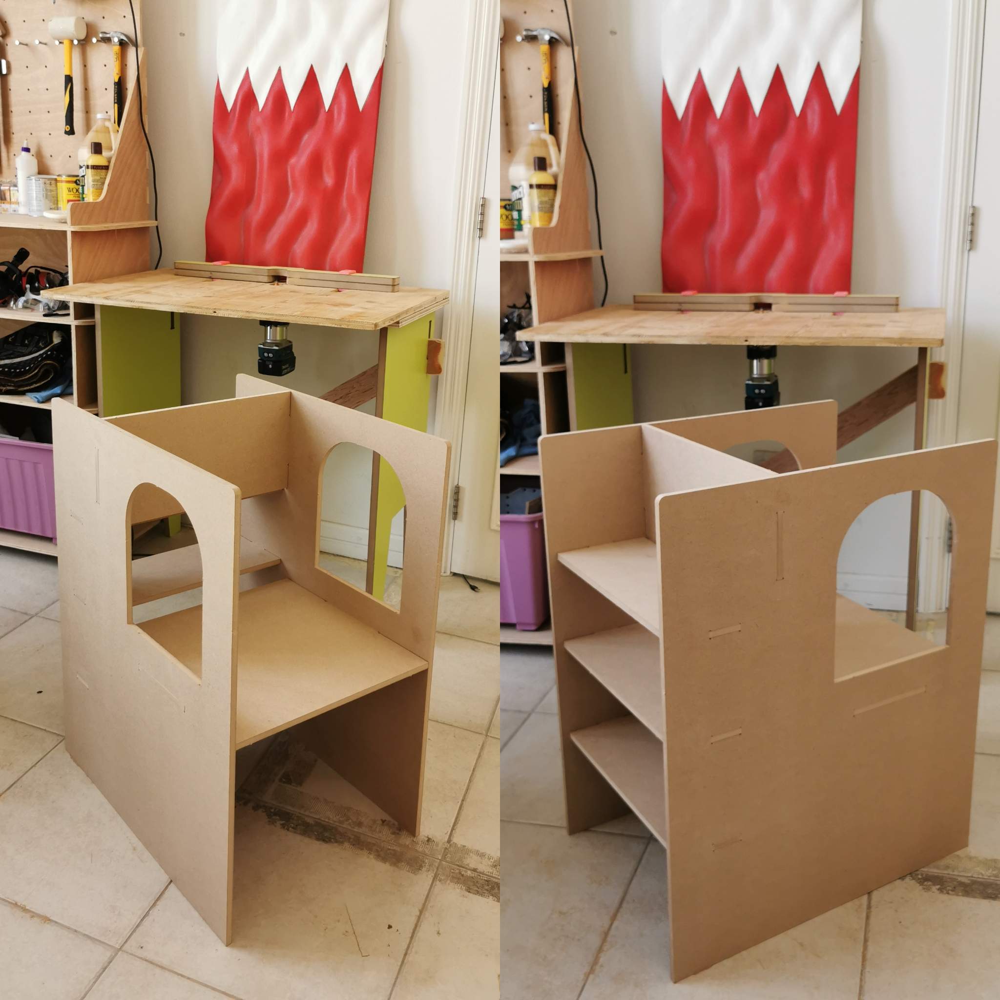
ASSEMBLING PROCESS
After the parts are cut by the machine they are taken out from the machining space by breaking the tabs and finally joined together. My design contains japanese joints so I should not be requiring any nails or glue.
Tools I used for fixing the joints were a Mallet and Filer which can be seen below:
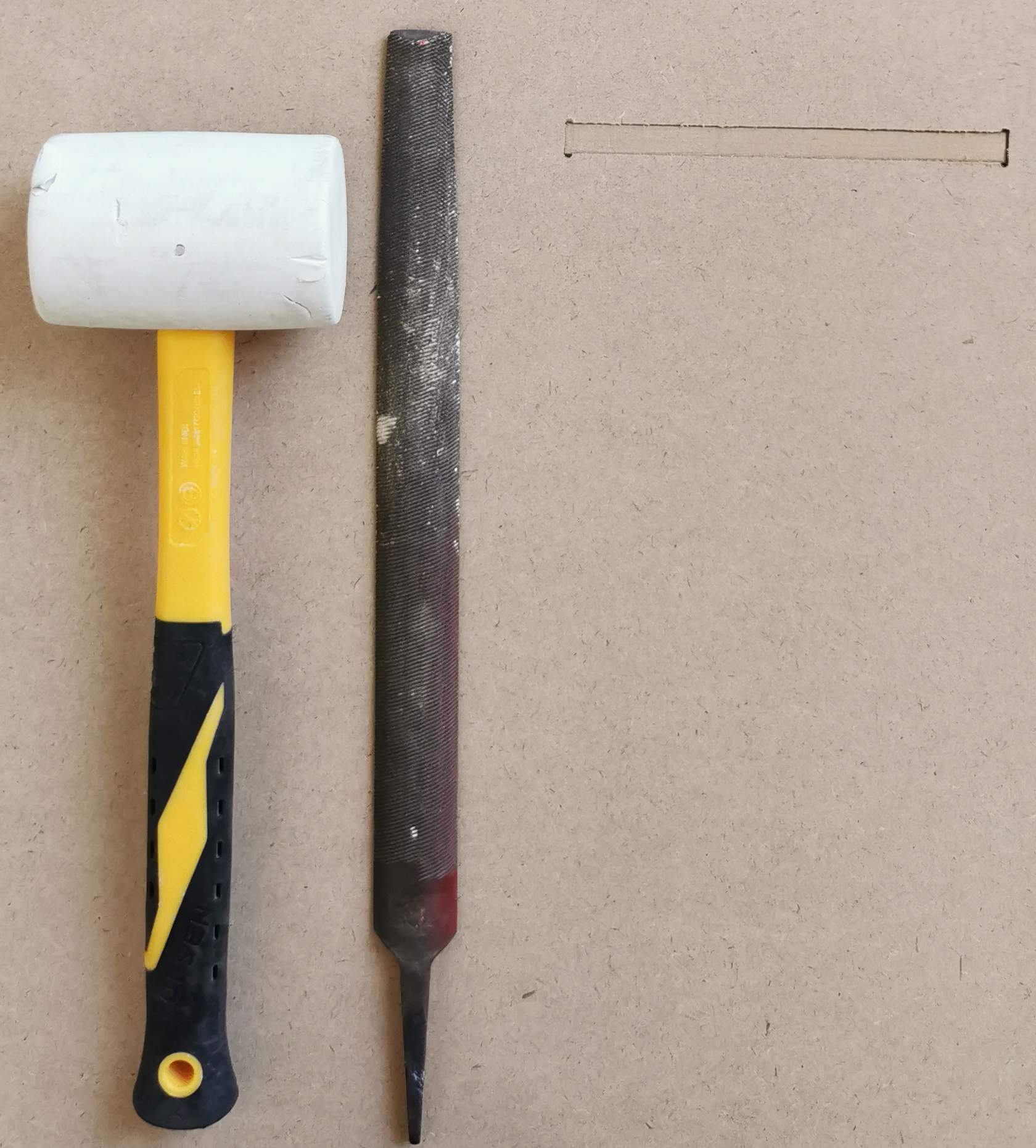
This is the final assembly:
✨ FINAL LOOKS ✨
HERO SHOT
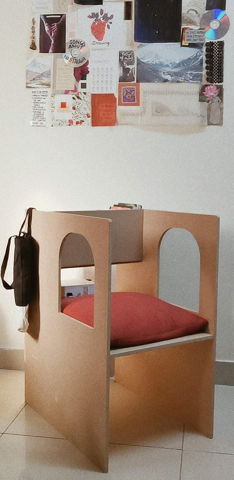
HERO SHOT
Since I was doubtful and scared the entire time in regards to such joints and the strength of my chair and thought it would fall as soon as someone sat on it :p I have decided to add a picture of myself sitting on the chair for any scared human who comes across my page as a proof that the the joints and design works!
Due to lack of a better title and humorous purposes only (I promise) I am calling my picture....
HEROINE SHOT =P