3D PRINTING & SCANNING
This weeks assessments were divided into two parts:
1. 3D Printing: The aim of this assignment was to create a 3D computer aided design that cannot be created subtractively
and mainly requires additive manufacturing.
2. 3D Scanning: The aim of this assignment was to 3D scan an object.
WHAT IS 3D PRINTING?
3D printing, also known as additive manufacturing, is a method of creating a three dimensional object layer-by-layer using a computer created design. 3D printing is an additive process whereby layers of material are built up to create a 3D part. This is the opposite of subtractive manufacturing processes, where a final design is cut from a larger block of material. As a result, 3D printing creates less material wastage.3D printing is also perfectly suited to the creation of complex, bespoke items, making it ideal for rapid prototyping.
WHAT IS 3D SCANNING?
3D scanning is the process of collecting data from the surface of a physical object which accurately describes the shape in terms of three-dimensional space. Once collected, this data allows technicians, mechanics, engineers or hobbyists the ability to examine an object digitally, which enhances and maximizes the precision and speed of their work. By obtaining the shape of the part digitally, the scan data can be used to either replicate the part (reverse-engineering), or for dimensional analysis (inspection).
GROUP ASSIGNMENT
In a group, we looked at different experiment models based on different settings set on the 3D printer. The models were as follows:
1. Infill
This setting is for, as the name indicates, inside filling of the 3D object. This can be done in multiple patterns such as grid, zig zag, etc. This also determines strength and quality of the print.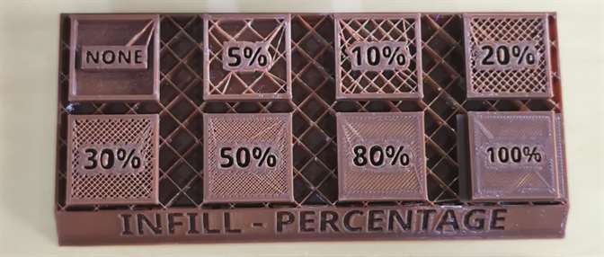
2. Shell
This setting is for the outline of the object. This maybe set higher if we wish to have stronger printed object.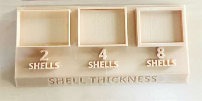
3. Layer Height
The printing pen prints the object from bottom to top in layers. The layer height is the distance between those layers. If it is less, the quality will be more fine but the greater it is the lower will be the quality.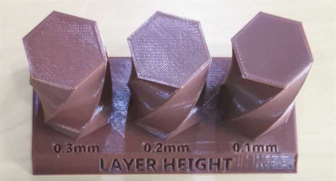
4. Overhangings
This setting is for designs containing curved paths and is set in degrees. The model shows how the more the angle is from the bottom surface, the weaker the print would be as the filament would experience too much gravity.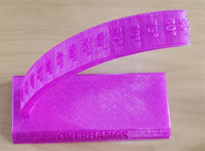
5. Supports
To avoid overhanging, supports are added in the design which can be broken out from the final printed design.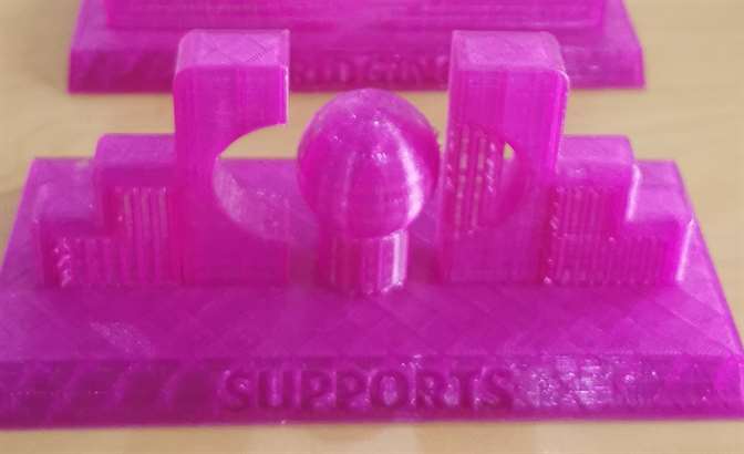
3D PRINTING
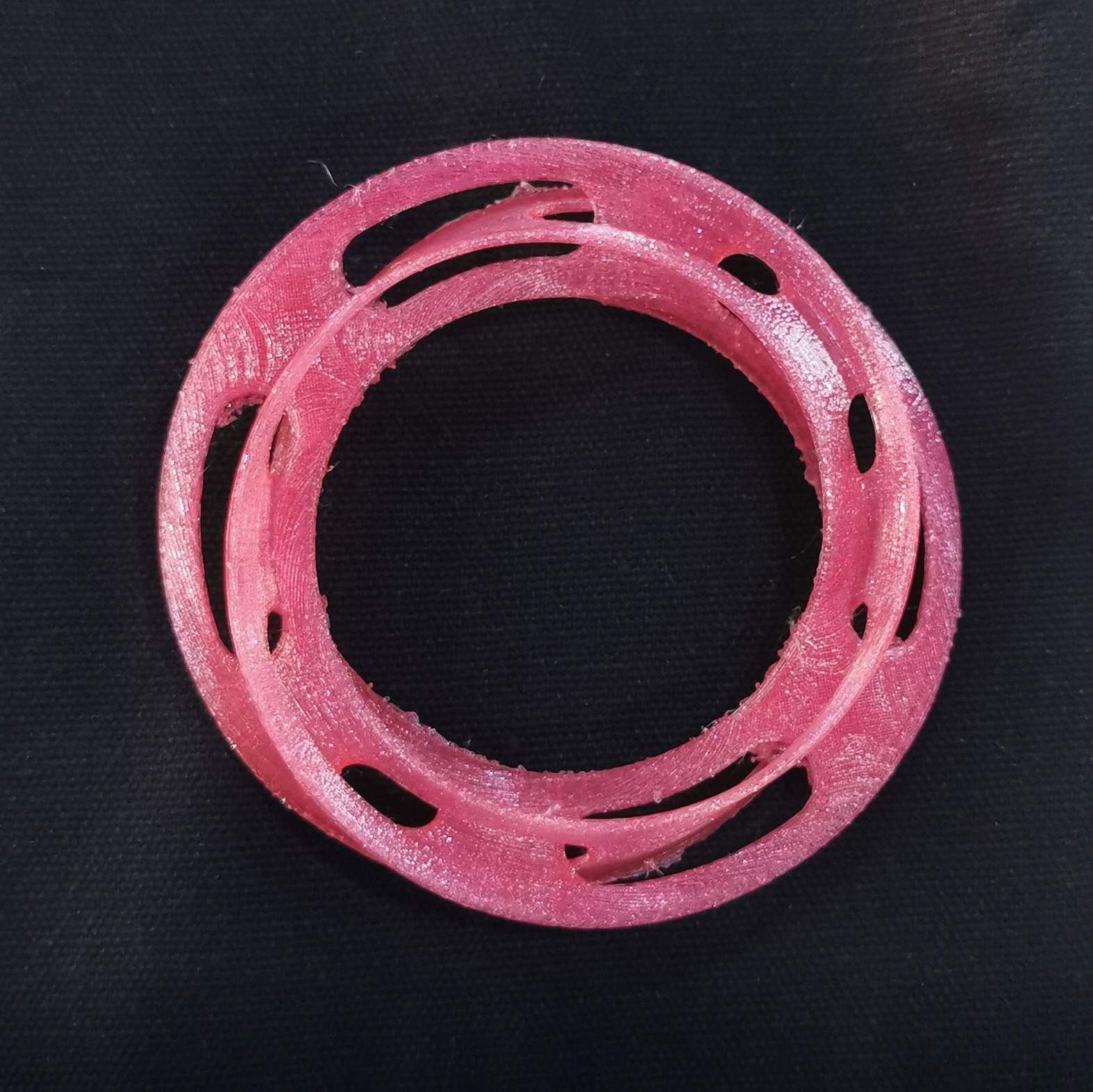
For this assignment I
created Interlocked Mobius Strips design on Fusion 360.
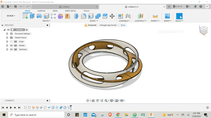
Interesting Theory Behind The Design:
The discovery of the Mobius strip led to new ways of studying the natural world, especially topology, a branch of mathematics that deals with the properties of a geometric object unaffected by deformations.
It’s one-sided, and only has a single continuous surface, which cannot be defined as inside or outside compared to a typical two-sided loop.
If a Möbius strip is cut lengthwise, dividing it in three equal parts,
it will result in two intertwined rings—one shorter strip inside a longer strip.
After reading this theory, I think it would be really difficult to design this subtractively. Moreover,
it's evident even from the design, the loose interlocking holes of the two strips
as well as the twisted body of the strips, would be extremely difficult
to make subtractively.
My friendly advice is that if you do not want to have your brain cells subtracted-
just make this design additively!
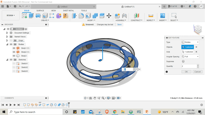
DESIGN PROCESS
The following steps were followed on Fusion 360 to create the design:
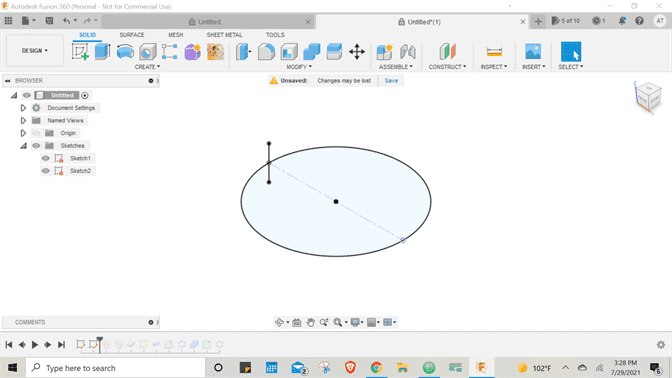
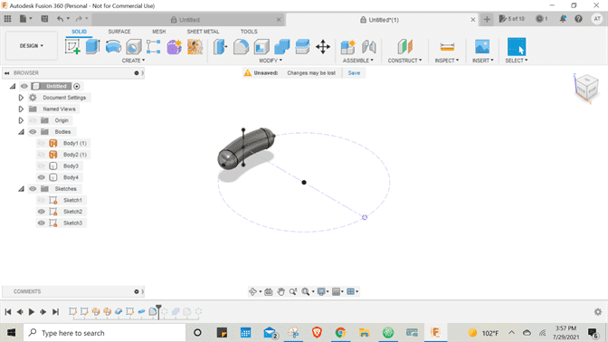
1. Sketched a Circle.
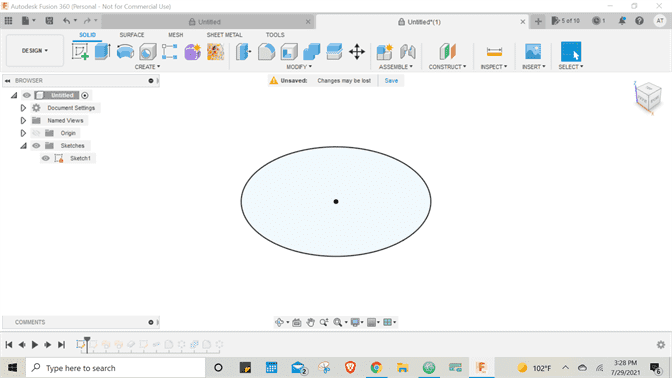
2. Sketched a Line tangent to the Circle.
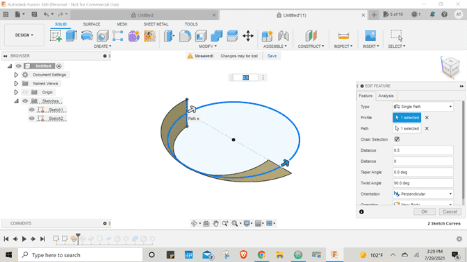
3. Sweep Surface was created using the Line and the Circle with a Twist Angle.
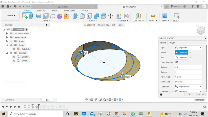
4. The surface was extruded using the thicken feature.
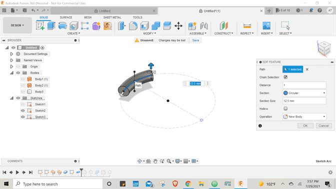
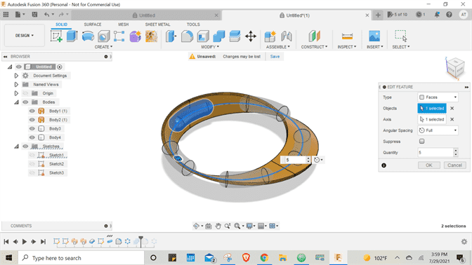
5. A line was created on the circular surface and extruded as pipe. On its faces, round fillet was added.
6. The hole was Patterned using the Circular Pattern option.
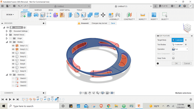
9. Then the hole bodies and strip body were combined and cut.
8. Fillets were added.
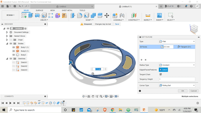
9. Circular Pattern feature was used to create the interlocking strip.
Finally, I saved my design as an STL file which was ready to be imported on to the
slicing software.
NOTE: I made the design with the help of this YouTube tutorial.
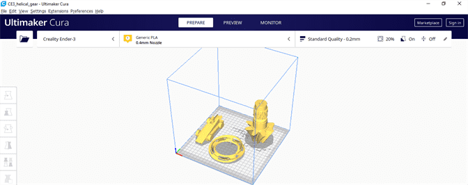
PRINTING PROCESS
The following steps were performed on
the Ultimaker Cura software to prepare the 3D print code file that the machine uses to print the designs.
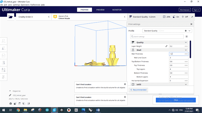
1. The design was imported on to the software and placed within the bed boundaries. You know your object
is placed correctly when its color is yellow, if it is grey that means you need to place correctly.
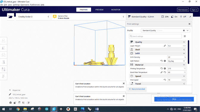
2. The following settings were set:
(a) Layer Height
(b) Shell
(c) Infill
(d) Supports
(e) Printing and Building Plate Temperature: The temperatures at which the filament is to be melted are set
and also of the extruder and building plate below.
(f) Print Cooling and Fan Speed: The print is made from melted filament which is hot so it requires cooling.
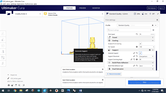
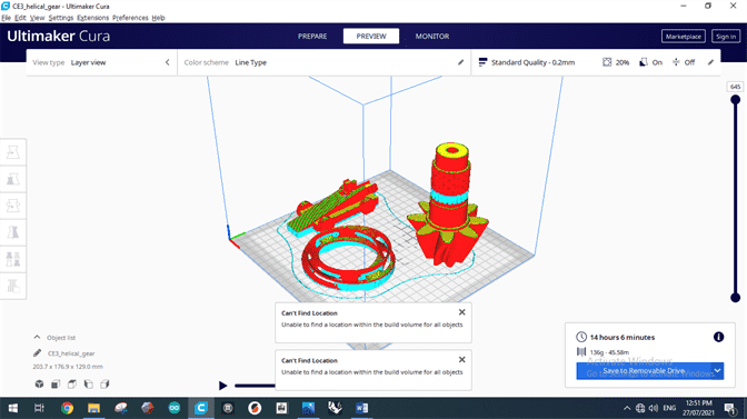
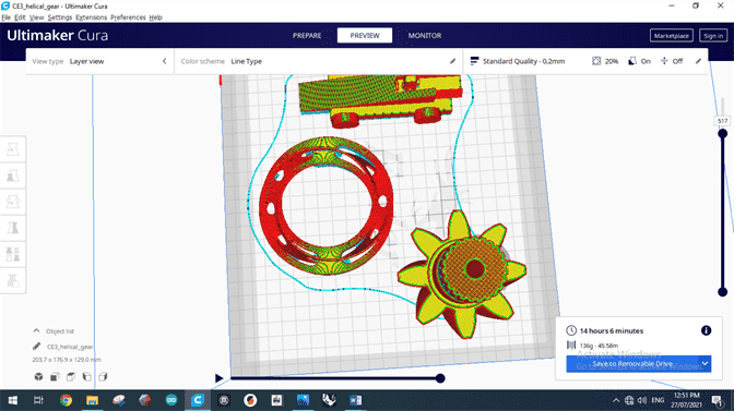
After the settings were set we clicked on 'Slice'Button which showed us
the amount of time and material the printer would take to make the design.
3. The design file was added on the machine with the help of SD card.
4. The flexible machine bed, which makes the design
easily removable from the bed, was set up by clipping it on all four corners on the fixed metal plate bed.
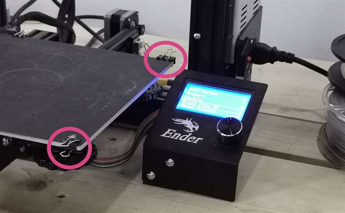
5. The file was chosen on the control panel.
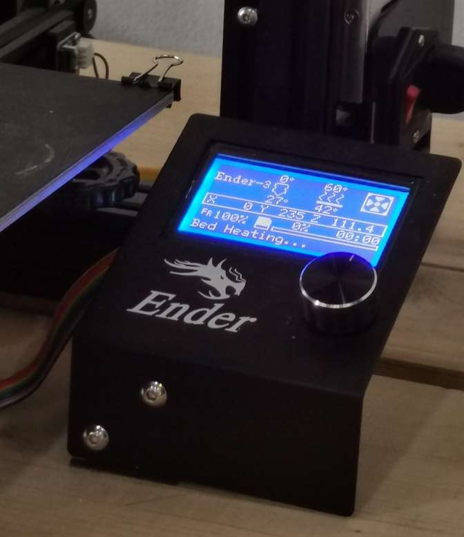
6. The machine controlled the rest of the material i.e., heating filament and extruding on the bed.
Lastly, as mentioned above, supports were added to obtain a stable and fine print so I had to remove them after the printing was done. The tools used and final result can be seen in the image below.
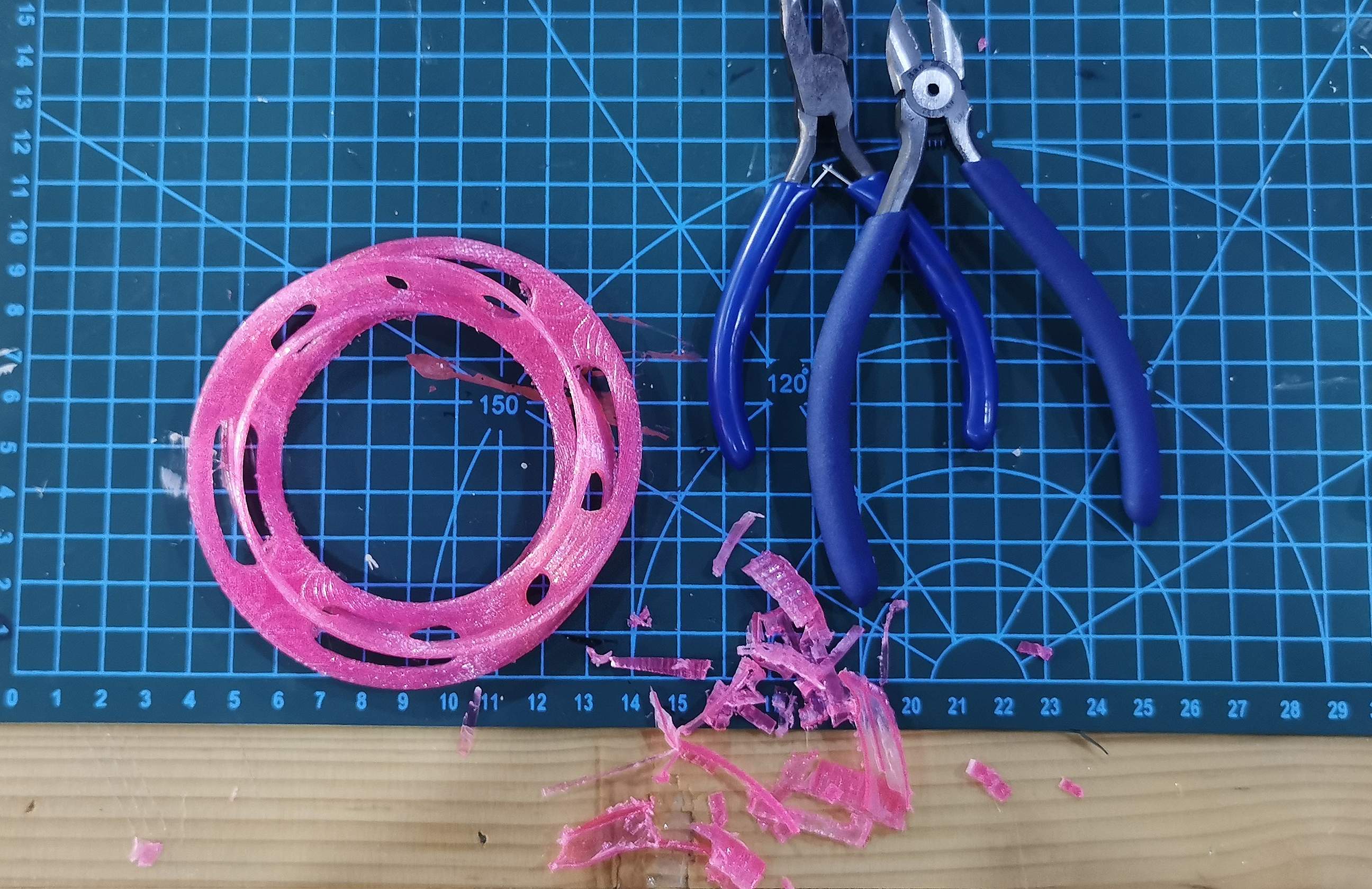
✨ HERO SHOT ✨
3D SCANNING
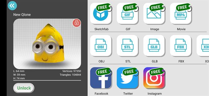
For this assignment I used
the Qlone application available on playstore.
The following steps were carried out to 3D scan the object:
1. The scanning mat page was linked on the app's website from where it was downloaded and printed.
2. The mat was placed on a flat open space and the object was placed in the centre of it.
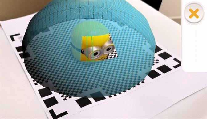
3. On the app, a blue boundary can be seen around the object being scanned.
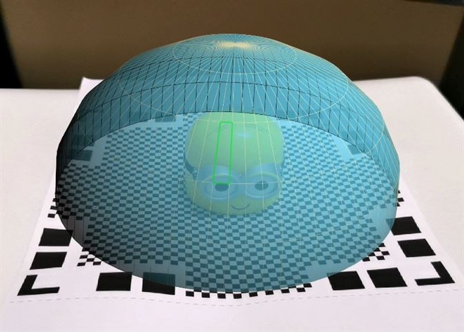
To scan successfully, all we have to do is move the mat/camera around the object which will
make the blue boundary disappear little by little and when it has disappeared completely
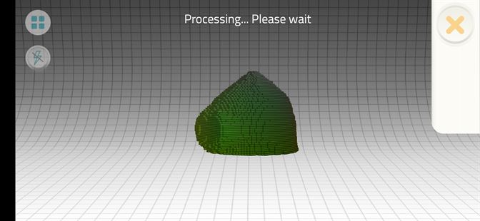
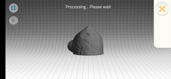
the app will automatically start processing the scanned object and show a colored
3D preview of it.
Lastly, I exported my file as an mp4 video file as the STL file format
for export was only available for premium users.