EMBEDDED PROGRAMMING
The aim
of this week was to read our microcontroller's datasheet and get started with programming an Arduino board to do something.
Since we are just getting started we did not use any input or output devices and simply
programmed the embedded LED on the Arduino Nano board.
The softwares used were as follows:
1. Arduino IDE
Arduino is an open-source electronics platform based on easy-to-use hardware and software. Arduino boards are able to read inputs - light on a sensor, a finger on a button, or a Twitter message - and turn it into an output - activating a motor, turning on an LED, publishing something online. You can tell your board what to do by sending a set of instructions to the microcontroller on the board. To do so you use the Arduino programming language (based on Wiring), and the Arduino Software (IDE), based on Processing.
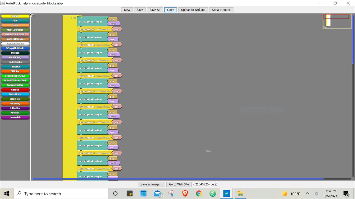
2. ArduBlock
ArduBlock is a programming environment designed to make physical computing with Arduino easier for beginners. Instead of writing code, worrying about syntax, and (mis)placing semicolons, ArduBlock allows you to visually program with a snapped-together list of code blocks. If you already have Arduino installed, you can download just the ArduBlock add-on, which is what I did with the help of this guide.
ARDUINO NANO
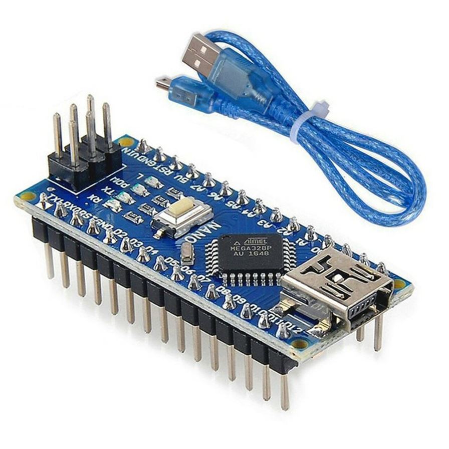
The microcontroller board we will be using is Arduino Nano. It is a small, compatible, flexible and breadboard friendly Microcontroller board, developed by Arduino.cc based on ATmega328p. Arduino Nano is simply a smaller version of Arduino UNO, thus both has almost same functionalities. It is programmed using Arduino IDE. This board doesn't use standard USB for connection with a computer, instead, it comes with Mini USB support.
ARDUINO NANO DATASHEET
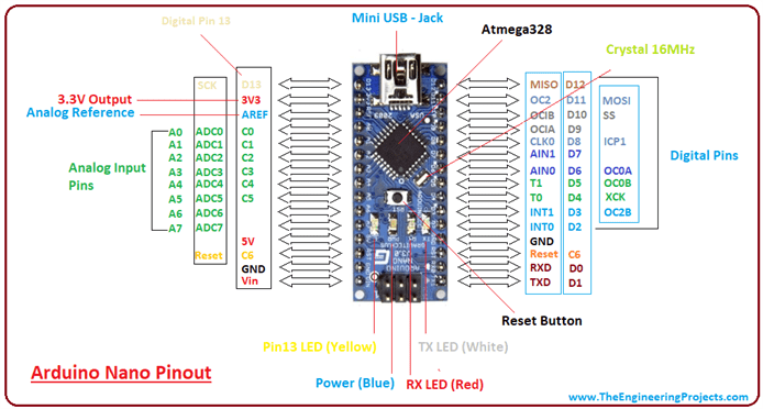
Arduino Nano Pinout contains 14 digital pins, 8 analog Pins, 2 Reset Pins & 6 Power Pins.
Each pin on the Nano board comes with a specific function associated with it.
Each of these Digital & Analog Pins are assigned with multiple functions but their main function is to be configured as input or output.
Functions like pinMode() and digitalWrite() are used to control the operations of digital pins while analogRead()
is used to control analog pins.

SETTING UP THE BOARD ON ARDUINO IDE SOFTWARE
Firstly we installed the Arduino IDE software and the Driver.
Then we connected our board to the laptop using the USB cable.
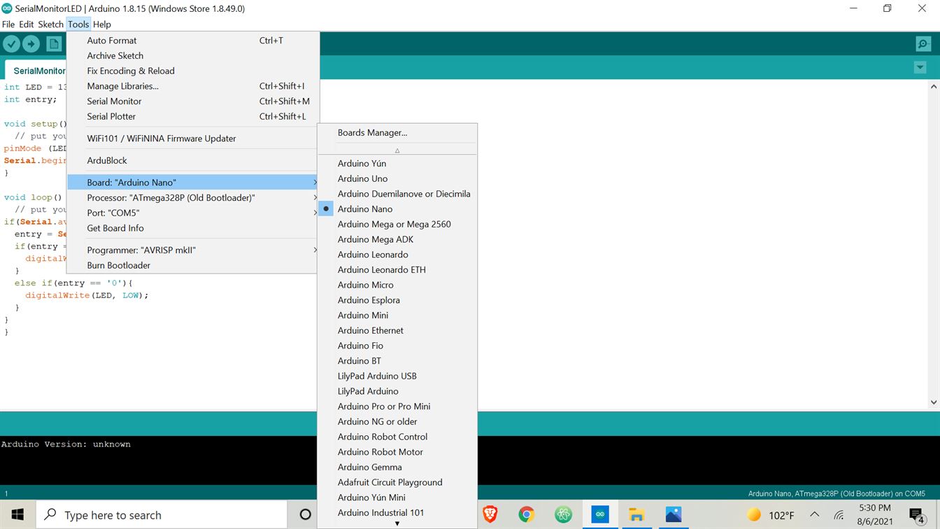
On the Arduino IDE software main page, the menu bar contains the Tools option which when selected, opens a drop-down menu.
This is where we finally connect the board to the software.
The following settings were set in the Tools drop-down menu to do so:
1. Board: Arduino Nano
2. Processor: ATmega328P Old Bootloader
3. Port - COM5
LED BLINKING USING BLOCK CODE
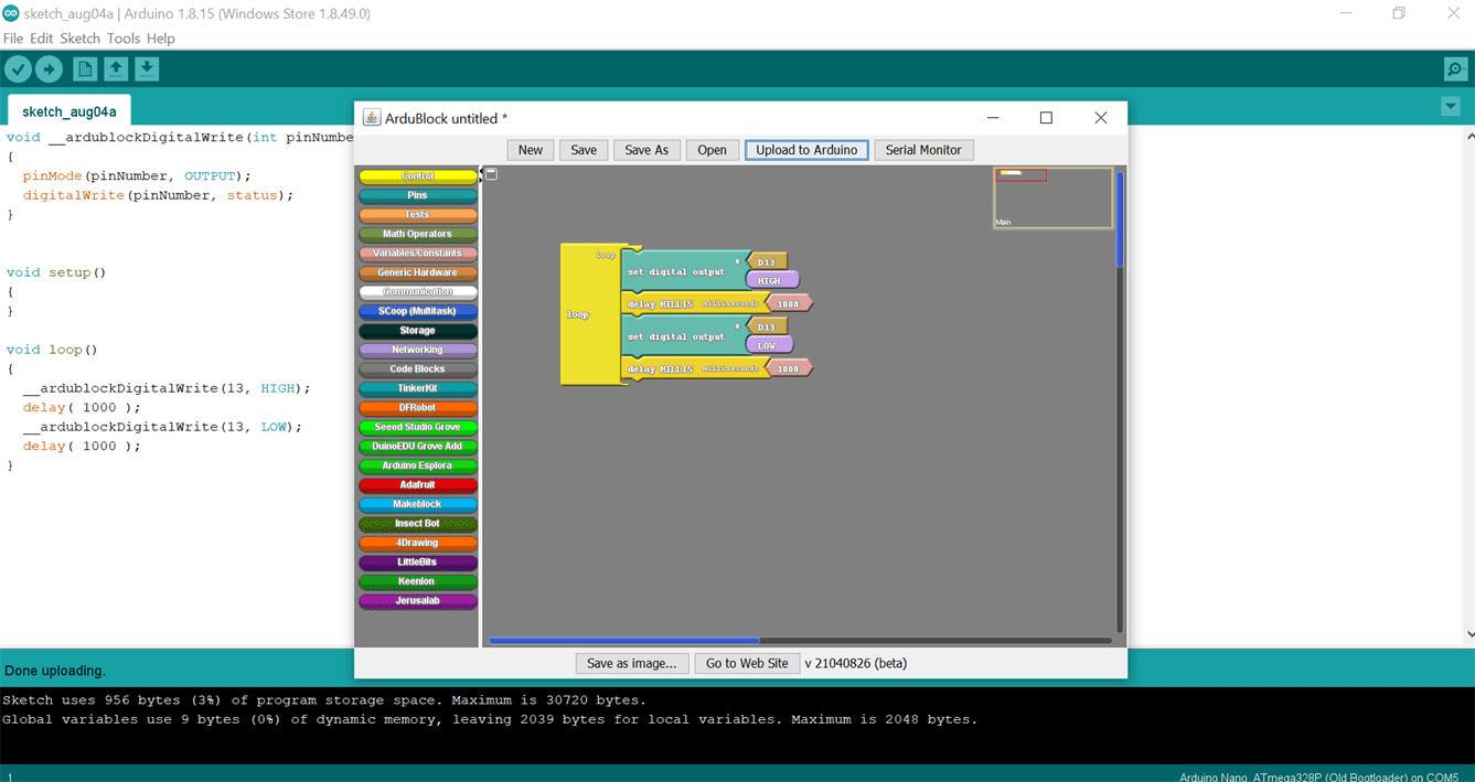
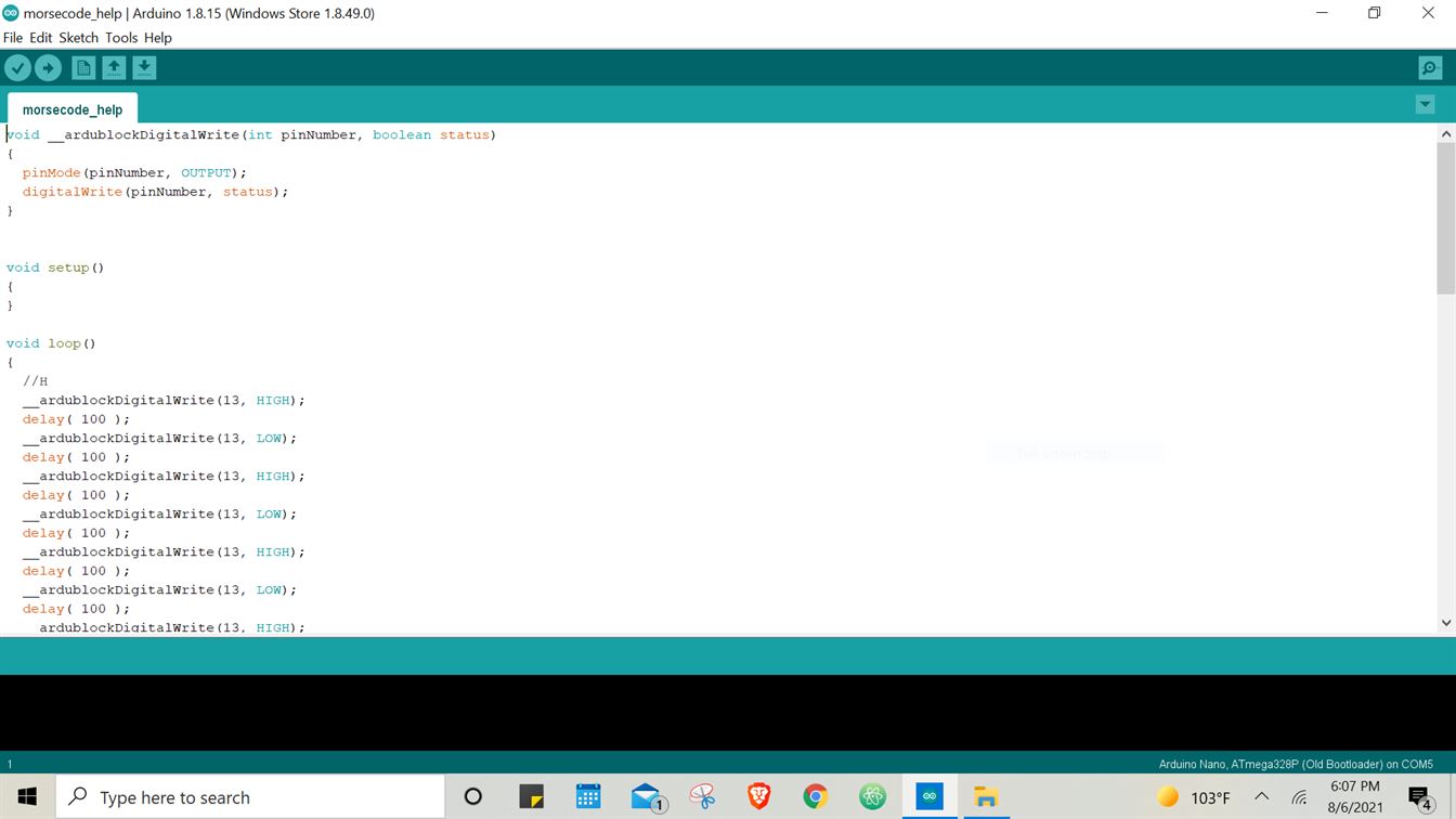
During our introductory session we uploaded an example Blink code already available on the Arduino IDE software. Since it was my first time with ArduBlock I decided to block code the blinking code. After my block code was done I clicked on the Upload to Arduino button on the menu panel above which converted my block code into a written code automatically!


📟 HERO VIDEO 📟
MORSE CODE USING BLOCK CODE
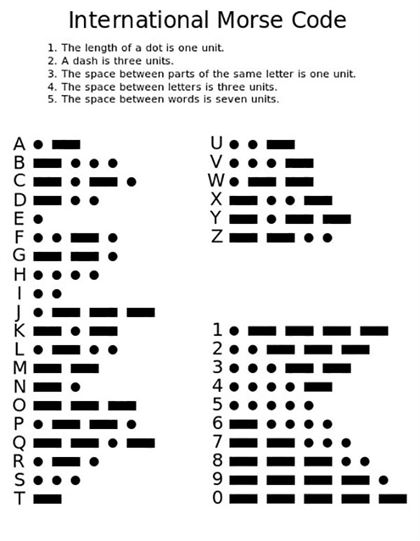
Morse code is a method used in telecommunication to encode text characters as standardized sequences of two different signal durations, called dots and dashes, or dits and dahs.
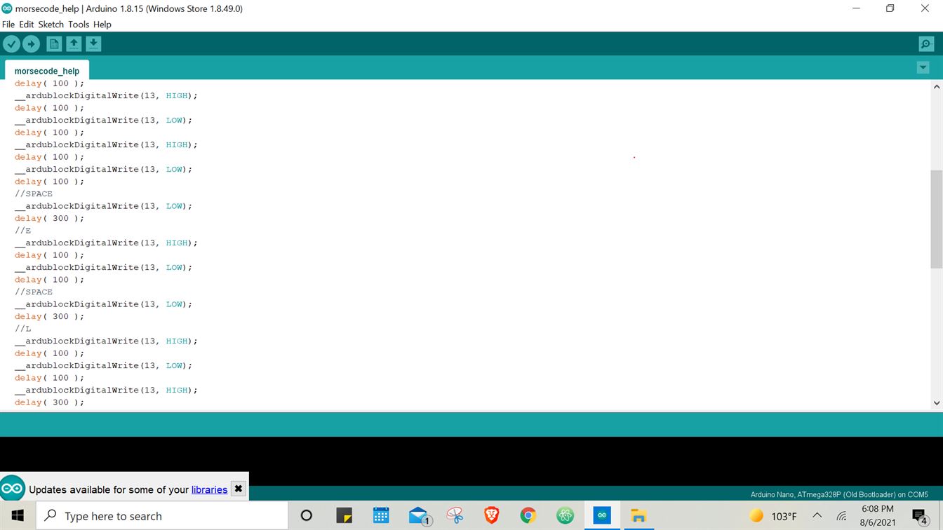
Each Morse code symbol is formed by a sequence of dits and dahs. The dit duration is the basic unit of time measurement in Morse code transmission. The duration of a dah is three times the duration of a dit. Each dit or dah within an encoded character is followed by
a period of signal absence, called a space, equal to the dit duration. The letters of a word are separated by a space of duration equal to three dits,
and words are separated by a space equal to seven dits.
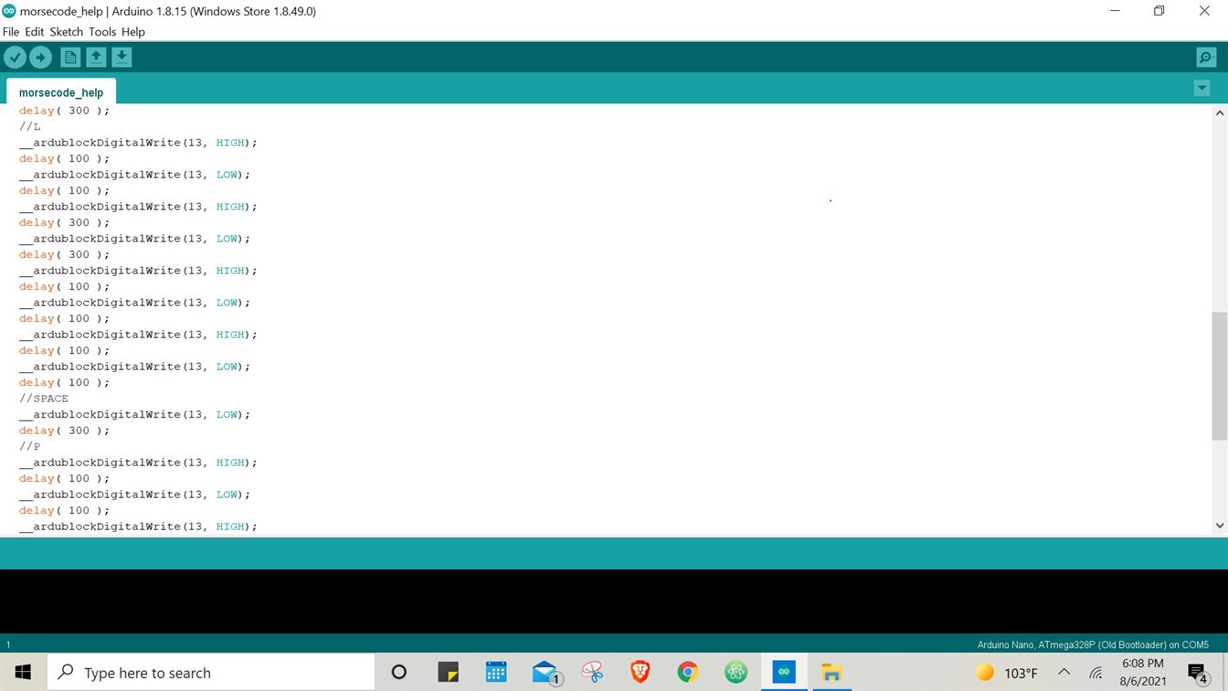
To program the dits and dahs I assigned a time duration of milliseconds to each of them. 100ms for dit and 300ms for dah. Then I simple utilized the delay function to set the timing for switching the
embedded LED on the board ON and OFF to communicate each letter. The word I have programmed is 'help'. I got the morse code for each letter from the International Morse Code sheet attached above.


📟 HERO VIDEO 📟
LED ON/OFF THROUGH SERIAL MONITOR USING C/C++ CODE
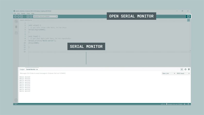
The Serial Monitor is an essential tool when creating projects with Arduino. It can be used as a debugging tool, testing out concepts or to communicate directly with the Arduino board.
My aim here was to switch the embedded LED- ON and OFF via user input on Serial Monitor.
To keep things simple and quick: If the user enters the number *1* the LED is switched *ON* and
if *0* is entered, the LED is switched *OFF*.
The code was written in the following steps:
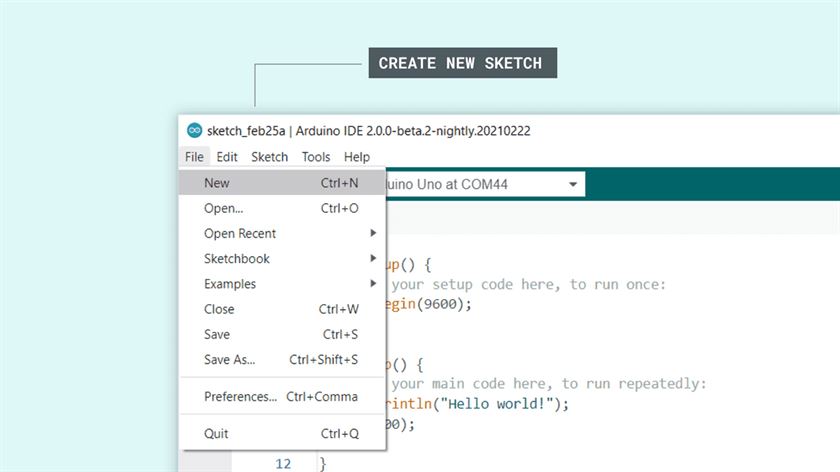
1. A new Arduino IDE software window was opened.
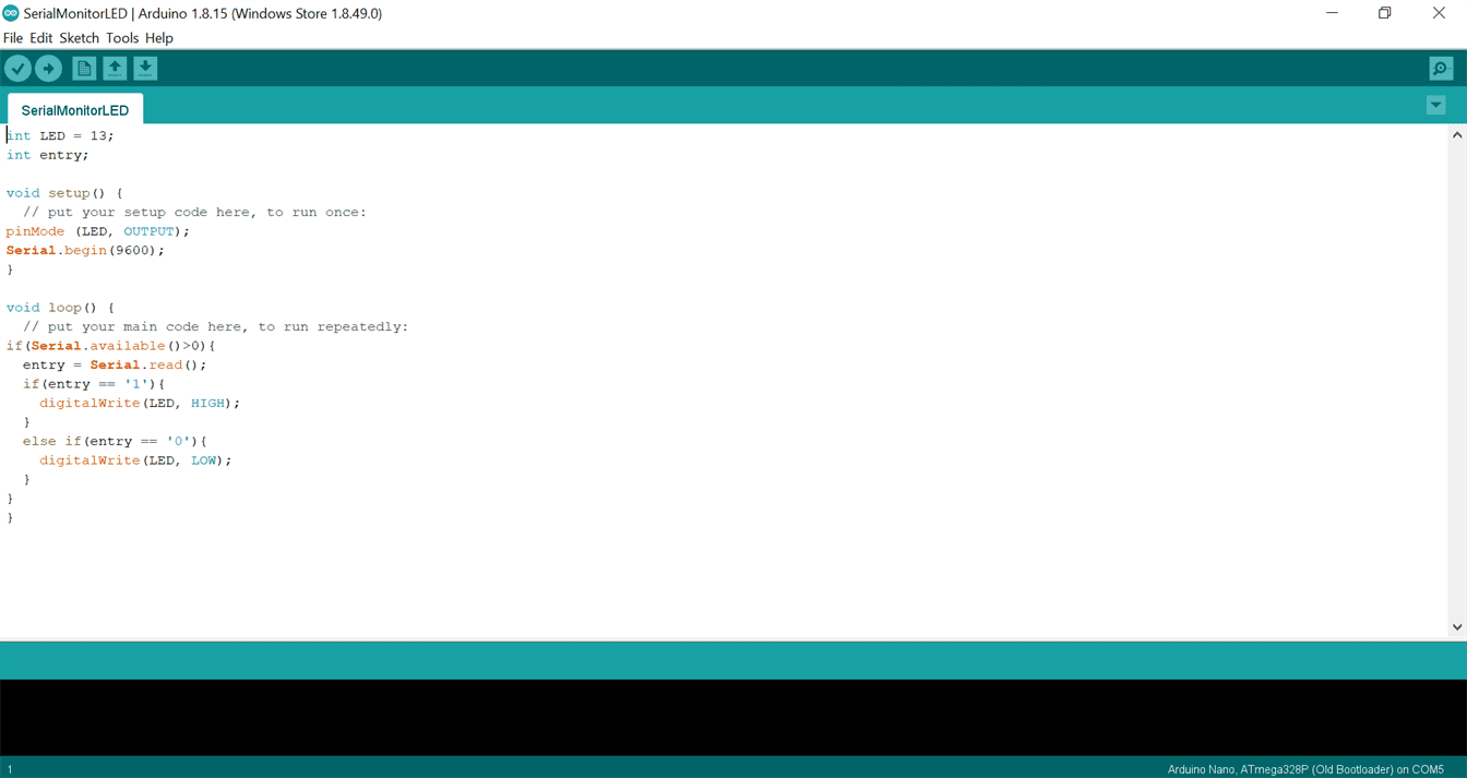
2. The embedded LED is connected to pin 13 on the board so I initialized that first.
3. Then I initialized a variable called "entry" to which the user inputs (1/0) would be assigned in loop.
4. In void setup (), I set the embedded LED pin as output.
5. Then I configured to communicate with the computer by setting up the
Baud Rate, which is done by writing Serial.begin(9600);. Here, the 9600 represents the baud rate,
which is the maximum bits per seconds that can be transferred.
6. In void loop (), 'if' statement is used to read any data that will be entered on to the serial monitor. Serial.available returns the number of characters that have been received and are ready to be read.
This line is making sure that you don't run that bit
of code unless there is actually some serial data there that is ready to read.
Inside this if statement, the 'entry' variable is called and Serial.read() is used to
read the characters that will be assigned to it from the serial stream.
7. Then using the 'if-else if' statement I coded the output of the LED on pin 13.
digitalWrite() writes a HIGH or a LOW value to a digital pin. If the pin has been configured as an OUTPUT with pinMode() , its voltage will be set to the
corresponding value: 5V (or 3.3V on 3.3V boards) for HIGH , 0V (ground) for LOW. Another important thing to note in the code is that, in C language,
the equality is represented with double equal (==) signs while assigning a value to the variable is
represented with a single equal (=) sign.
Lastly, I wrote the if-else if code as, if the variable 'entry' is equal to (==) 1,
the LED should be turned ON. else if the variable 'entry' is equal to (==) 0 the LED should be turned OFF.
8. Then I clicked on Compile option on the left of Upload option. I don't think
it is mandatory but it is like a final check for any errors in the code so I did that.
9. With my Arduino Board connected to my laptop and the software, I clicked on Upload option and also opened the Serial Monitor window on the side.

NOTE: Since I was working with C language after a very long time, I initially wrote the code with the help of this tutorial to ease my performance anxiety =p and once it worked successfully, I then studied each statement individually to understand the code as a whole.