INPUT AND OUTPUT DEVICES
The aim of this week was to use an input and an output device and program them to do something. My input component was a Photoresistor/Light Dependent Resistor which I used to control my output component which was a Servo Motor. The microcontroller used was Arduino Nano.
MICROCONTROLLER AND I/O DEVICES
A microcontroller is a computing device. Its main job is to perform computations…
it takes some data from its memory, manipulates them, and then stores them back to memory.
But having data in a microcontroller’s RAM doesn’t do much good.
In order to make use of that information, we have to be able to take it out of the microcontroller and
realize it in some way. To do that, a microcontroller has outputs that can transfer out bits of information
to devices that can display it, make sound or light, cause something to move, etc.
In many occasions though, we don’t have our data ready in advance. Some times, we want to transfer data in
the microcontroller as they become available. Other times, we want to let the user interact with the
microcontroller, or we want to sense different aspects of the environment around us.
For those reasons, a microcontroller also has inputs that let it take in information.
We are given access to the inputs and outputs (IO) of a microcontroller through the pins of its IC package.
The circuit behind each IO pin is built such that the user can configure that pin as
either input or output.
On an Arduino board, the pins of the microcontroller are organized
into groups and are given new names with which they are going to be referenced in the code.
[source: codebender]
PHOTORESISTOR / LDR
Photoresistors, also known as LDR (light-dependent resistors), are components made of semiconductors. A photoresistor is sensitive to light. Its resistance decreases when lighting increases. Photoresistor can be used for analog input. As it's a varying resistor, it can be used to drop the voltage that is present on an analog input pin. This change in voltage can then be detected and the application can react to it. Photoresistors have multiple uses, for example, automatic door opening. [source: digikey]
SERVO MOTOR
A Servo Motor is a small device that has an output shaft. This shaft can be positioned to specific angular positions by sending the servo a coded signal. As long as the coded signal exists on the input line, the servo will maintain the angular position of the shaft. If the coded signal changes, the angular position of the shaft changes. In practice, servos are used in radio-controlled airplanes to position control surfaces like the elevators and rudders. They are also used in radio-controlled cars, puppets, and of course, robots. [source: tutorialspoint]
RESISTOR
When building your Arduino projects, you use resistors to limit the amount of current going
to certain components in the circuit, such as LEDs and integrated circuits.
To calculate the resistance, you should use a modified version of Ohm’s Law.
In the following equation, R is resistance; VSUPPLY is the voltage supplied from the power source (this is 5V for a standard Arduino digital pin, but could be more or less if the VIN pin is used); VFORWARD is the voltage required by the component, and I is the current required by the component:
R = (VSUPPLY – VFORWARD) / I
Here is an example for powering an LED:
(5V – 2V) / 0.03A = 100Ω
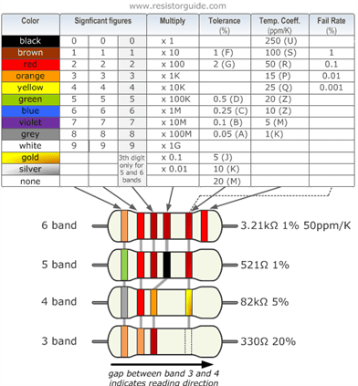
After you’ve determined which resistor you need, the next task is to find it. Fixed-value resistors use colored bands to indicate the value of the resistor. To find the value you can use a multimeter on the ohms (Ω) setting, but if you don’t have a multimeter handy, use the following table to find the value instead. For example,
a resistor with brown, black, brown, and gold bands is a 100Ω resistor with a 5% tolerance.
[source: dummies]
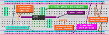
WHAT IS A BREADBOARD?
A breadboard is a solderless construction base used for developing an electronic circuit and wiring for projects with microcontroller boards like Arduino. A breadboard consists of two areas called strips, and are often separated from the middle portion (commonly known as ravine). Bus strips are mainly used for power supply connections Terminal strips are mainly used for electrical components Each strip consist of 5 pinholes, indicating that you only can connect up to 5 components in one particular section. [source: seeedstudio]
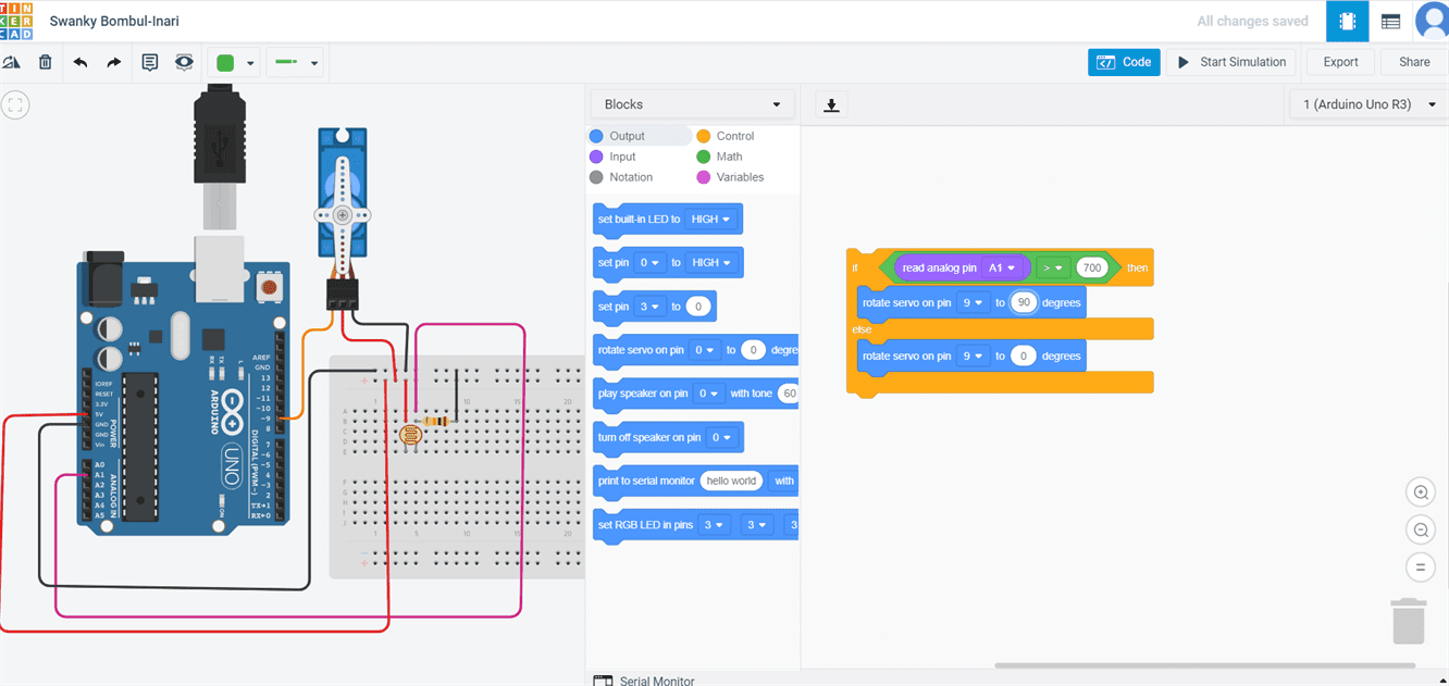
SCHEMATIC DIAGRAM AND CODING ON TINKERCAD
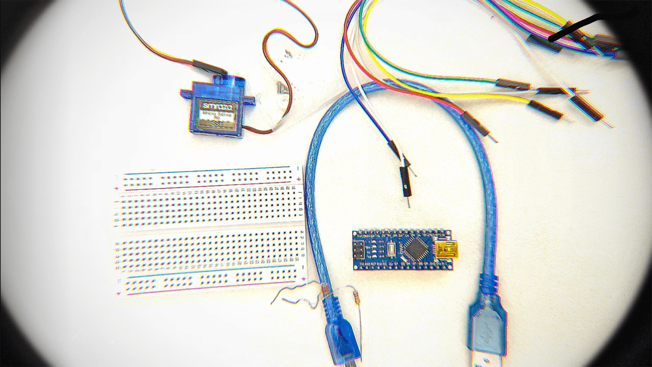
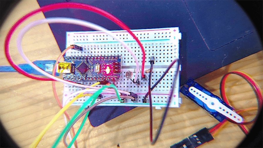
FINAL BOARD SETUP AND ARDUINO IDE PROGRAM
The following materials were used:
1. Arduino Nano
2. Micro USB Cable
3. Breadboard
4. Jumper Wires
5. Resistor - 10k Ohms
6. Servo Motor
7. Photoresistor
The final board setup was done exactly like the above set up on Tinkercad.
After setting up the board I copy pasted the C code from Tinkercad to Arduino IDE and
uploaded it to test my circuit.
The light value was changed to 500 as per the light in the room I was working at.
Below is the final code:
[Note: In the first line #include, there is no space inside brackets
on left/right of servo.h, only added because otherwise .h hides the word on the site]
#include < Servo.h >;

Servo servo_9;


void setup()

{

  pinMode(A1, INPUT);

  servo_9.attach(9, 500, 2500);

}


void loop()

{

  if (analogRead(A1) > 500) {

    servo_9.write(90);

  } else {

    servo_9.write(0);

  }

  delay(10); // Delay a little bit to improve simulation performance


}
I did not experience any big problem during
this assignment other than getting lost in the jungle of wires for a minute or two.