2. Computer Aided design
This Weeks’ Task:
1- Model (raster, vector, 2D, 3D, render, animate, simulate, …) compress your images and videos, and post it on your class page.
================================================================================================================
WHAT IS CAD?
Computer Aided Design which essentially is the use of computers to aid in the creation, modification, analysis, or optimization of a design.
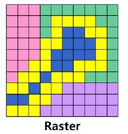
RASTOR GRAPHICS
Raster graphics, also called bitmap graphics, a type of digital image that uses tiny rectangular pixels, or picture elements, arranged in a grid formation to represent an image. Because the format can support a wide range of colours and depict subtle graduated tones, it is well-suited for displaying continuous-tone images such as photographs or shaded drawings, along with other detailed images.
Example
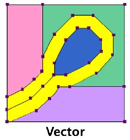
VECTOR GRAPHICS
vector graphics are comprised of paths, which are defined by a start and end point, along with other points, curves, and angles along the way. A path can be a line, a square, a triangle, or a curvy shape. These paths can be used to create simple drawings or complex diagrams. Paths are even used to define the characters of specific typefaces.
=========================================================================================================
We were introduced to some of the softwares that we can be able to create those modifications like vectr , inkscape , cuttle , GIMP for 2D designs and OpenScad , Fusion360, TinkerCad , FreeCad for 3D designs (Technically all 3D softwares can be used for 2d modifications) and the choices are not limited!
The goal for this week was to experiment and explore with as many softwares possible and choose the ones we feel comfortable with!
===========================================================================================================
SOFTWARES I USED
CUTTLE
Cuttle is a browser-based design tool for digital cutting machines like lasercutters, digital die cutters, and CNC routers. Cuttle combines the simplicity and expressiveness of vector editing with the precision and power of parametric CAD.
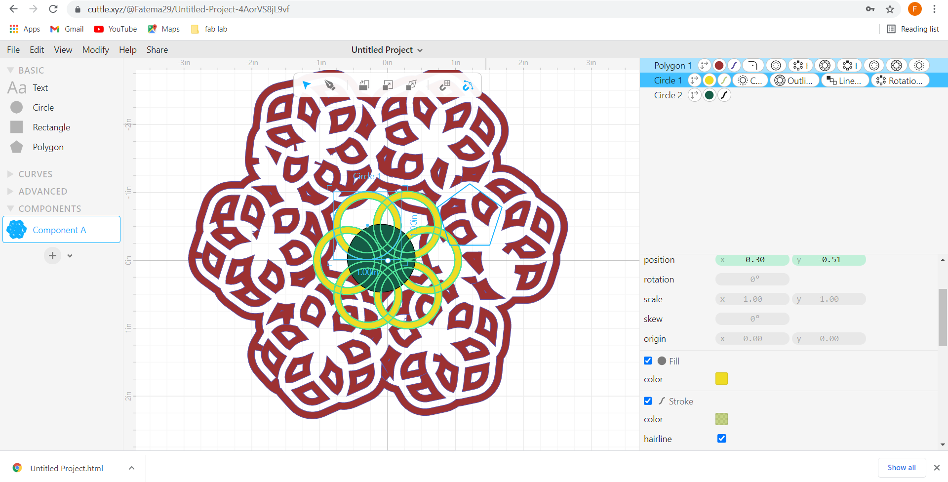
This was my testing work using
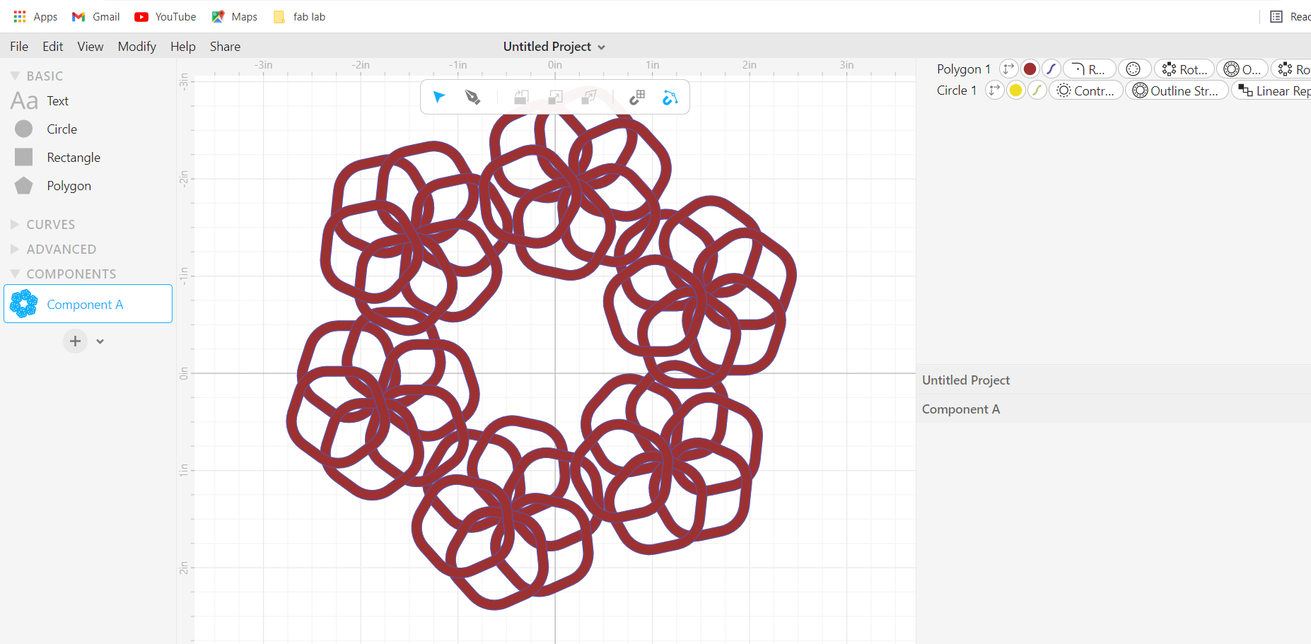
I started by dragging a circle to the canvas and played around with the mesaurments and colours as per desire.
then I started testing the modifying option and used the “outline stroke” to get outline the circle and used the “rotational repeat” twice to achieve a continuous shape.
Here are some of the modifications I also used!

I found cuttle to be intresting and different from the others. I did not quite get the hang of it which I will use it to my advantage to learn about it!
=============================================================================================================================================
INKSCAPE
Inkscape is a Free and open source vector graphics editor for GNU/Linux, Windows and MacOS X. It offers a rich set of features and is widely used for both artistic and technical illustrations such as cartoons, clip art, logos, typography, diagramming and flowcharting.
This was my work using
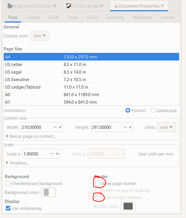
I started by clicking on File then document properties and removing “show boarder shadow” first and “show page boarder”
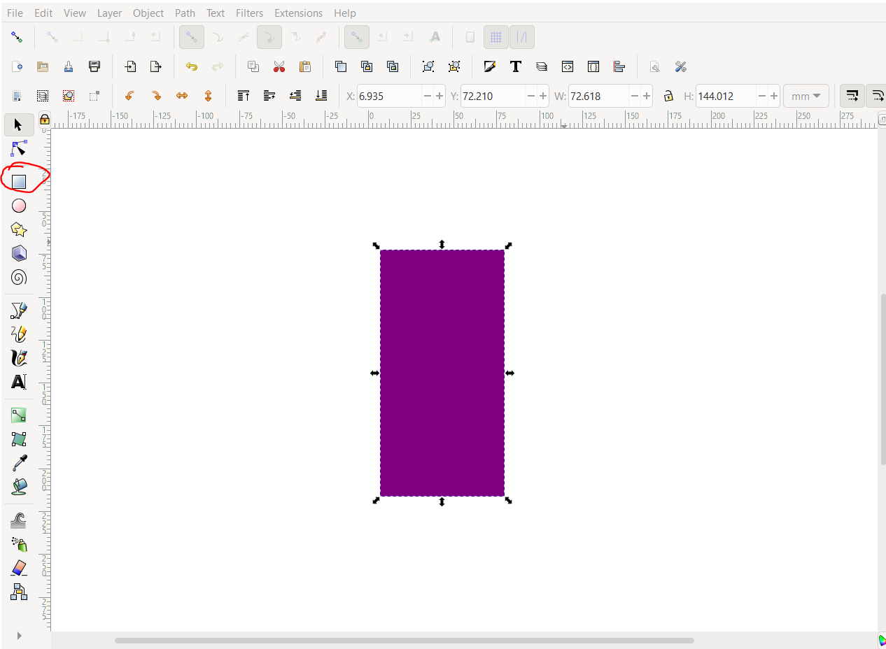
FIRST: I dragged a rectangle to the canvas
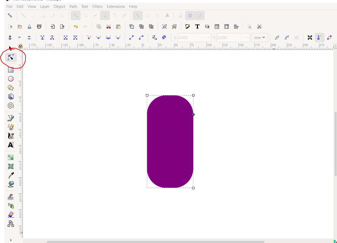
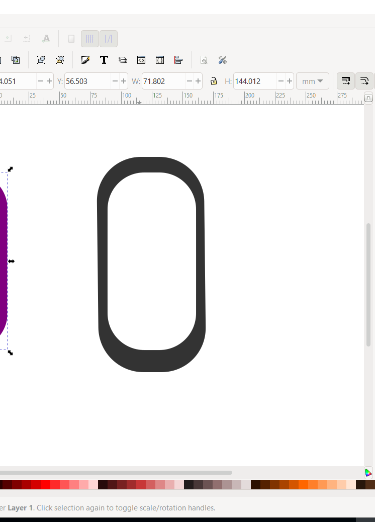
SECOND: I used the “edit paths by nodes” option to round the edges
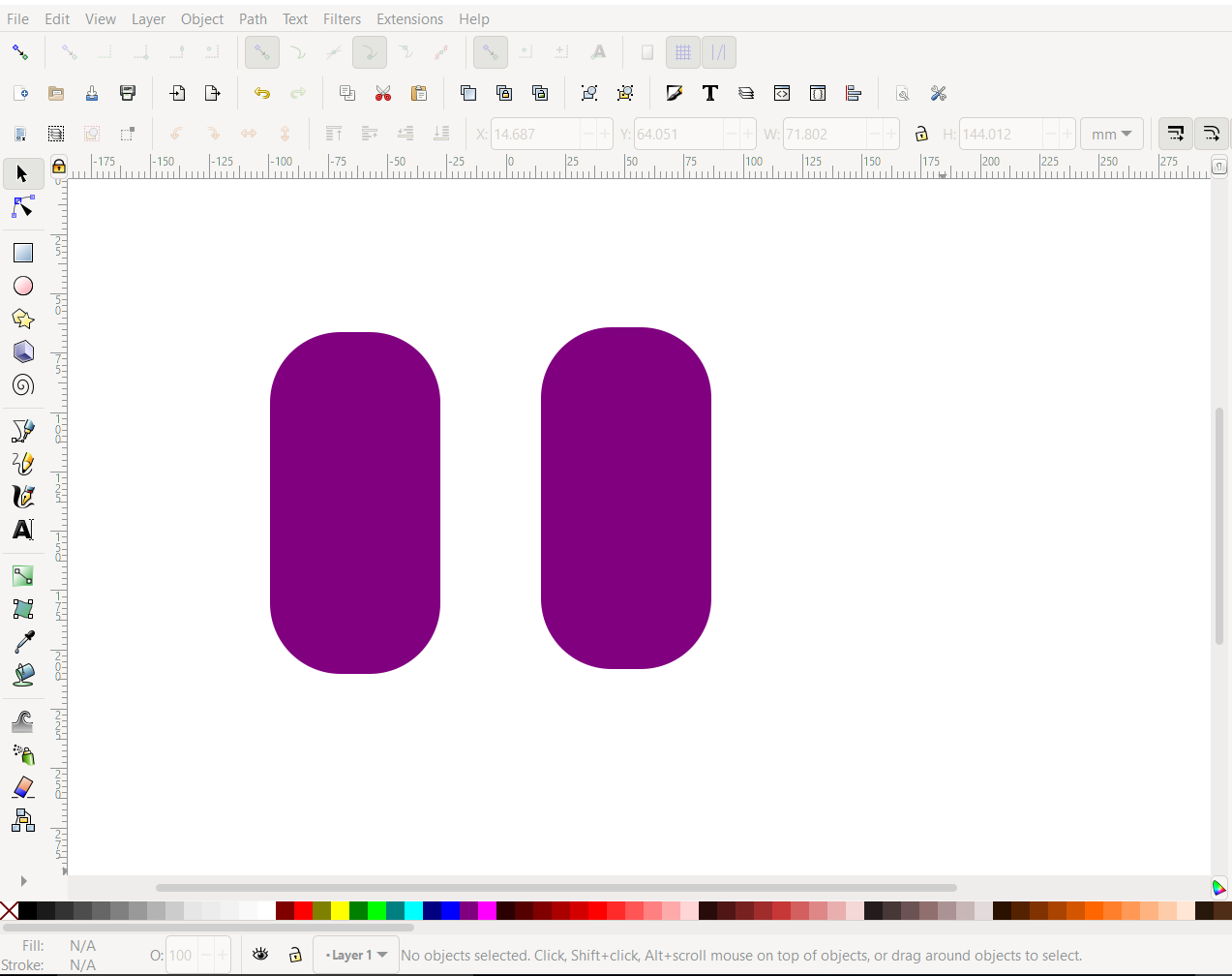
THIRD: I duplicated the project by right clicking and choosing the duplicate option
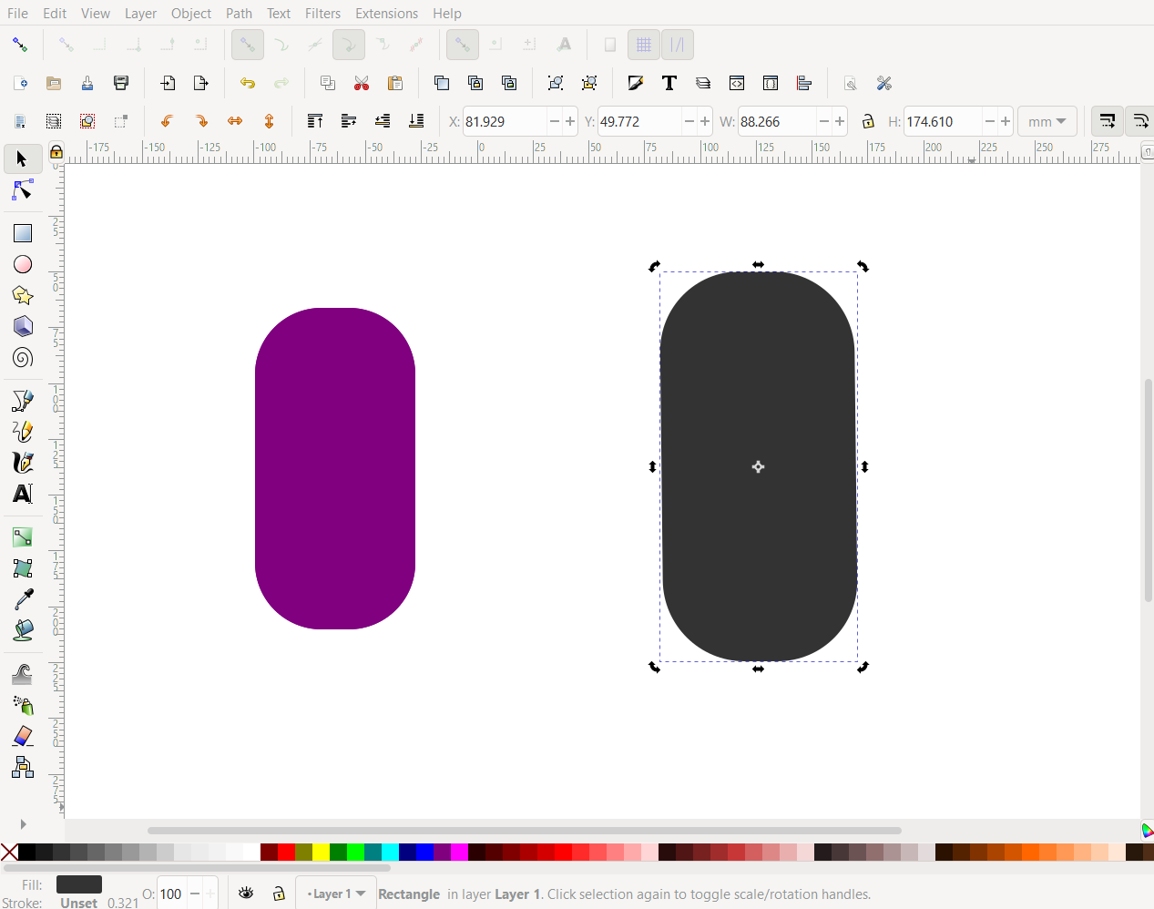
FOURTH: I adjusted the duplicated shape to become bigger than the original and changed the color for a better view
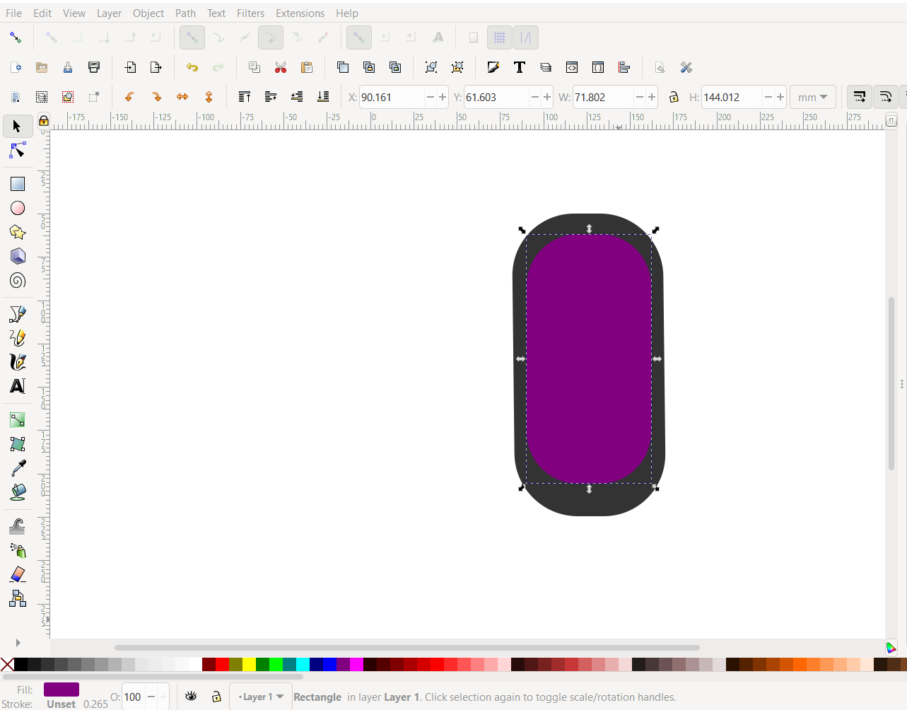
FIFTH: I overlapped the projects
SIXTH: I duplicated the original shape once again
SEVENTH: I selected these two shapes using “Ctrl A”
EIGTH: I clicked on the option “paths” and then “Difference”
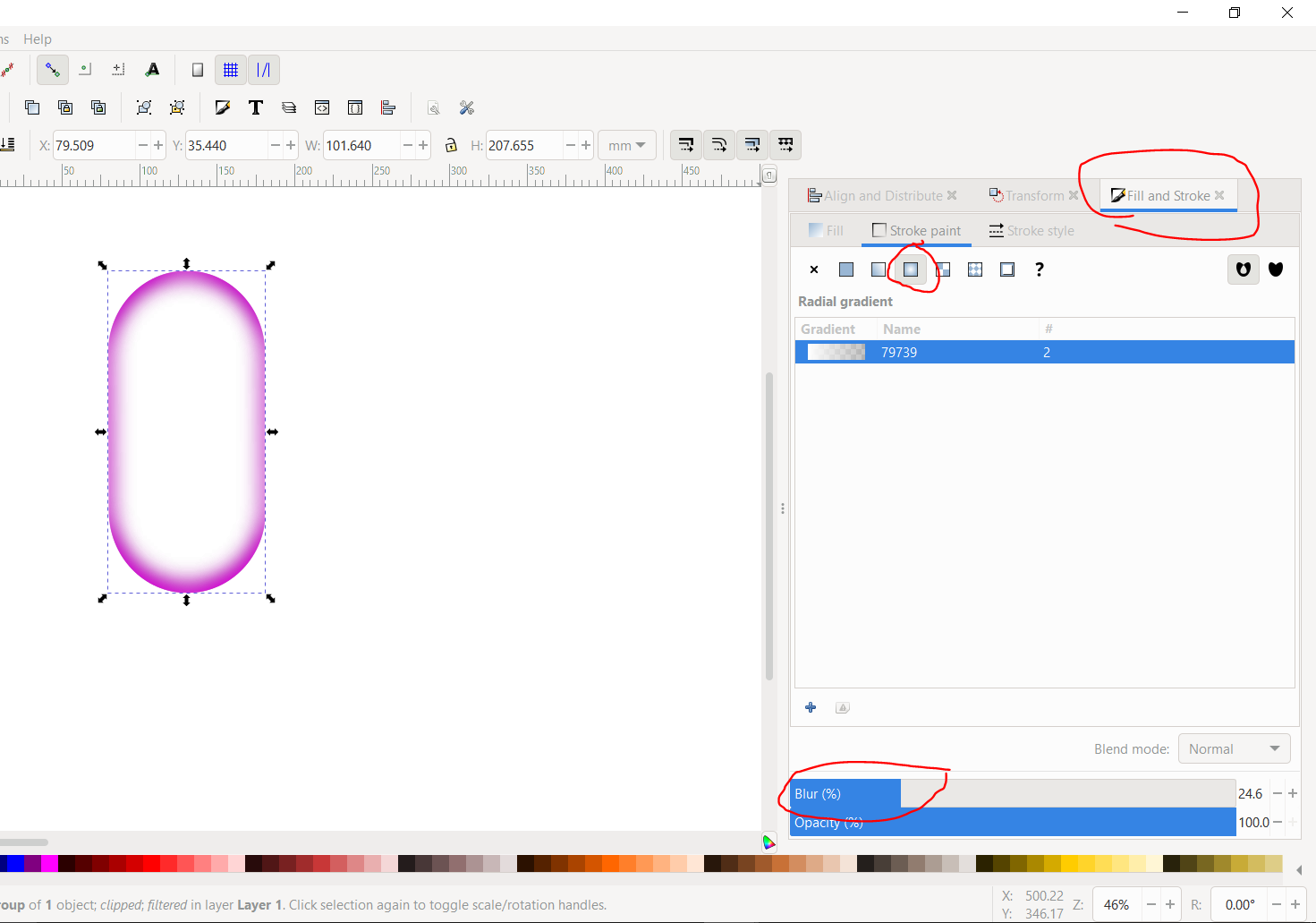
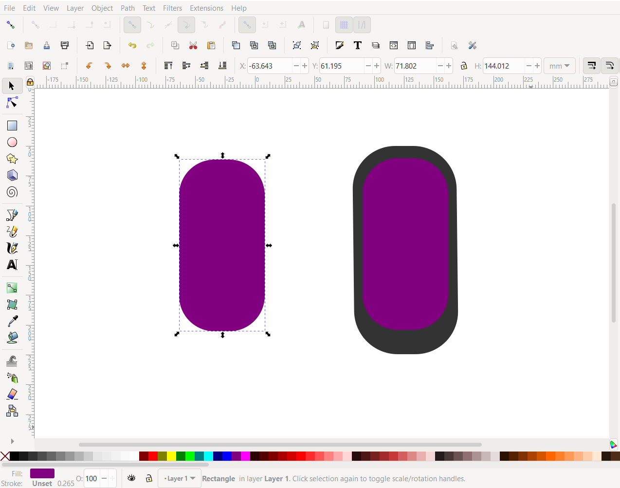
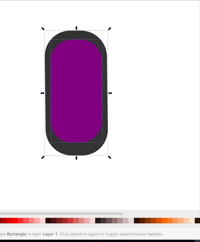
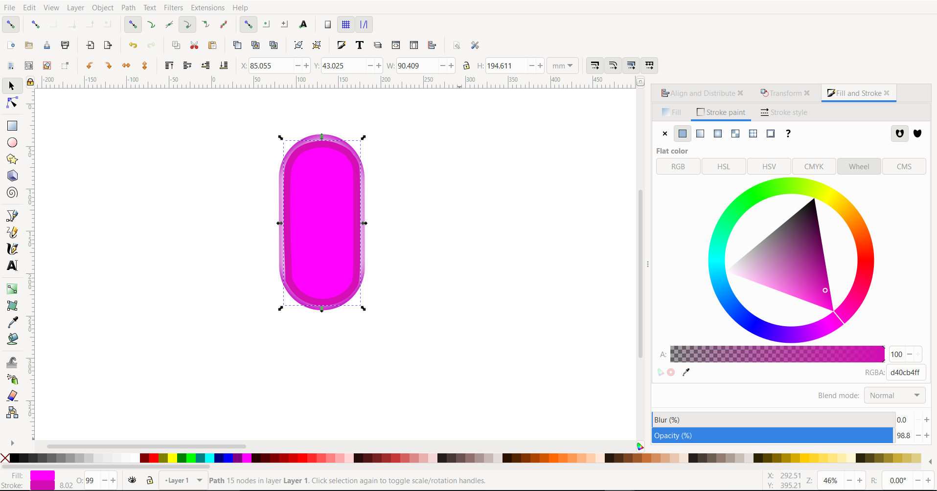
NINTH: I started modifying changes as per desire using the highlighted options
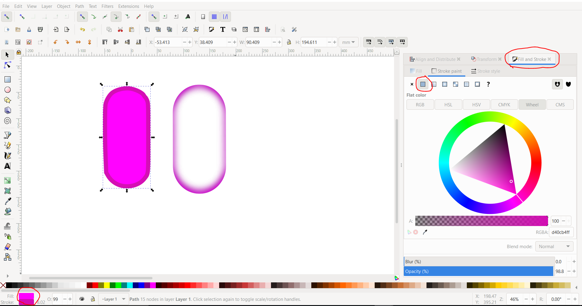
TENTH: I started modifying changes to the other shape we duplicated earlier once again as per desire, I used the highlighted options
ELVENTH: I overlapped the shapes to give an effect and used the text option to write down my prefered text and used the circle option to create a hole in where the chain can be attached
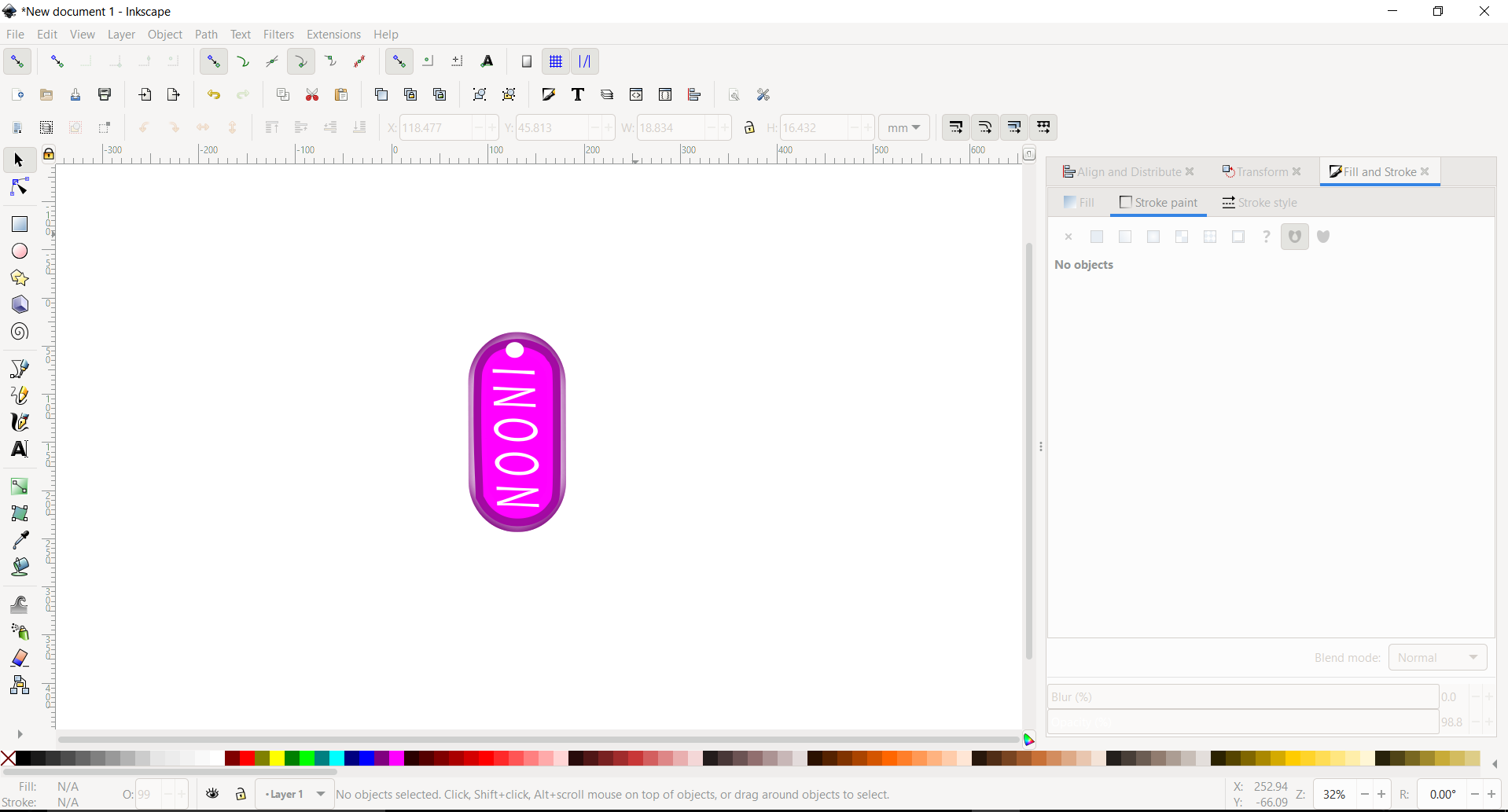
And this is the final keychain result!

===========================================================================================================================================
FUSION 360
Fusion 360 is a cloud-based CAD/CAM tool for collaborative product development. Fusion 360 enables exploration and iteration on product ideas and collaboration within distributed product development team. Fusion 360 combines organic shapes modelling, mechanical design and manufacturing in one comprehensive package.

Firstly I created a new sketch on the top plane and drew a circumscribed polygon with number of sides as 12 and diameter as 5 and click on “Finish Sketch”
Secondly I extruded the profile downward at an angle of -45.5 degree and dragged it until I got a sharp edge, Next I extruded the upper surface at an angle of -5 degree up to a distance of 0.15cm.
Thirdly Extrude the upper surface again at an angle of -50.5 degree up to a distance of 1.25cm, here the shape should start appearing
Fourthly I clicked on construct and on the option of “plane through 3 points” and selected the 3 points on the edge to form a triangle
Fifthly After that, I clicked on the option “create a sketch” and on the option “line” and drew a triangle on the same spot
sixthly I extruded the profile to cut a sharp edge.
seventhly I clicked on “create” and on the option pattern and then choose “circular pattern”
Eightly For the pattern type I selected “features” and selected the previous cut as the object and then I selected the green line as the axis of the pattern and number of objects as 6. Here we have finished designing the shape!
Ninethly I clicked on “A” from the keyboard to open the appearance option, clicked on glass then smooth and selected the glass(blue) option.
Lastly I did a little adjustment with the color according to my liking and viola!
Refer to this tutorial for a better understanding
==========================================================================================================================================
OPENSCAD
OpenSCAD allows to describe 3D objects as code, which can be organized in libraries and reused in various contexts. It provides an editor with an interactive 3D object view, allowing to quickly understand how the code translates to 3D geometries and refine and debug the model.
The great advantage of OpenSCAD is that the designs can be parametrized and adjusted to suit varying needs or to refine a design through successive prototyping cycles.
This is my work using
Here’s what I created using this drawing as a reference
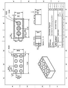
And this tutorial as a guide

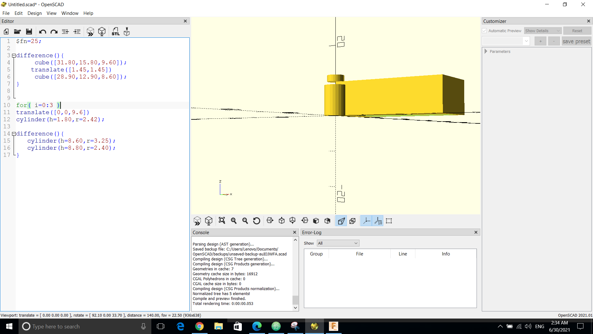
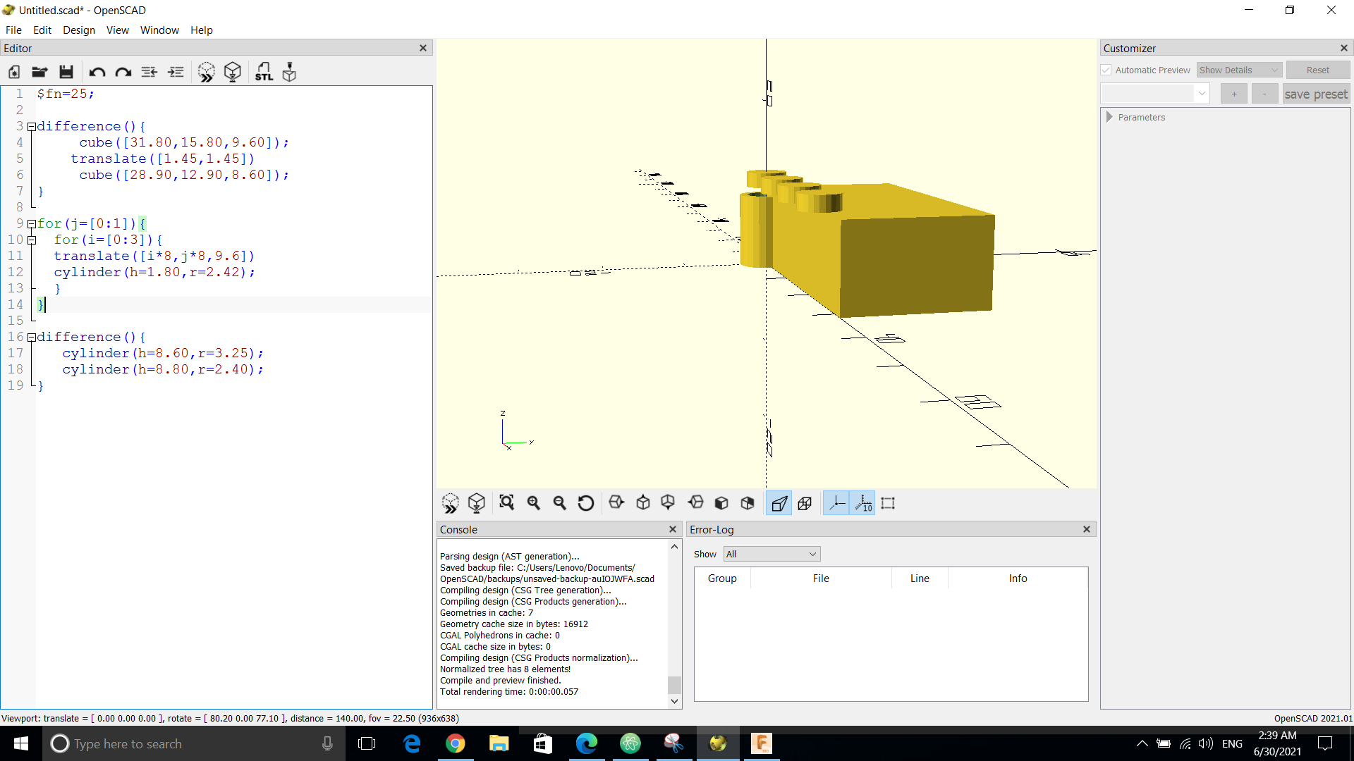
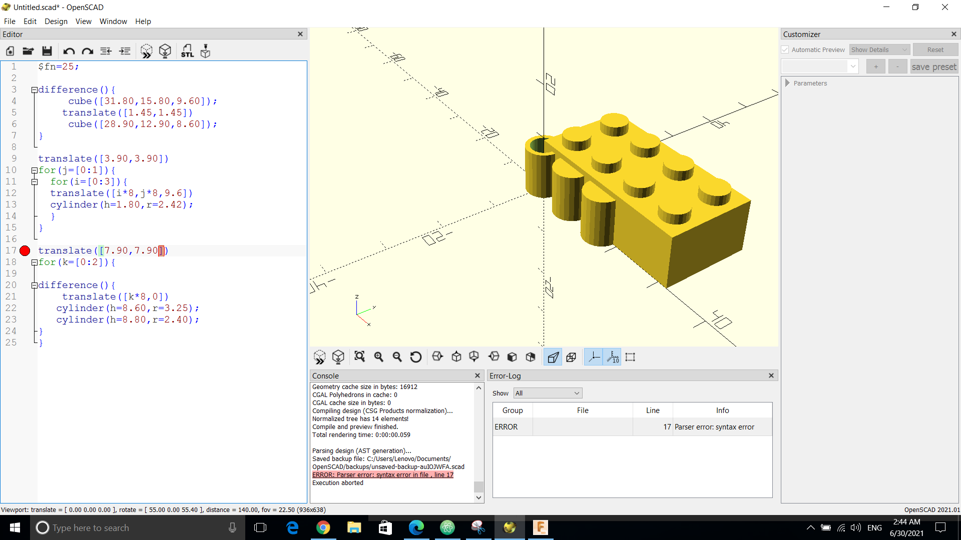
**Here I faced an error which OpenSCAD highlighted it which made it very easy to fix
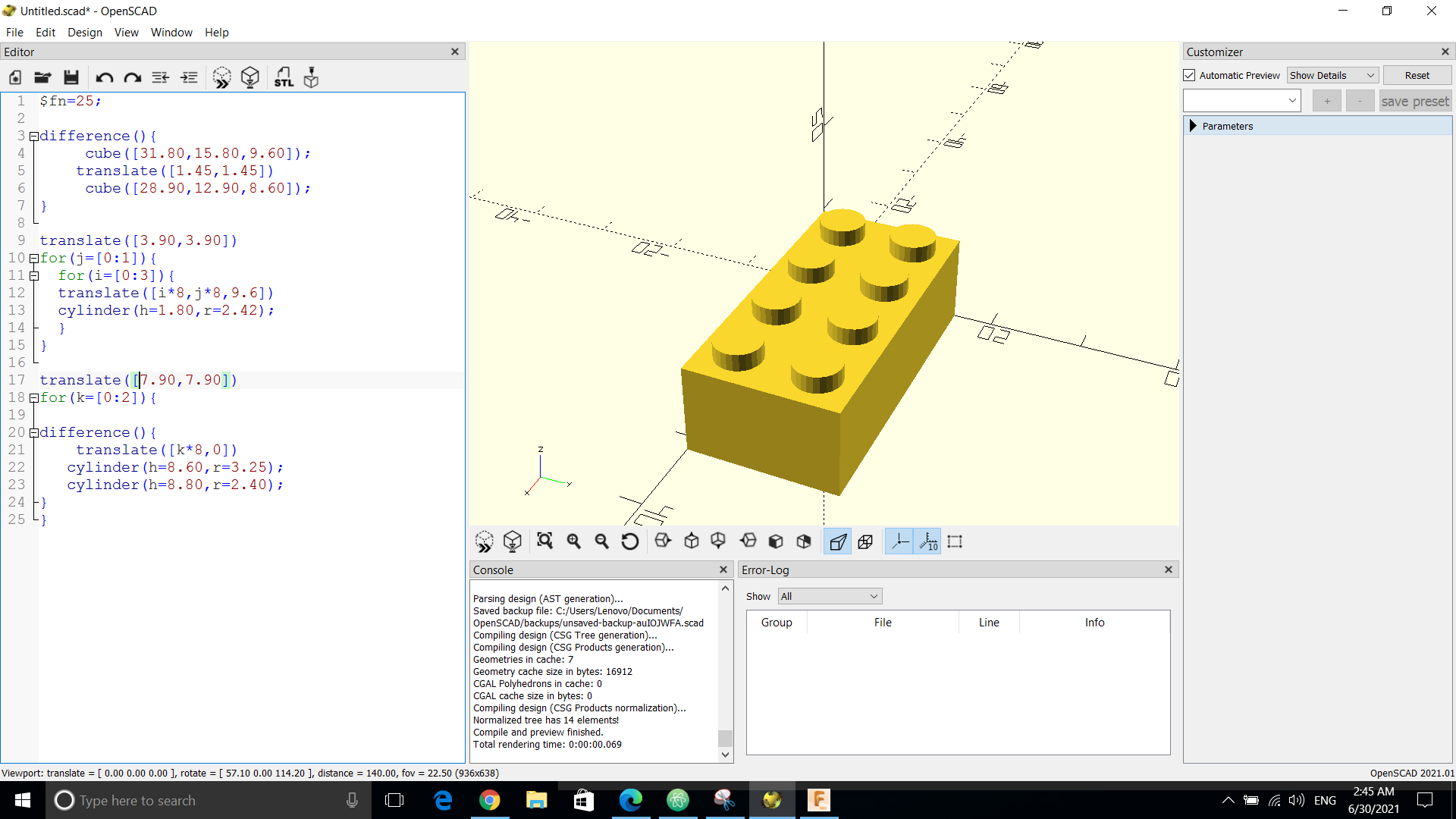
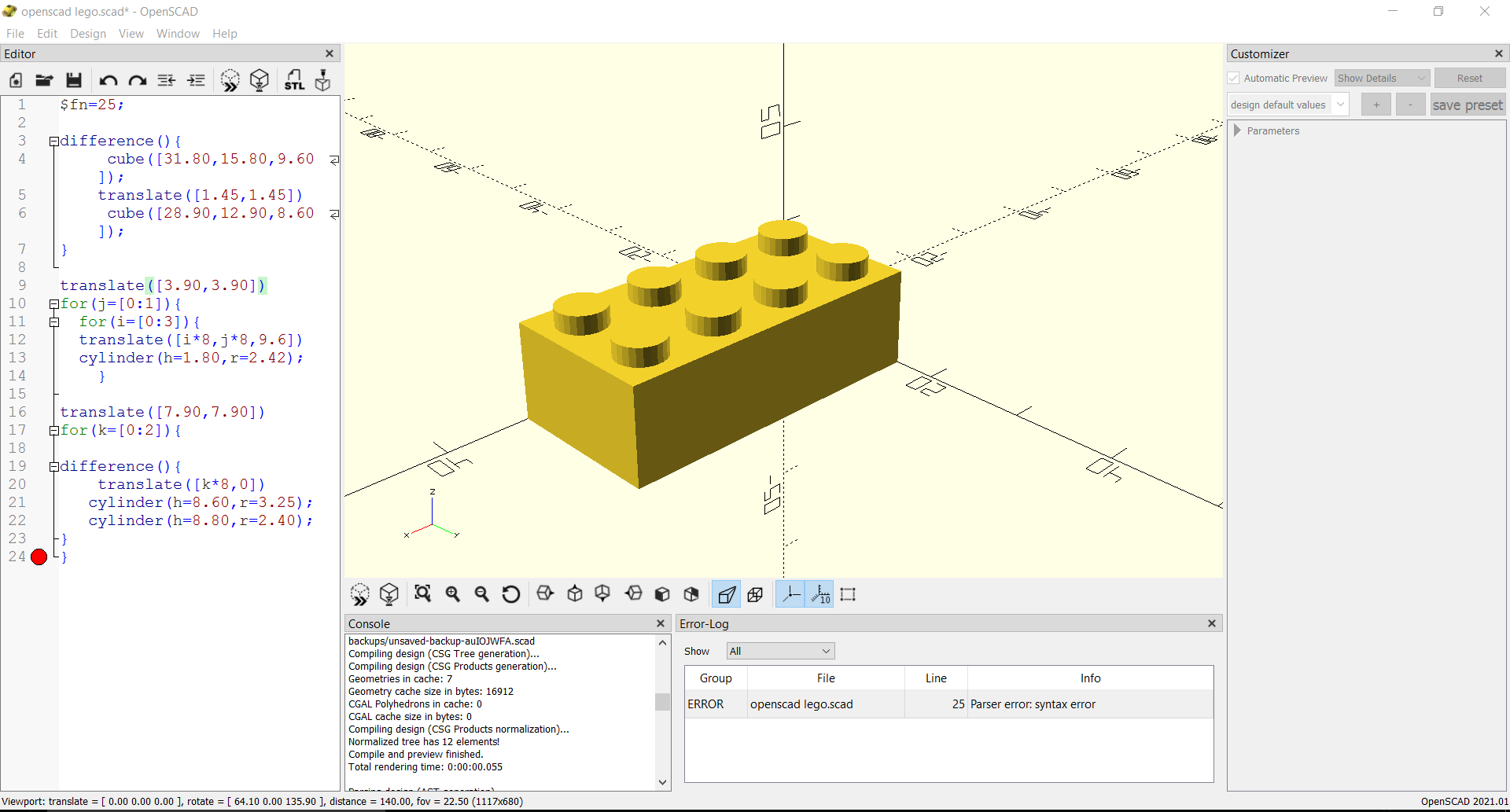
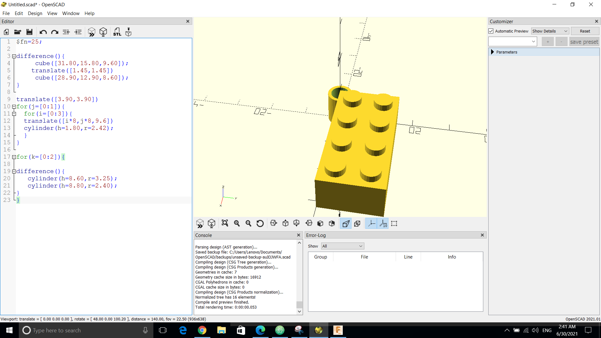
And this is the final result!!!
OPENSCAD CHEATSHEET
DOWNLOADABLE FILES
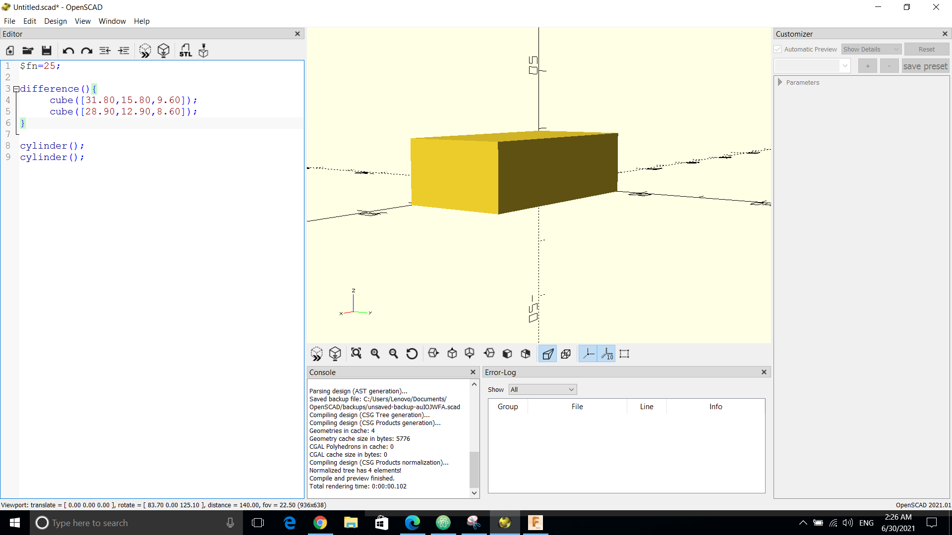
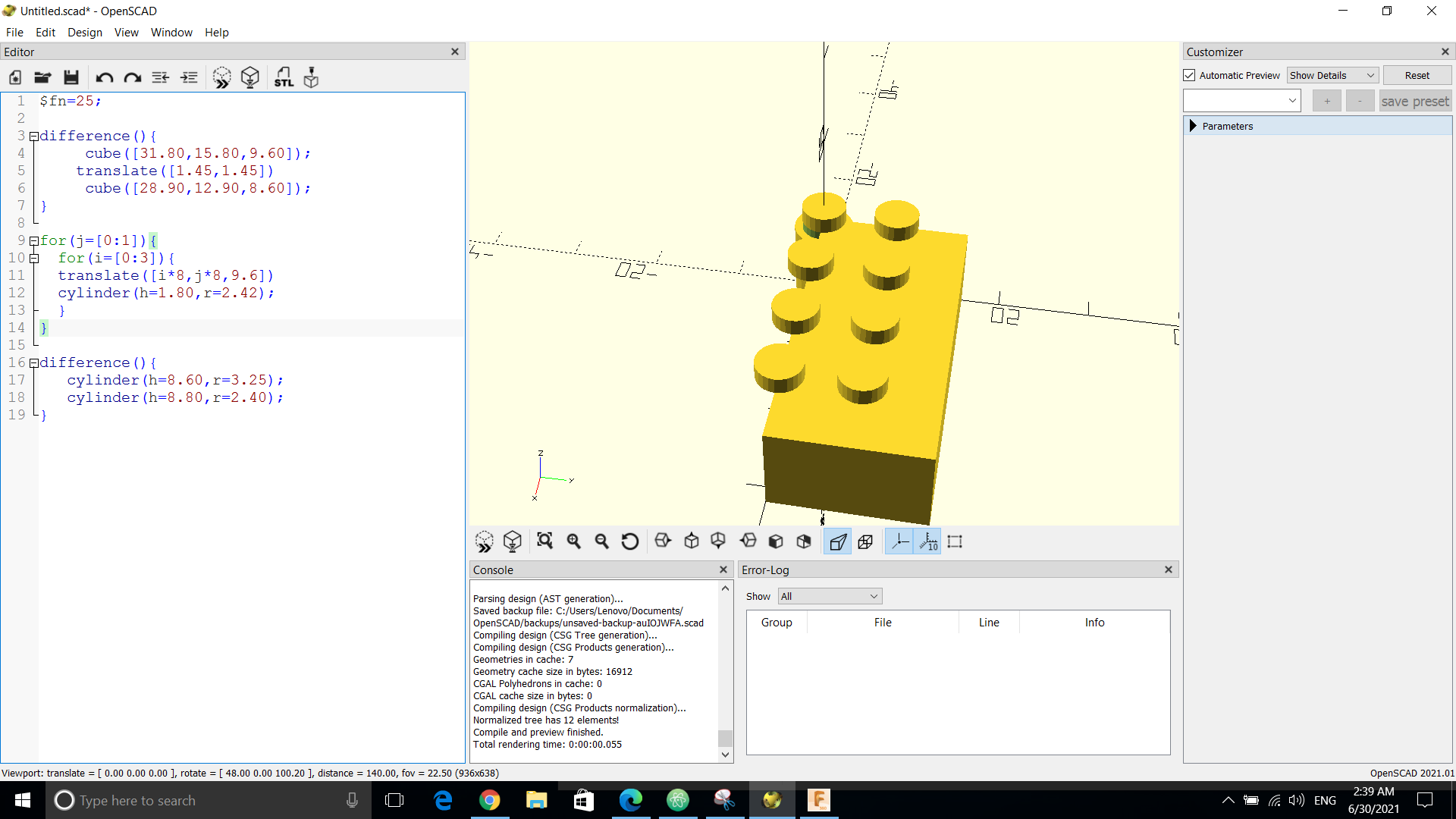
$fn=25;
difference(){ cube([31.80,15.80,9.60]); translate([1.45,1.45]) cube([28.90,12.90,8.60]); }
translate([3.90,3.90]) for(j=[0:1]){ for(i=[0:3]){ translate([i8,j8,9.6]) cylinder(h=1.80,r=2.42); } }
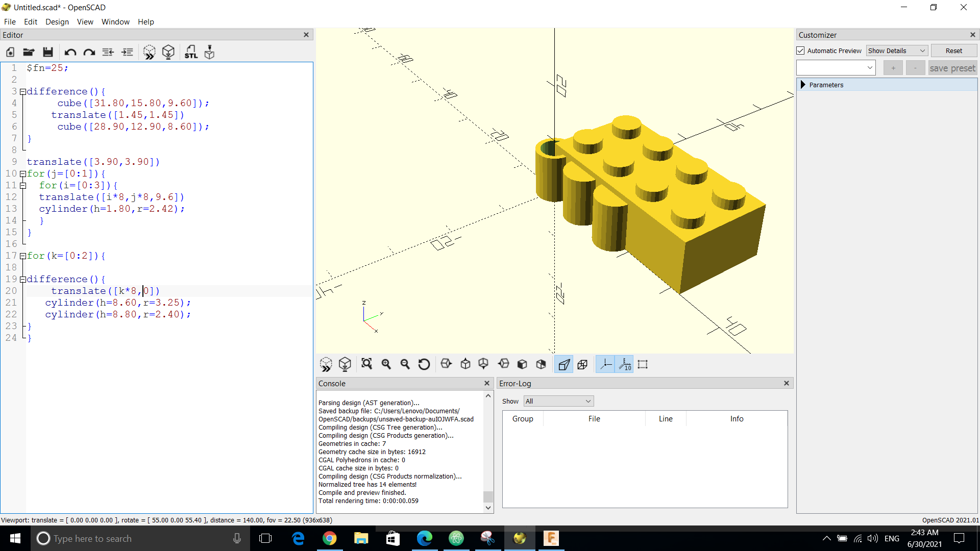
translate([7.90,7.90]) for(k=[0:2]){
difference(){ translate([k*8,0]) cylinder(h=8.60,r=3.25); cylinder(h=8.80,r=2.40); } }
=============================================================================================================================================
Personal experience
I found this week very fun yet challenging as I’ve never came across these softwares or creating a computer aided design and this week really helped me to understand the basics using different techniques and softwares that can be really be useful!