8. Input/Output devices
This week tasks
Measure something: add a sensor to a microcontroller board and read it. Add an output device to a microcontroller board and program it to do something.
===========================================================================================
Input
what is put in, taken in, or operated on by any process or system.
Examples of input devices include keyboards, mice, scanners, digital cameras and joysticks.
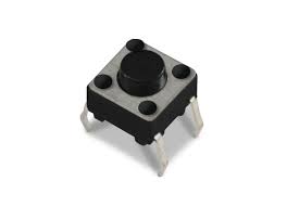
BUTTON
A button is a physical switch that controls a device’s function , it acts as an input when you press and unpress to perform a specific task , this means you can nest elements within a button.
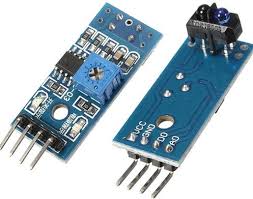
Analog sensor
LDR sensor module is used to detect the intensity of light. It is associated with both analog output pin and digital output pin labelled as AO and DO respectively on the board. When there is light, the resistance of LDR will become low according to the intensity of light. The greater the intensity of light, the lower the resistance of LDR. The sensor has a potentiometer knob that can be adjusted to change the sensitivity of LDR towards light.
===================================================================================
Output
Any information that is processed by and sent out from a computer or other electronic device is considered output.
There are four basic types of output: audio output, graphics output, text output, and video output.
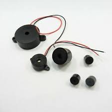
BUZZER
The buzzer consists of an outside case with two pins to attach it to power and ground. … When current is applied to the buzzer it causes the ceramic disk to contract or expand. Changing the This then causes the surrounding disc to vibrate. That’s the sound that you hear.
The buzzer takes the electricity and turns it to sound.
it produces sounds and melody by generating the plate inside the buzzer to vibrate hence, create the sounds.
by giving it different signals, it will vibrate differently to create different sounds.
You can make sounds with a buzzer using the function tone(). In order to use it, you need only to tell the pin to which the buzzer is connected and which frequency
tone(pin, frequency, duration)
Here’s my take on it.....


After trying out the built in example , I wanted to modify it a little to play a song so I used
THE CODE
*/

#define NOTE_B0  31
#define NOTE_C1  33
#define NOTE_CS1 35
#define NOTE_D1  37
#define NOTE_DS1 39
#define NOTE_E1  41
#define NOTE_F1  44
#define NOTE_FS1 46
#define NOTE_G1  49
#define NOTE_GS1 52
#define NOTE_A1  55
#define NOTE_AS1 58
#define NOTE_B1  62
#define NOTE_C2  65
#define NOTE_CS2 69
#define NOTE_D2  73
#define NOTE_DS2 78
#define NOTE_E2  82
#define NOTE_F2  87
#define NOTE_FS2 93
#define NOTE_G2  98
#define NOTE_GS2 104
#define NOTE_A2  110
#define NOTE_AS2 117
#define NOTE_B2  123
#define NOTE_C3  131
#define NOTE_CS3 139
#define NOTE_D3  147
#define NOTE_DS3 156
#define NOTE_E3  165
#define NOTE_F3  175
#define NOTE_FS3 185
#define NOTE_G3  196
#define NOTE_GS3 208
#define NOTE_A3  220
#define NOTE_AS3 233
#define NOTE_B3  247
#define NOTE_C4  262
#define NOTE_CS4 277
#define NOTE_D4  294
#define NOTE_DS4 311
#define NOTE_E4  330
#define NOTE_F4  349
#define NOTE_FS4 370
#define NOTE_G4  392
#define NOTE_GS4 415
#define NOTE_A4  440
#define NOTE_AS4 466
#define NOTE_B4  494
#define NOTE_C5  523
#define NOTE_CS5 554
#define NOTE_D5  587
#define NOTE_DS5 622
#define NOTE_E5  659
#define NOTE_F5  698
#define NOTE_FS5 740
#define NOTE_G5  784
#define NOTE_GS5 831
#define NOTE_A5  880
#define NOTE_AS5 932
#define NOTE_B5  988
#define NOTE_C6  1047
#define NOTE_CS6 1109
#define NOTE_D6  1175
#define NOTE_DS6 1245
#define NOTE_E6  1319
#define NOTE_F6  1397
#define NOTE_FS6 1480
#define NOTE_G6  1568
#define NOTE_GS6 1661
#define NOTE_A6  1760
#define NOTE_AS6 1865
#define NOTE_B6  1976
#define NOTE_C7  2093
#define NOTE_CS7 2217
#define NOTE_D7  2349
#define NOTE_DS7 2489
#define NOTE_E7  2637
#define NOTE_F7  2794
#define NOTE_FS7 2960
#define NOTE_G7  3136
#define NOTE_GS7 3322
#define NOTE_A7  3520
#define NOTE_AS7 3729
#define NOTE_B7  3951
#define NOTE_C8  4186
#define NOTE_CS8 4435
#define NOTE_D8  4699
#define NOTE_DS8 4978
#define REST 0

// change this to make the song slower or faster
int tempo=114;

// change this to whichever pin you want to use
int buzzer = 11;

// notes of the moledy followed by the duration.
// a 4 means a quarter note, 8 an eighteenth , 16 sixteenth, so on
// !!negative numbers are used to represent dotted notes,
// so -4 means a dotted quarter note, that is, a quarter plus an eighteenth!!
int melody[] = {


  NOTE_E4,4,  NOTE_E4,4,  NOTE_F4,4,  NOTE_G4,4,//1
  NOTE_G4,4,  NOTE_F4,4,  NOTE_E4,4,  NOTE_D4,4,
  NOTE_C4,4,  NOTE_C4,4,  NOTE_D4,4,  NOTE_E4,4,
  NOTE_E4,-4, NOTE_D4,8,  NOTE_D4,2,

  NOTE_E4,4,  NOTE_E4,4,  NOTE_F4,4,  NOTE_G4,4,//4
  NOTE_G4,4,  NOTE_F4,4,  NOTE_E4,4,  NOTE_D4,4,
  NOTE_C4,4,  NOTE_C4,4,  NOTE_D4,4,  NOTE_E4,4,
  NOTE_D4,-4,  NOTE_C4,8,  NOTE_C4,2,

  NOTE_D4,4,  NOTE_D4,4,  NOTE_E4,4,  NOTE_C4,4,//8
  NOTE_D4,4,  NOTE_E4,8,  NOTE_F4,8,  NOTE_E4,4, NOTE_C4,4,
  NOTE_D4,4,  NOTE_E4,8,  NOTE_F4,8,  NOTE_E4,4, NOTE_D4,4,
  NOTE_C4,4,  NOTE_D4,4,  NOTE_G3,2,

  NOTE_E4,4,  NOTE_E4,4,  NOTE_F4,4,  NOTE_G4,4,//12
  NOTE_G4,4,  NOTE_F4,4,  NOTE_E4,4,  NOTE_D4,4,
  NOTE_C4,4,  NOTE_C4,4,  NOTE_D4,4,  NOTE_E4,4,
  NOTE_D4,-4,  NOTE_C4,8,  NOTE_C4,2

};

// sizeof gives the number of bytes, each int value is composed of two bytes (16 bits)
// there are two values per note (pitch and duration), so for each note there are four bytes
int notes=sizeof(melody)/sizeof(melody[0])/2;

// this calculates the duration of a whole note in ms (60s/tempo)*4 beats
int wholenote = (60000 * 4) / tempo;

int divider = 0, noteDuration = 0;

void setup() {

  // iterate over the notes of the melody.
  // Remember, the array is twice the number of notes (notes + durations)
  for (int thisNote = 0; thisNote < notes * 2; thisNote = thisNote + 2) {

    // calculates the duration of each note
    divider = melody[thisNote + 1];
    if (divider > 0) {
      // regular note, just proceed
      noteDuration = (wholenote) / divider;
    } else if (divider < 0) {
      // dotted notes are represented with negative durations!!
      noteDuration = (wholenote) / abs(divider);
      noteDuration *= 1.5; // increases the duration in half for dotted notes
    }

    // we only play the note for 90% of the duration, leaving 10% as a pause
    tone(buzzer, melody[thisNote], noteDuration*0.9);

    // Wait for the specief duration before playing the next note.
    delay(noteDuration);

    // stop the waveform generation before the next note.
    noTone(buzzer);
  }

}

void loop() {
  // if you want to repeat the song forever,
  // just paste the setup code here instead.
}
And here’s the result !
.
=========================================================================================
BUTTON AND SERVO MONITOR
.
I defined the servo pin to 6,Then defined the push button pin to 3 .
Next defining the initial angle of the motor, I used 90* .
The initial angle step = the value will increment from initial angle by 10. .
Then defining the minimum and maximum angles of the motors (0,180). .
THE CODE
#include <Servo.h>

Servo myservo;
#define servoPin 6
#define pushButtonPin 2

int angle =90;    // initial angle  for servo (between 1 and 179)
int angleStep =10;
const int minAngle = 0;
const int maxAngle = 180;

const int type =2;

int buttonPushed =0;

void setup() {
  Serial.begin(9600);
  myservo.attach(servoPin);
  pinMode(pushButtonPin,INPUT_PULLUP);
   Serial.println(" Servo Button ");
   myservo.write(angle);//initial position
}

void loop() {
  if(digitalRead(pushButtonPin) == LOW){
    buttonPushed = 1;
  }
   if( buttonPushed ){
  // change the angle for next time through the loop:
  angle = angle + angleStep;

    // reverse the direction of the moving at the ends of the angle:
    if (angle >= maxAngle) {
      angleStep = -angleStep;
        if(type ==1)
        {
            buttonPushed =0;
        }
    }

    if (angle <= minAngle) {
      angleStep = -angleStep;
       if(type ==2)
        {
            buttonPushed =0;
        }
    }

    myservo.write(angle); // move the servo to desired angle
      Serial.print("Moved to: ");
      Serial.print(angle);   // print the angle
      Serial.println(" degree");
  delay(100); // waits for the servo to get there
   }


}
Here’s the result
.
======================================================================================
ANALOG SENSOR AND SERVO MOTOR
I defined the sensor pin by A0.
Then defined the servo motor by D9.
Next in the void setup() I set up the pin mode to sensor pin as an input.
Next I defined the value, if the value is 0 which is white or nothing in front of the sensor, the motor will not move , if the value is 1 which is black or something in front of the sensor, the motor will move to 90 degrees.
THE CODE
#include
Servo tap_servo;
int sensor_pin = A0;
int tap_servo_pin =9;
int val;
void setup () {
pinMode (sensor_pin, INPUT);
tap_servo.attach(tap_servo_pin);
}
void loop (){
val = digitalRead (sensor_pin);
// black
if (val == 0)
{tap_servo.write(0);
}
if (val == 1)
{tap_servo.write(180);
}
}
Here’s the result