Since the first week in Fablab, I was thinking of my final project everyday and had more than one idea. But the main thing,
I wanted to do something that is related to my major, which is mechanical engineering, to use my knowledge and practice
something that I like.
I ended up with the idea of improving the Mechanical Iris I did earlier in Computer-Controlled Machining (Week #6).
Where the result I had was not perfect, because of the high friction that made the movement of the iris really difficult.
I thought of using another material to reduce the friction, and add electronics to open and close the iris automatically using a sensor input.
This project is meant to be used as a skylight, so that when the iris is fully opened it will allow the entering of sun light.
I was inspired by this idea from a website called MAKE, where Caleb Kraft Buitl a giant iris skylight.
He explained the idea in the video.
For my project I will use the same design I have used in Week #8. It is a small scale and not suitable for skylight, but I will do just a prototype that shows my idea.
Steps to Complete this Project
To ensure a smooth workflow and a good result at the gived deadline, I put a list of the things I should do to complete the project:
Design: Draw the mechanial iris using Fusion360 and have a complete model.
Computer-Controlled Cutting: Using the laser cutter to cut the model.
Assemble: Assembling the parts together to make sure of the iris movement
Microcontroller programming: Using a sensor (input device) and a motor (output device).
Connection an Mechanisim: Thinking of a way to connect the motor movement to the iris and a mechanisim to close it again.
Design and Have a Model
Using Fusion360
I used the same design I did in Week #6, where I followed this tutorial.
This was the result of the mechanical iris.
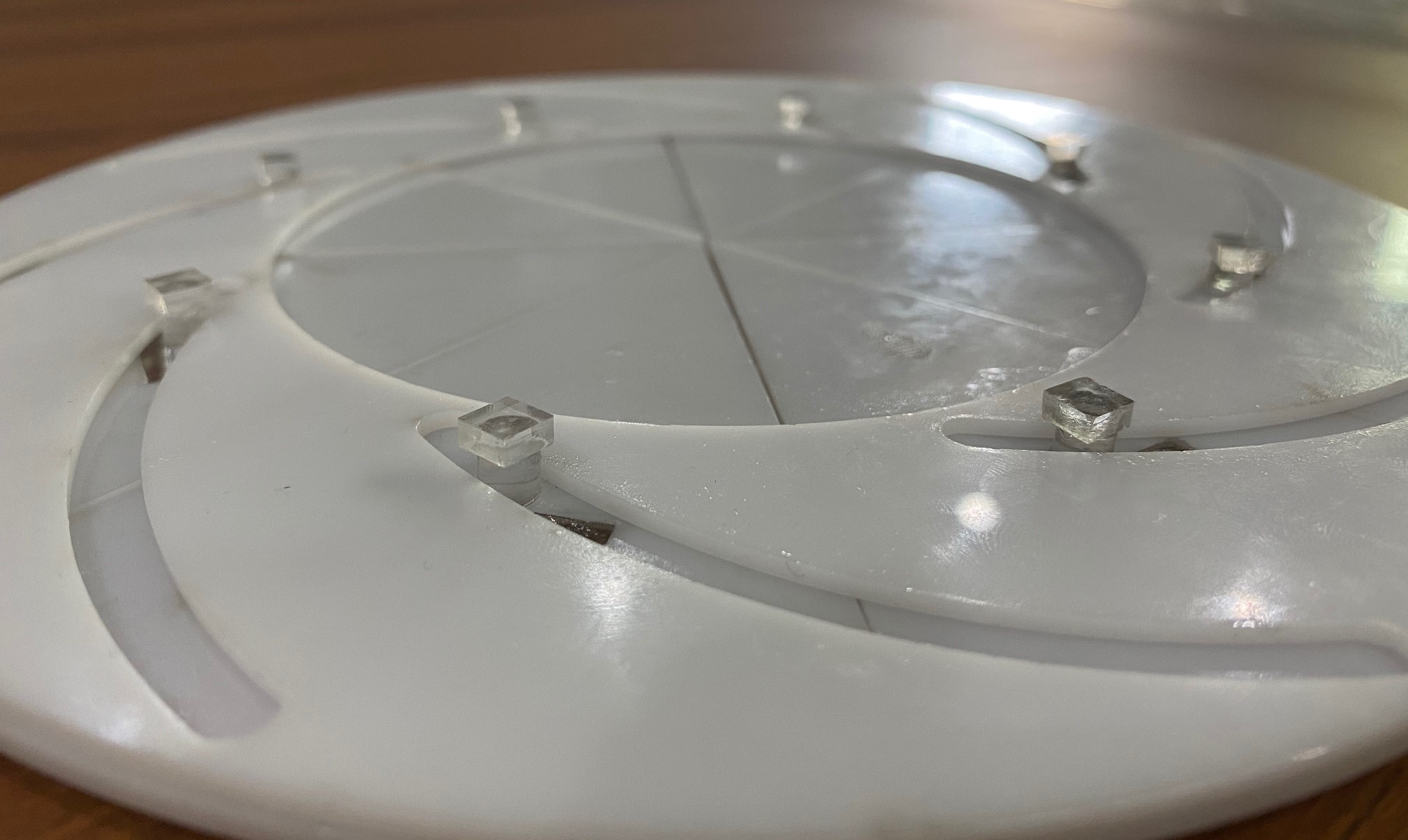
I used the same tringle and the ring that has a handle, but the other ring I changed it a drew it again to enhance my design, and this is how it looked.
Instead of a ring, I did a sequare that is bigger in size, to have a place for the motor and the mechanisim. I also removed
the opening in the middle, because I don't want the skylight to have an openning.
The design is now ready to be cut, I will also cut 8 pins and 8 rectangles using laser cutter to be assembled on on the tringle.
I drew a simple circle with a diameter of 5mm and a rectangle of 20x3 mm using RDWorks, these will be cut using an acrylic of 6 mm in thickness.
Computer-Controlled Machining
Using the Laser Cutter
For this project, I wanted to use acrylic material for all the parts because I think this will solve the friction problem I faced before.
So, I found laser cutting is the most suitable process to cut acrylic.
I explained the steps needed to start laser cutting process in Week #6.
Part
Material
Ring with a handle
White 3 mm acrylic
Tringle
White 3 mm acryli
Squre
Transparent 3 mm acrylic
Pin
Transparent 6 mm acrylic
Rectangle
Transparent 6 mm acrylic
Electronics box
Transparent 3 mm acrylic
Motor place
Transparent 6 mm acrylic
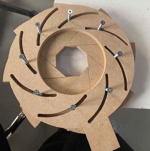
First I started cutting the tringle with the pin and rectangle, to just check if they perfectly fit or not.
After doing that, I printed the rest to have eight tringles. And fixed the pin in each using a glue.
Then I printed the ring that has a handle and fit each tringle to the slots.
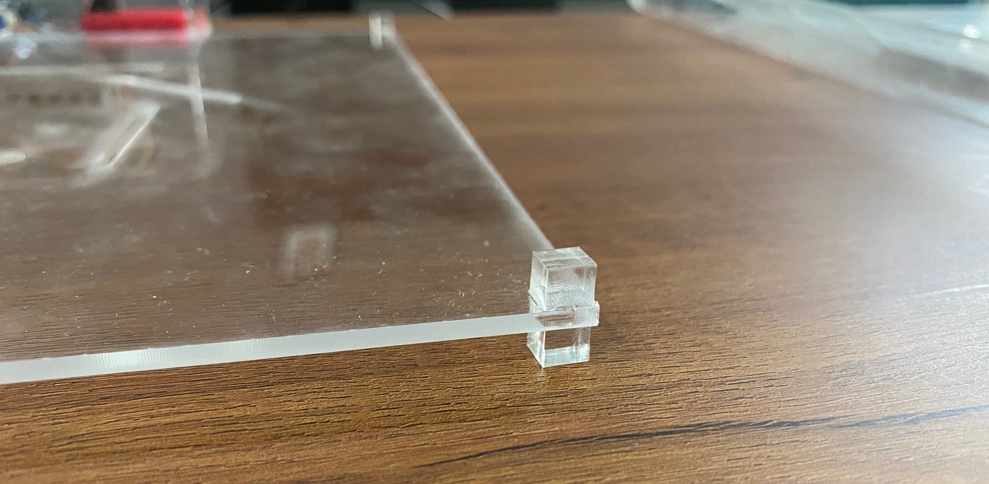
I wanted to ensure that the ring will stay in its place fitted to the tringles. So, I did a small acrylic
square with a round engrave that has the diameter of the pin using the laser cutter. This part is to be sticked
on the pin to hold the ring in its place as the followin.
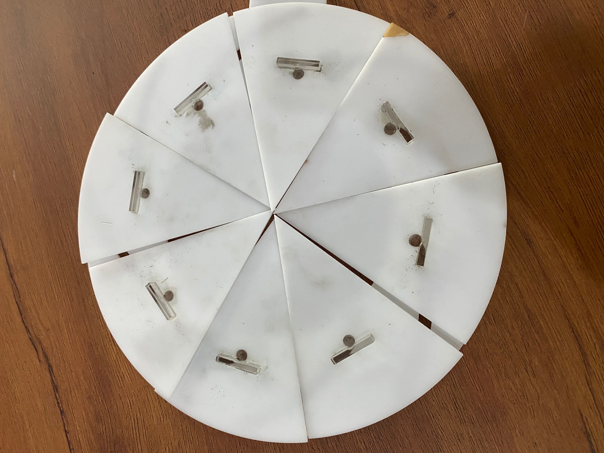
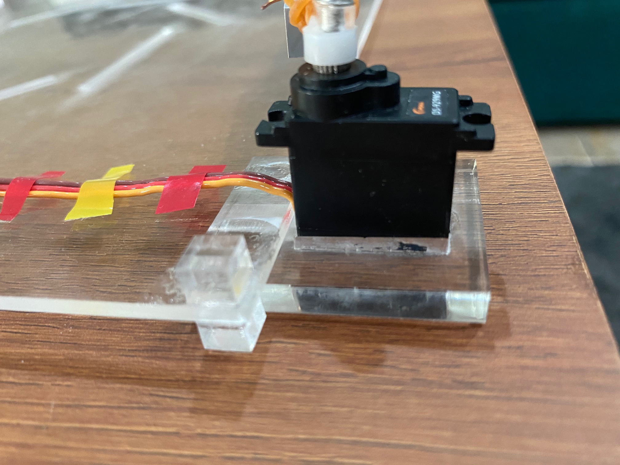
I then did the square part that has slots. I also cut 4 small squares to be fixed in the corners using 6 mm arylic.
This will keep the square 6 mm above the surface to avoid friction.
Then I measured the dimensions of the motor to design an acrylic part that will hold it.
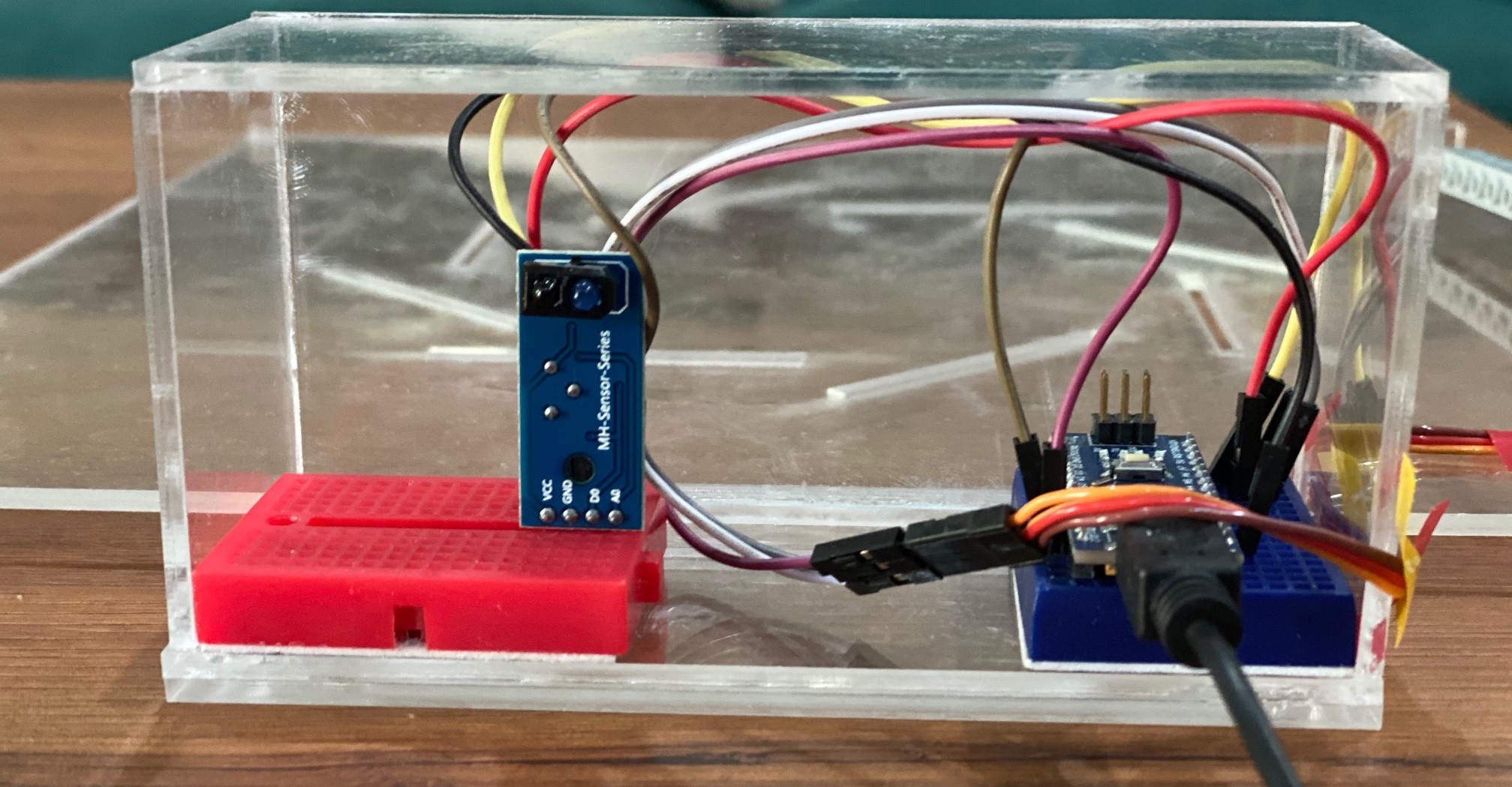
Finally, I measured the space needed for the electronics to design a box that will contain them. I used transparent acrylic
and glue to assemble the box.
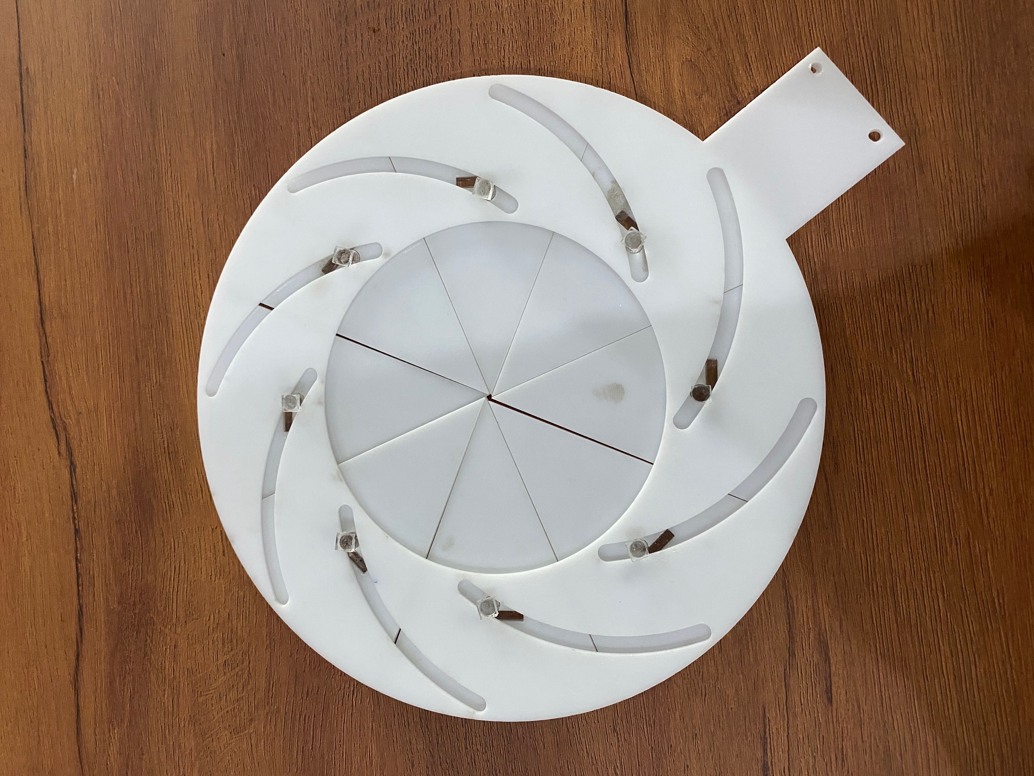
There are all the parts produced by the laser cutter.
Microcontroller Programming
Since all the parts are printed, I started the nex step. Which is
programming the microcontroller to do a movement action to move the handle.
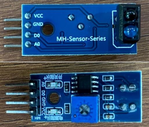
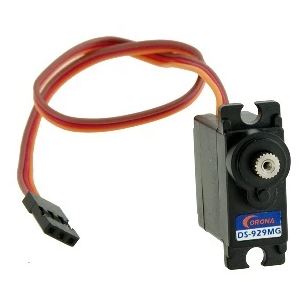
For the final project we should use both input and output device. So, I used a color sensor as an input device and a servo motor as an output device.
I explained how to connect these devices to the microcontroller using jumpers in Week #4
At the end of Week #4 I did an experiment to connect the sensor to the motor using this code.
And this was the result after pushing this code to the microcontroller.
I used this code, but it seems if the motor moves in that speed when it returns to its place and closing the iris,
the iris parts will move from their place.
In this case, I need to make it move slower while returning. So, I opened a built-in example in Arduino IDE called Sweep.
To test this code, I used it in TinkerCad as the following.
Press on start simulation to see its movement, you will notice that the motor here is moving really slow.
So, I merged this Sweep code with my code to conclude with a slower motion that will prevent the problem of having the parts moving from their place.
This was the resulted code, I uploaded this code to the microcontroller to see the result.
You can see in the video below how the movement of the motor changed and bacame slower.
Connection an Mechanisim
Connecting Motor's Movement to the Handle
After programming the microcontroller, I should think of a way to connect the motor's movement to
the handle.
I did so many trials to find the perfect solution, I ended with the solution of using a 2 part lego arm.
I connected the motor to one arm, and the handle to the other arm.
This is how I connected the lego arm to the motor.
And this is how the second lego arm is connected to the handle.
I had to do a hole in the handle to insert the screw.
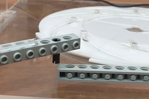
These two arms using a small black part that is design to connect lego parts that are in relative motion.
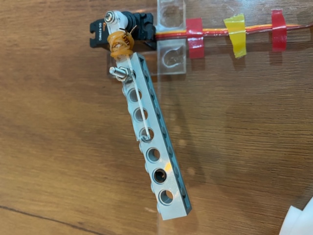
Here is a picture showing the connection between the motor and the handle.
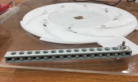
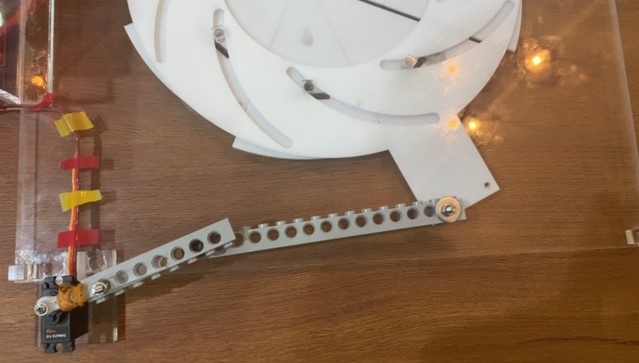
After connecting all the parts, it is time to test the mechanisim.
As You can see, the movement is perfect and the iris is opening and closing smoothly.
There is only one problem, which that the motor can not return back to its place thats why there is a noisy sound at the end.
And this will heat up the motor and damage it.
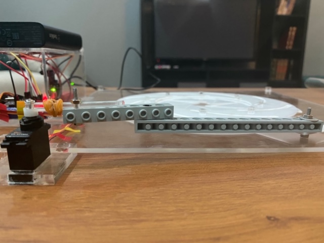
I figured out that this is caused because the level of the arms are not equal as you can see in this picture.
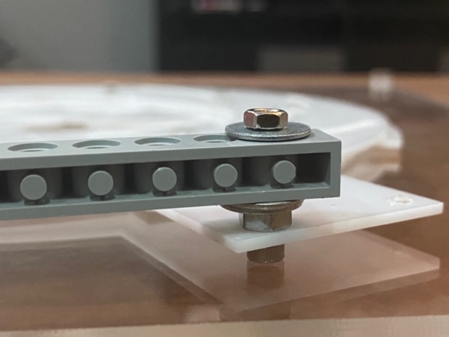
So, I but washers under this arm to make it at the same level of the lego arm that is connected to the motor.
This solved the problem and now the project is perfectly working.