Final Project
This week we worked on defining our final project “Smart Object” and started to getting used to the documentation process.
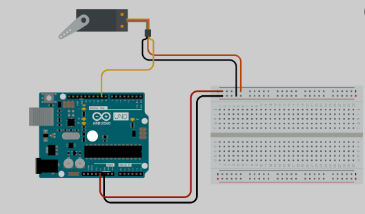
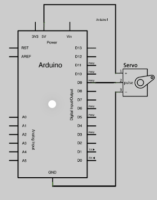
servo schematic arduino
You can connect small servo motors directly to an Arduino to control the shaft position very precisely.
Because servo motors use feedback to determine the position of the shaft, you can control that position very precisely. As a result, servo motors are used to control the position of objects, rotate objects, move legs, arms or hands of robots, move sensors etc. with high precision. Servo motors are small in size, and because they have built-in circuitry to control their movement, they can be connected directly to an Arduino.
Wiring Diagram
The best thing about a servo motor is that it can be connected directly to an Arduino. Connect to the motor to the Arduino as shown in the table below:
- Servo red wire – 5V pin Arduino
- Servo brown wire – Ground pin Arduino
- Servo yellow wire – PWM(9) pin Arduino
Sensor schematic arduino
Sensors are widely used in almost every field. Sensors give another dimension to your project and can be used in infinite applications. So, I decided to make this tutorial to help those new to sensors. I hope this will help you understand better.
there are different type of sensors which can record different type of data. All sensors work differently light sensors, ultrasonic sensor, gas sensor, humidity sensors.
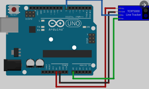
tracking sensor
The Track Sensor Module contains an IR Infrared reflection sensor that can be used for line following and edge detection. This sensor is uses one.
KY-033 tracking sensor
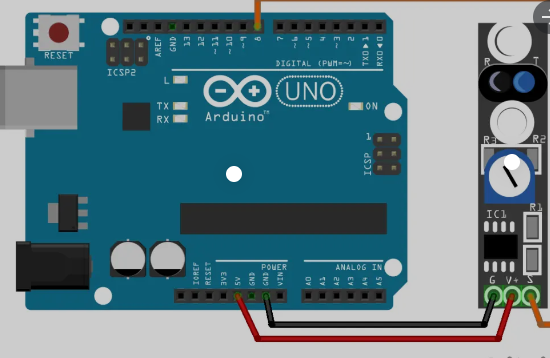
code for KY-033 sensor
int ldr=A0;//Set A0(Analog Input) for LDR.
int value=0;
void setup() {
Serial.begin(9600);
pinMode(3,OUTPUT);
}

void loop() {
value=analogRead(ldr);//Reads the Value of LDR(light).
Serial.println("LDR value is :");//Prints the value of LDR to Serial Monitor.
Serial.println(value);
if(value<300)
  {
    digitalWrite(3,HIGH);//Makes the LED glow in Dark.
  }
  else
  {
    digitalWrite(3,LOW);//Turns the LED OFF in Light.
  }
}


about final code
This code makes us control the rate at which the rose is about descending and ascending, and they also control the accuracy of the tilt or the height of the device itself, where it was placed at a rate of 180 degrees and the speed at a rate of 2.7 seconds, which helped the rose move beautifully and smoothly
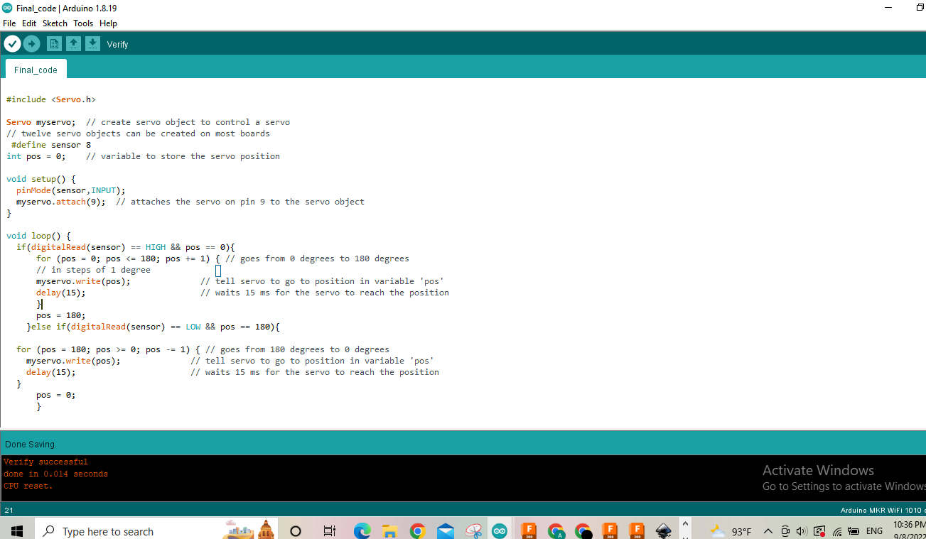
Final code
Servo myservo; // create servo object to control a servo
// twelve servo objects can be created on most boards
#define sensor 8
int pos = 0; // variable to store the servo position
void setup() {
pinMode(sensor,INPUT);
myservo.attach(9); // attaches the servo on pin 9 to the servo object
}
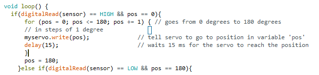
void loop() {
if(digitalRead(sensor) == HIGH && pos == 0){
for (pos = 0; pos <= 180; pos += 1) { // goes from 0 degrees to 180 degrees
// in steps of 1 degree
myservo.write(pos); // tell servo to go to position in variable 'pos'
delay(15); // waits 15 ms for the servo to reach the position
}
pos = 180;
}else if(digitalRead(sensor) == LOW && pos == 180){
for (pos = 180; pos >= 0; pos -= 1) { // goes from 180 degrees to 0 degrees
myservo.write(pos); // tell servo to go to position in variable 'pos'
delay(15); // waits 15 ms for the servo to reach the position
}
pos = 0;
}
}
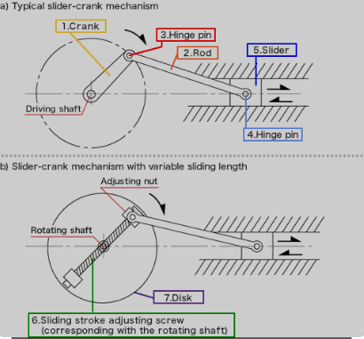
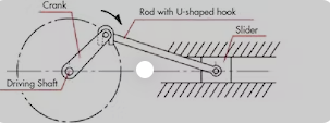
seem

I used this thing in order to control the height of the rose and its descent, knowing that I faced a problem here, but the solution came from the official Abdullah. We drilled a small hole in the device, and then we inserted the sim into the device, and then we made it in the form of a 90-degree angle, which helped me control the movement of the sim.
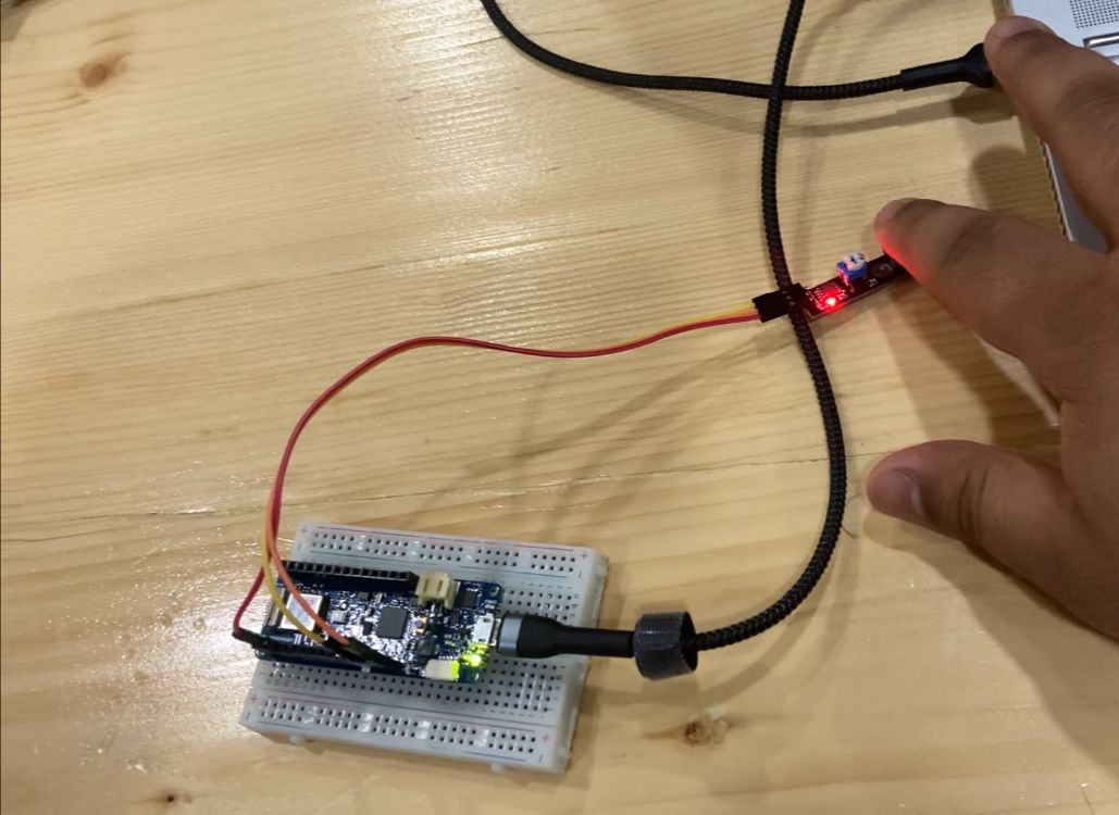
final result