4. Embedded programming
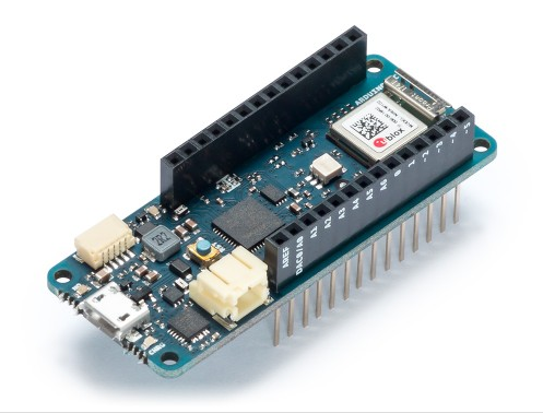
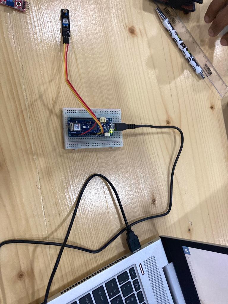
This week we worked on embeeded programing. We programmed a microcontroller. A microcontroller is a very small computer with diffrent functionality than a normal computer. what we were given is an Arduino, Arduino MKR 1010 wifi . which is a board with a microcontroller in it with some extra things.
The board contain the microcontroller, a wifi chip, reset button, micro usb port, usb to serial chip for PC interface, built in led and some other components.
microcontroller
How does it work ?
A microcontroller is embedded inside of a system to control a singular function in a device. It does this by interpreting data it receives from its I/O peripherals using its central processor. The temporary information that the microcontroller receives is stored in its data memory, where the processor accesses it and uses instructions stored in its program memory to decipher and apply the incoming data. It then uses its I/O peripherals to communicate and enact the appropriate action.
Microcontrollers are used in a wide array of systems and devices. Devices often utilize multiple microcontrollers that work together within the device to handle their respective tasks.
For example, a car might have many microcontrollers that control various individual systems within, such as the anti-lock braking system, traction control, fuel injection or suspension control. All the microcontrollers communicate with each other to inform the correct actions. Some might communicate with a more complex central computer within the car, and others might only communicate with other microcontrollers. They send and receive data using their I/O peripherals and process that data to perform their designated tasks.
Setup your microcontroller
Mine was arduino MKR1010 and here is the datasheet for it
which is available already on Arduino IDE so we just needed to download the library of it
After reading the datasheet i learned that:
The MKR WiFi 1010 is a miniature sized module containing a SAMD21G18A Processor, the Nina W102 Module, a crypto chip (the ATECC508), and a 2MByte SPI Flash.
steps
We will use this software to program and code our microcontroller. First you need to download the software from the following link

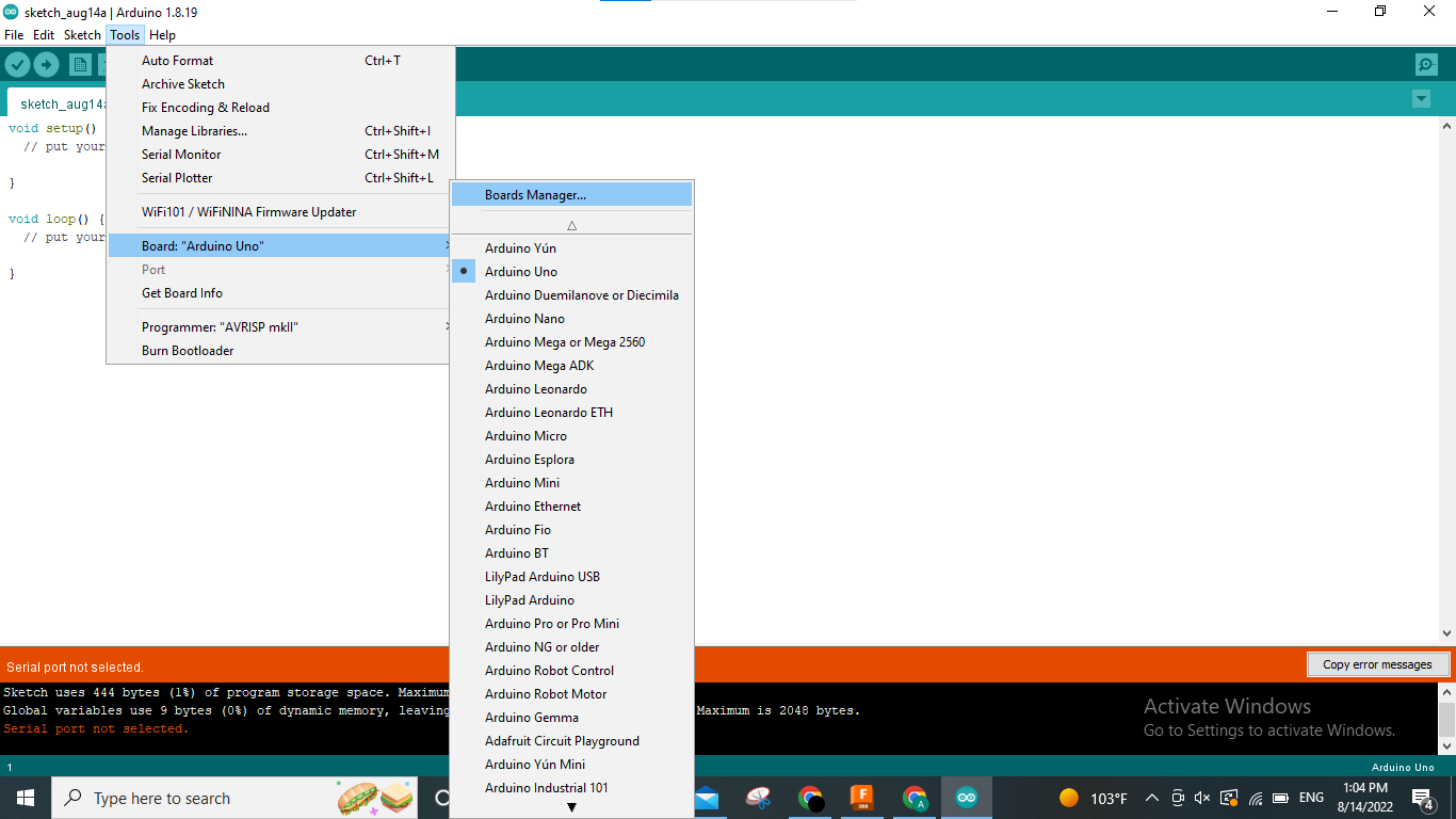
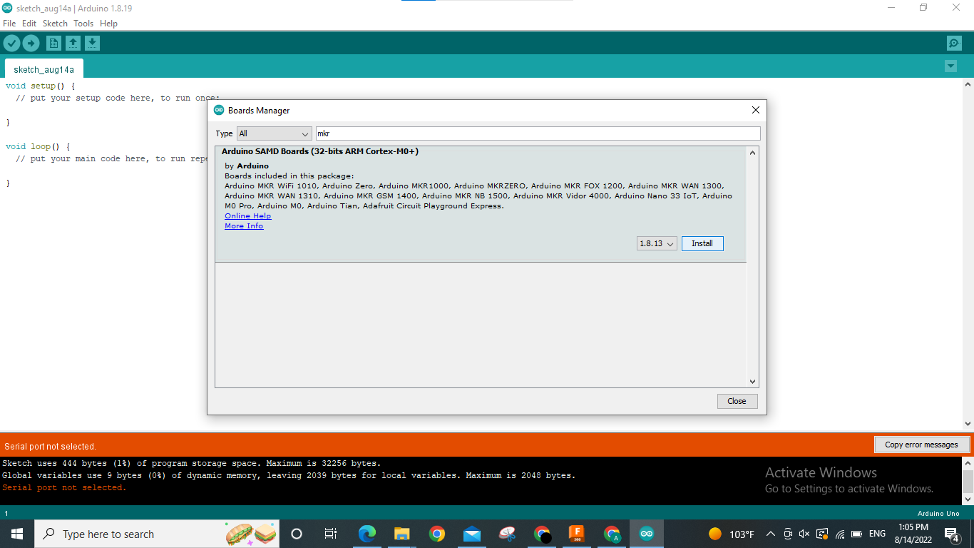
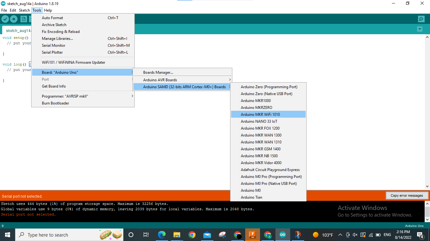
Tools/Board/Board manager find ..... and install it, i already install it
In this task, the objective is to make the microcontroller LED light blink.
From board manager, i searched for the model i worked on which is “mkr 1010 wifi ” and installed it so i could start working on it
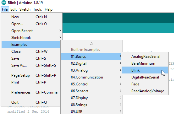
Blink
Simple programming code to make your microcontroller blink with the LED inserted on the board simple follow this:
Code Example of random blinking
/*
  Blink

  Turns an LED on for one second, then off for one second, repeatedly.

  Most Arduinos have an on-board LED you can control. On the UNO, MEGA and ZERO
  it is attached to digital pin 13, on MKR1000 on pin 6. LED_BUILTIN is set to
  the correct LED pin independent of which board is used.
  If you want to know what pin the on-board LED is connected to on your Arduino
  model, check the Technical Specs of your board at:
  https://www.arduino.cc/en/Main/Products

  modified 8 May 2014
  by Scott Fitzgerald
  modified 2 Sep 2016
  by Arturo Guadalupi
  modified 8 Sep 2016
  by Colby Newman

  This example code is in the public domain.

  https://www.arduino.cc/en/Tutorial/BuiltInExamples/Blink
*/

// the setup function runs once when you press reset or power the board
void setup() {
  // initialize digital pin LED_BUILTIN as an output.
  pinMode(LED_BUILTIN, OUTPUT);
}

// the loop function runs over and over again forever
void loop() {
  int A=random(500,5000);
  Serial.println(A);
  int B=random(500,5000);
  Serial.println(B);

  for(int j=0; j<10; j++){
    digitalWrite(LED_BUILTIN,HIGH);  // turn the LED on (HIGH is the voltage level)
    delay(A);                        // wait for a second
    digitalWrite(LED_BUILTIN,LOW);   // turn the LED off by making the voltage low
    delay(B);
  }                         // wait for a second

}
Code Example of writing hello in morse code
// the setup function runs once when you press reset or power the board
void setup() {
 // initialize digital pin LED_BUILTIN as an output.
 pinMode(LED_BUILTIN, OUTPUT);
}

// the loop function runs over and over again forever
void loop() {
 digitalWrite(LED_BUILTIN, HIGH);   // turn the LED on (HIGH is the voltage level)
 delay(1000);                       // wait for a second
 digitalWrite(LED_BUILTIN, LOW);    // turn the LED off by making the voltage LOW
 delay(500);                       // wait for a second
 digitalWrite(LED_BUILTIN, HIGH);   // turn the LED on (HIGH is the voltage level)
 delay(1000);
 digitalWrite(LED_BUILTIN, LOW);    // turn the LED off by making the voltage LOW
 delay(500);
 digitalWrite(LED_BUILTIN, HIGH);   // turn the LED on (HIGH is the voltage level)
 delay(1000);
 digitalWrite(LED_BUILTIN, LOW);   // turn the LED on (HIGH is the voltage level)
 delay(500);
 digitalWrite(LED_BUILTIN, HIGH);   // turn the LED on (HIGH is the voltage level)
 delay(1000);
 digitalWrite(LED_BUILTIN, LOW);   // turn the LED on (HIGH is the voltage level)
 delay(2000);

 digitalWrite(LED_BUILTIN, HIGH);   // turn the LED on (HIGH is the voltage level)
 delay(1000);
 digitalWrite(LED_BUILTIN, LOW);   // turn the LED on (HIGH is the voltage level)
 delay(2000);

 digitalWrite(LED_BUILTIN, HIGH);   // turn the LED on (HIGH is the voltage level)
 delay(1000);
 digitalWrite(LED_BUILTIN, LOW);   // turn the LED on (HIGH is the voltage level)
 delay(500);
 digitalWrite(LED_BUILTIN, HIGH);   // turn the LED on (HIGH is the voltage level)
 delay(2000);
 digitalWrite(LED_BUILTIN, LOW);   // turn the LED on (HIGH is the voltage level)
 delay(500);
 digitalWrite(LED_BUILTIN, HIGH);   // turn the LED on (HIGH is the voltage level)
 delay(1000);
 digitalWrite(LED_BUILTIN, LOW);   // turn the LED on (HIGH is the voltage level)
 delay(500);
 digitalWrite(LED_BUILTIN, HIGH);   // turn the LED on (HIGH is the voltage level)
 delay(1000);
 digitalWrite(LED_BUILTIN, LOW);   // turn the LED on (HIGH is the voltage level)
 delay(2000);

   digitalWrite(LED_BUILTIN, HIGH);   // turn the LED on (HIGH is the voltage level)
 delay(1000);
 digitalWrite(LED_BUILTIN, LOW);   // turn the LED on (HIGH is the voltage level)
 delay(500);
 digitalWrite(LED_BUILTIN, HIGH);   // turn the LED on (HIGH is the voltage level)
 delay(2000);
 digitalWrite(LED_BUILTIN, LOW);   // turn the LED on (HIGH is the voltage level)
 delay(500);
 digitalWrite(LED_BUILTIN, HIGH);   // turn the LED on (HIGH is the voltage level)
 delay(1000);
 digitalWrite(LED_BUILTIN, LOW);   // turn the LED on (HIGH is the voltage level)
 delay(500);
 digitalWrite(LED_BUILTIN, HIGH);   // turn the LED on (HIGH is the voltage level)
 delay(1000);
 digitalWrite(LED_BUILTIN, LOW);   // turn the LED on (HIGH is the voltage level)
 delay(2000);


  digitalWrite(LED_BUILTIN, HIGH);   // turn the LED on (HIGH is the voltage level)
 delay(2000);
  digitalWrite(LED_BUILTIN, LOW);   // turn the LED on (HIGH is the voltage level)
 delay(500);
  digitalWrite(LED_BUILTIN, HIGH);   // turn the LED on (HIGH is the voltage level)
 delay(2000);
  digitalWrite(LED_BUILTIN, LOW);   // turn the LED on (HIGH is the voltage level)
 delay(500);
  digitalWrite(LED_BUILTIN, HIGH);   // turn the LED on (HIGH is the voltage level)
 delay(2000);
  digitalWrite(LED_BUILTIN, LOW);   // turn the LED on (HIGH is the voltage level)
 delay(500);
}
Code Example of transfering delay
  Blink

  Turns an LED on for one second, then off for one second, repeatedly.

  Most Arduinos have an on-board LED you can control. On the UNO, MEGA and ZERO
  it is attached to digital pin 13, on MKR1000 on pin 6. LED_BUILTIN is set to
  the correct LED pin independent of which board is used.
  If you want to know what pin the on-board LED is connected to on your Arduino
  model, check the Technical Specs of your board at:
  https://www.arduino.cc/en/Main/Products

  modified 8 May 2014
  by Scott Fitzgerald
  modified 2 Sep 2016
  by Arturo Guadalupi
  modified 8 Sep 2016
  by Colby Newman

  This example code is in the public domain.

  https://www.arduino.cc/en/Tutorial/BuiltInExamples/Blink
*/
int onBlinks=0;
int offBlinks=0;

// the setup function runs once when you press reset or power the board
void setup() {
  // initialize digital pin LED_BUILTIN as an output.
  pinMode(LED_BUILTIN, OUTPUT);
  digitalWrite(LED_BUILTIN,LOW);  // set the pin value on low at the begin
  Serial.begin(9600);
}

// the loop function runs over and over again forever
void loop() {
  while (onBlinks==0){
    Serial.println("How long do you want the LEDs to stay on in ms?");  // prompt user for input
    while (Serial.available() ==0){
      // wait for user to input data
    }
    onBlinks = Serial.parseInt();  // read the data the user has input
  }

  while (offBlinks==0){
    Serial.println("How long do you want the LEDs to stay off in ms?");  // prompt user for input
    while (Serial.available() ==1){
      // wait foe user to input data
    }
    offBlinks = Serial.parseInt();  // read the data the user has input
  }

  for(int i=0; i<5; i++){
    digitalWrite(LED_BUILTIN,HIGH);  // turn the LED on
    delay(onBlinks);  // wait for a second
    digitalWrite(LED_BUILTIN,LOW);   // turn the LED off
    delay(offBlinks);
    }
  }
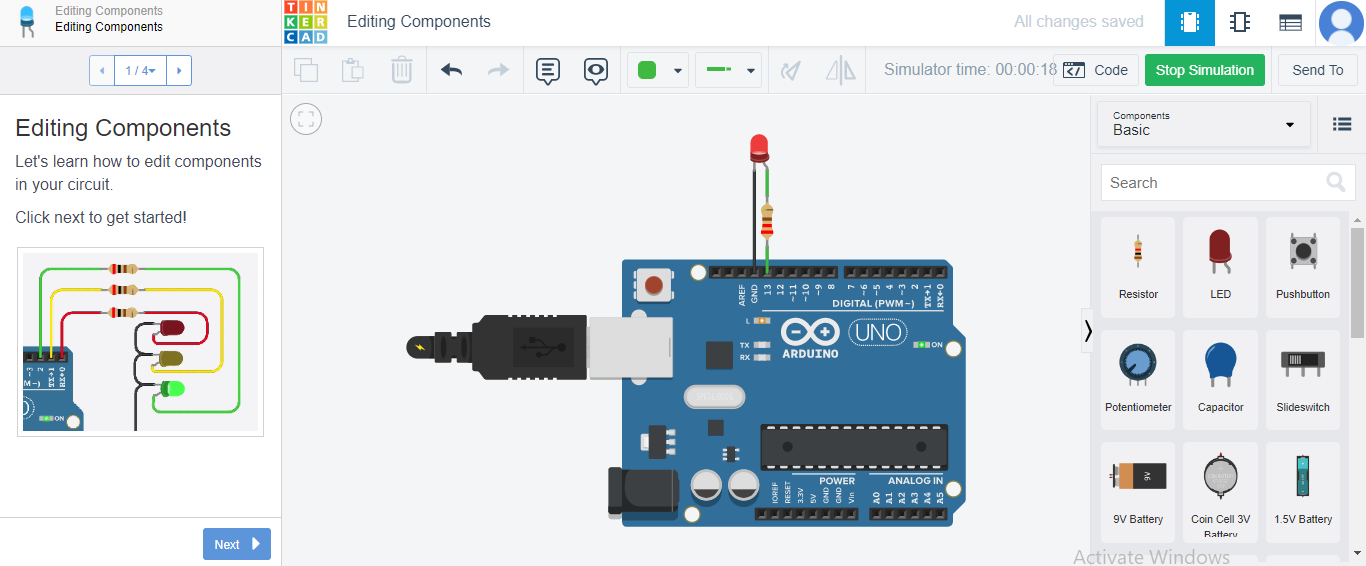
tinker cad
Making a light fade off and turning back on.
This is how the circuit would look like.
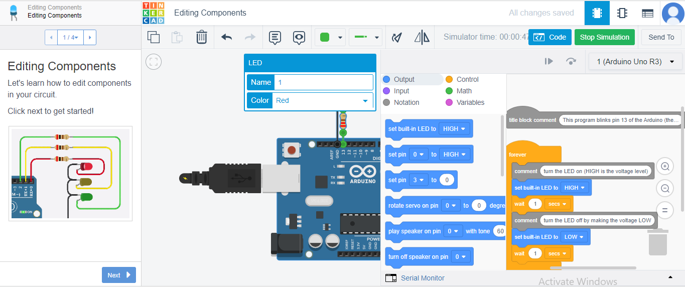
The code would look like this.
copy the code and chak it in the arduino
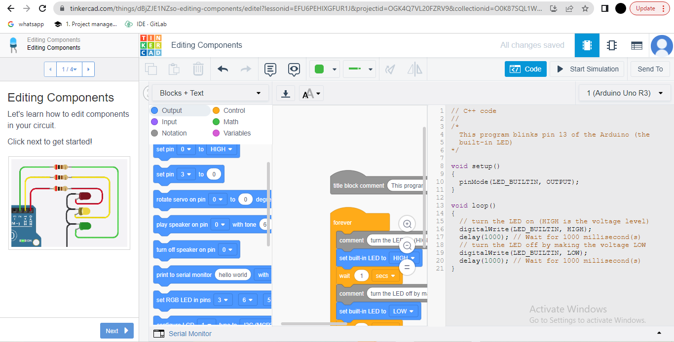
// C++ code
//
/*
  This program blinks pin 13 of the Arduino (the
  built-in LED)
*/

void setup()
{
  pinMode(LED_BUILTIN, OUTPUT);
}

void loop()
{
  // turn the LED on (HIGH is the voltage level)
  digitalWrite(LED_BUILTIN, HIGH);
  delay(1000); // Wait for 1000 millisecond(s)
  // turn the LED off by making the voltage LOW
  digitalWrite(LED_BUILTIN, LOW);
  delay(1000); // Wait for 1000 millisecond(s)
}