3. Computer Controlled Cutting
Vinyl cutter
what is Cricut Explore Air 2?
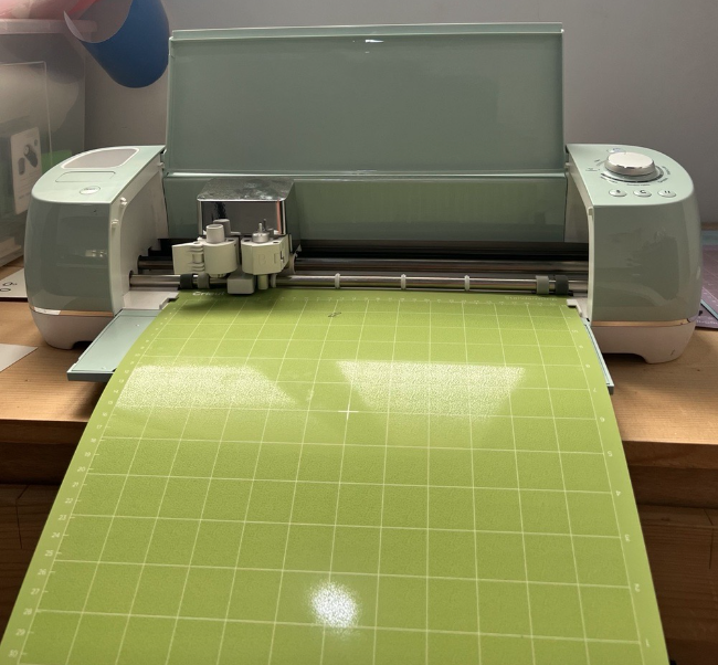
- Cricut explore air 2 cutter (vinyl cutter) was manually utilized to make 2D designs into stickers that can be used for various purposes. It uses blades with a command coming from a specific software (Cricut design space software) to cut the imported design on the sticking sheet. The vinyl cutter looks as shown below
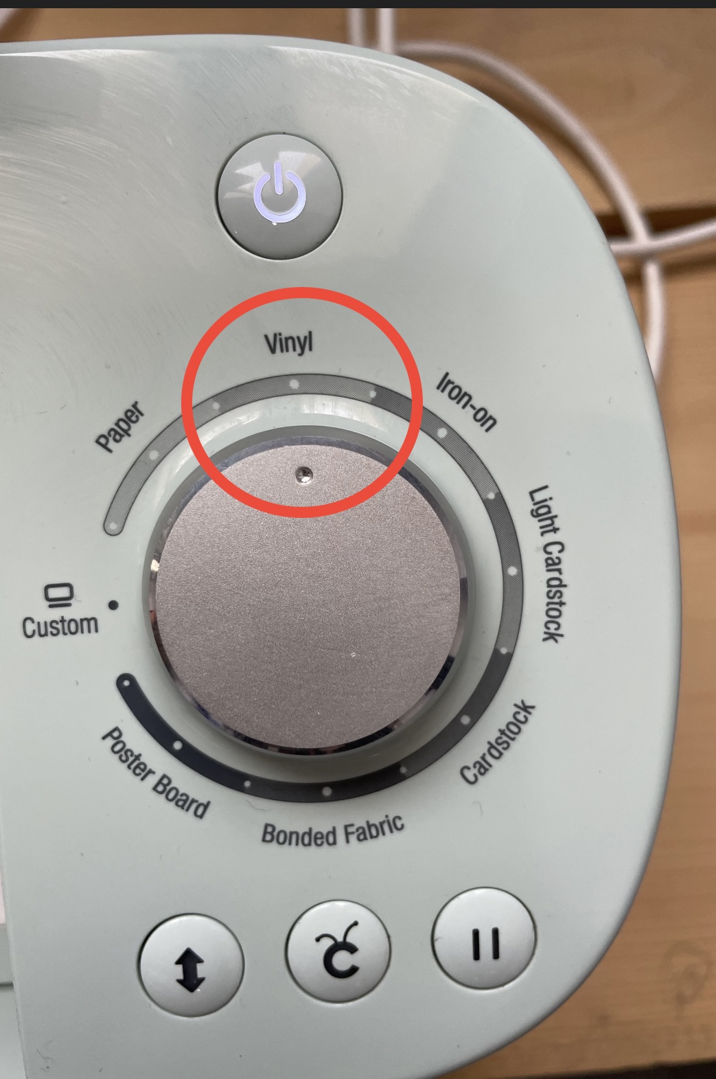
we started to learn how to operate the ‘Cricut Explore Air 2’ DIY cutting machine with the help of the supervisors. First, we downloaded the software that is specifically used for the machine. After that, we searched for the shape and type of the material of the stickers we wanted to cut and adjusted the machine settings accordingly. for vinyl we selected the vinyl option for the power
1. Choosing the design
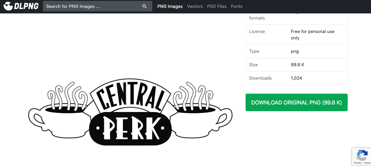
Using google search engine, I searched for the design I wanted, to make easy cutting it is preferred to add silhouette to your searching and pick the design in black and white with clear and not very thin lines. As shown, I choose the design “central perk “from the DLPNG website (link below ).
2. Using Cricut Explore Air 2:
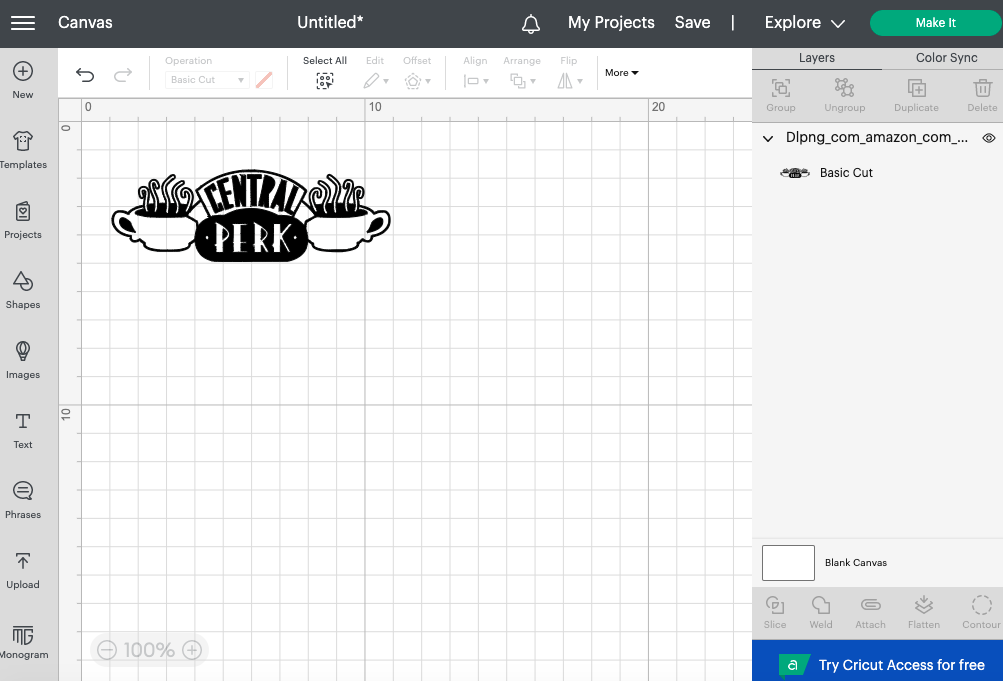
- A simple design was upload and it would be adjusted based on the location of the sticky sheet used:
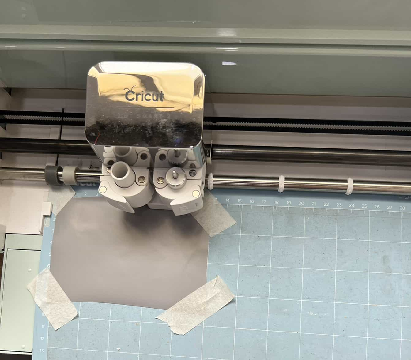
- A sticky sheet is adjusted based on the dimensions of the design with an extra offset to make sure that the cutting procedure succeeds, and it does not go off the edges. Later on this sticker is put into the sheet used in the vinyl cutter After that, the sheet is put inside the vinyl cutter to fit it inside the machine to prepare it for cutting
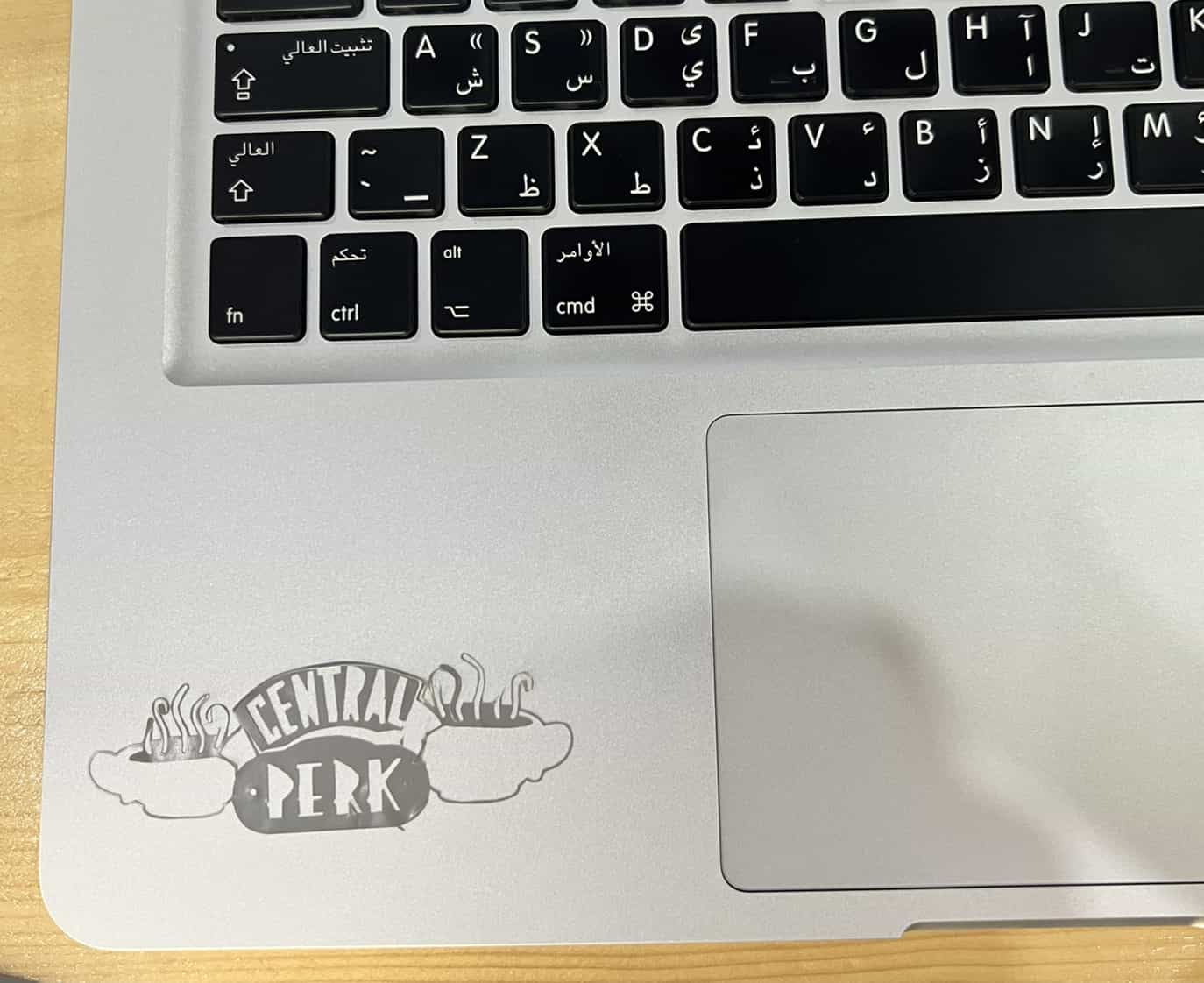
- This is how the sticker will look after removing the sticky material surrounding the design and after removing the excess material, the design will look like this
Laser Cutter
Group Assignment
In this group assignment we explored the characteristics of the co2 laser cutter including the focus, power, speed, rate, kerf, and joint clearance. More details are mentioned below
Documentation is done with the help of my colleague Tasneem.Mearaj
- The lasecutter Uses focused high-power beam that is powerful enough to cut different materials through burning it. This beam is directed through optics and computer numeric control to cut the required shapes. To start and stop the laser the start(Green) and stop(Red) buttons are used.
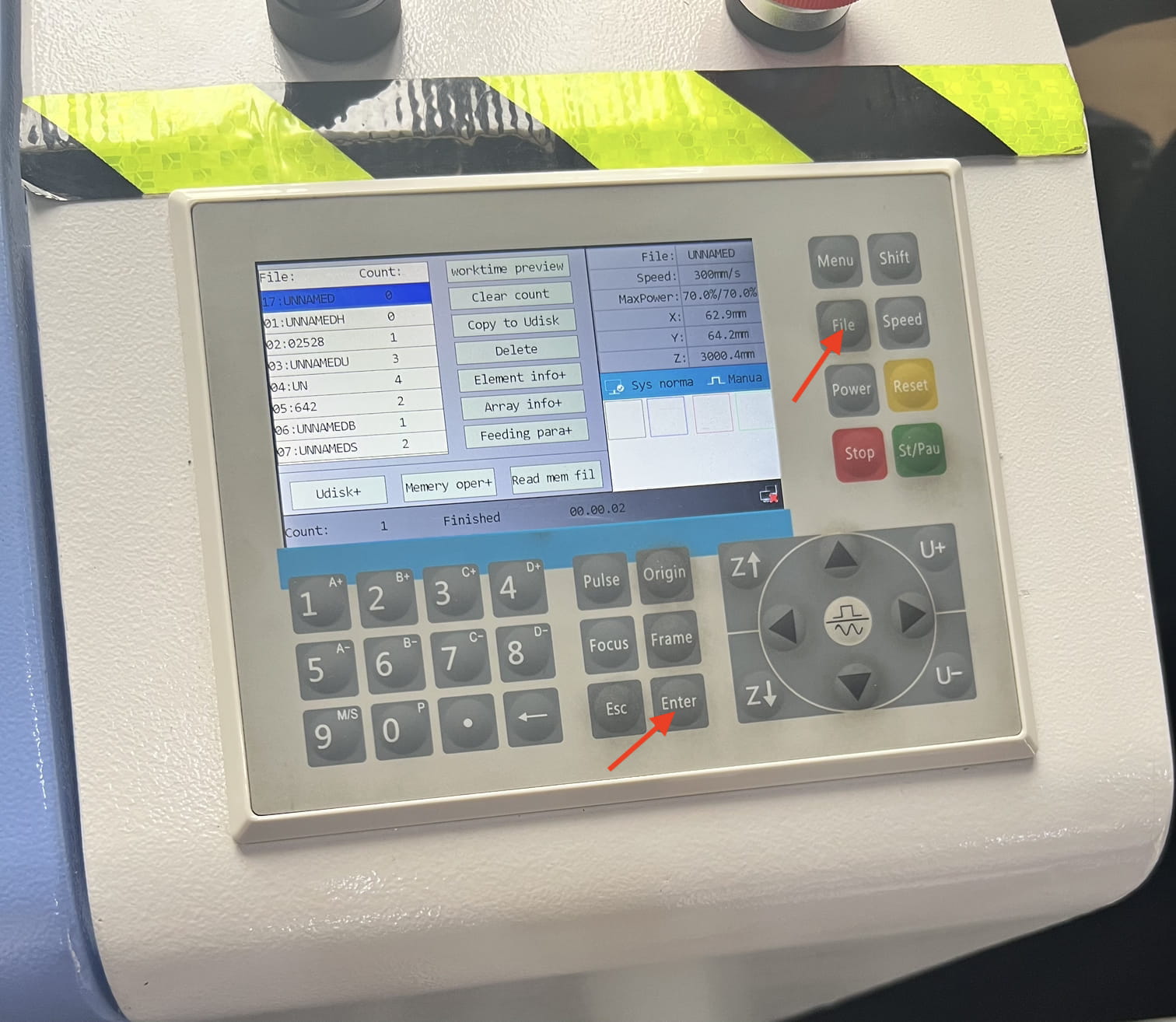
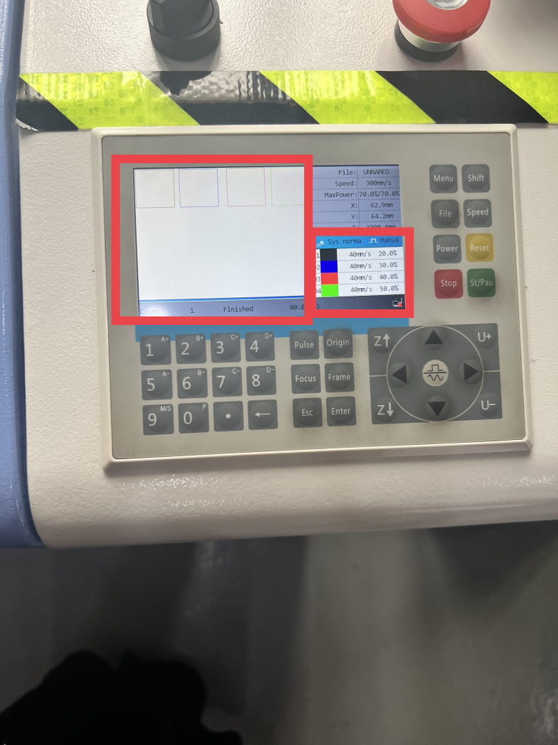
- We sent the design file from the program tp the lasercutter by clicking on download, After that we went to the machine and when the file is transfered we can clicked on the File button and then on the Enter button after selecting the file.
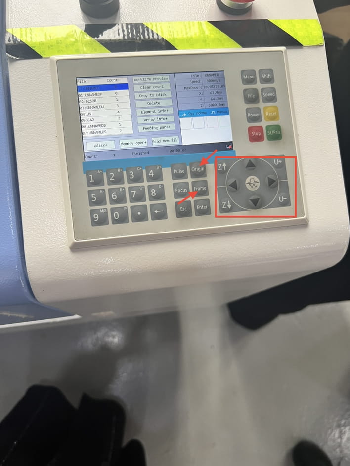
- To adjust the laser, we can move it in x-axis and y-axis using the arrows and z-axis by using the Z buttons. we set the origin of the design by clicking the origin button, the frame button is very useful where the laser moves to show the frame of the design and make sure it’s within the boarders before cutting it.
Focus
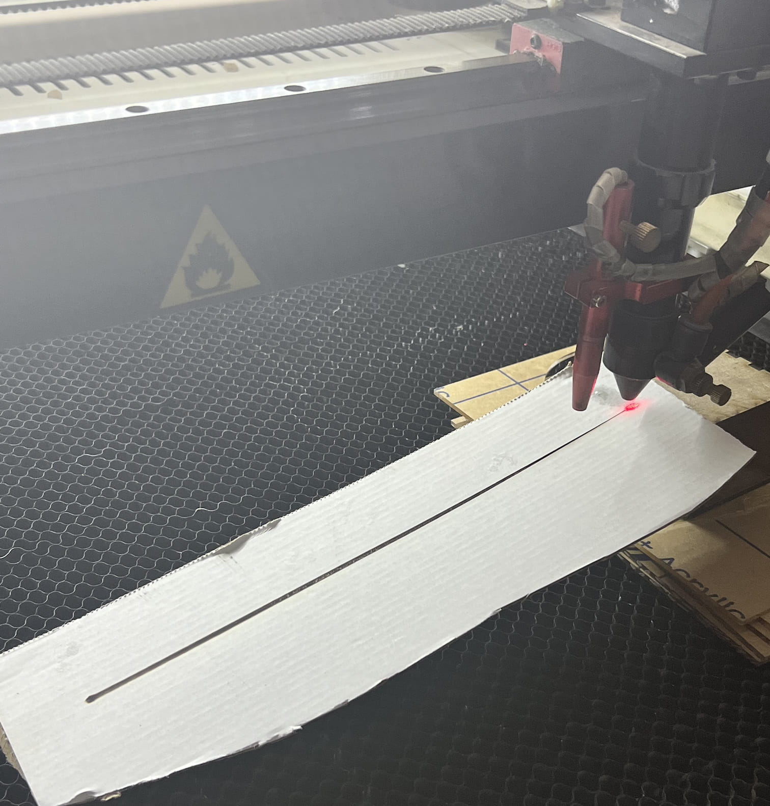
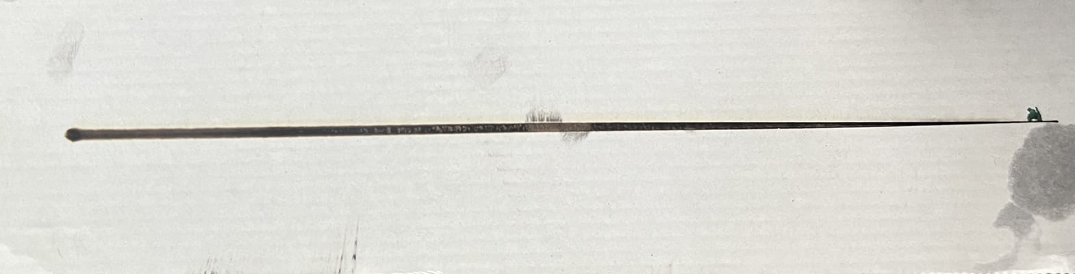
- To get a clean and neat lines for the design the focus must be adjusted it, to check the focus of the laser, a sample of the material is used and placed with change in elevation. As shown in the pictures below, at the very begining the line is not neat then it gets clean and more neat at about 8mm (space between the material and the laser). the further the space the less accurate the cutting.
Power And Speed
-
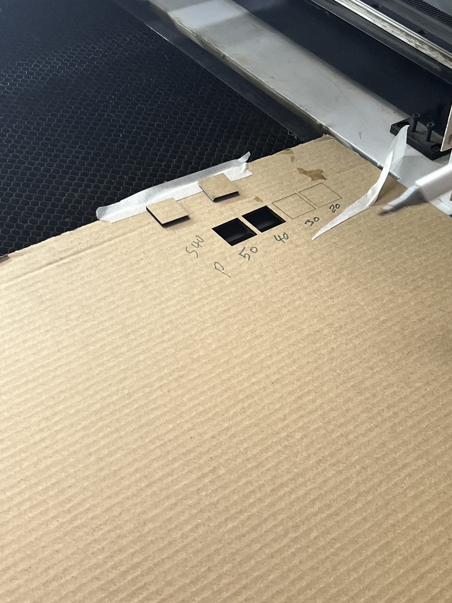
To find the power needed to cut the design perfectly. Four arrangements of the power and speed were tested to determine the best one for cutting the material.
-
For testing, we drew 4 squares with different colours, we varied the power and kept the speed constant for all (40 mm\s ). then we sent it to the machine. As shown, the best settings came out to be (speed=40 and power= 50) where the material is finely cut.
-
In general, high power and low speed settings are used for cutting thick and strong materials, while low power is used to engrave the surfaces.


Rate
The laser rate or number of laser pulses per second can be changed affecting the power received by the material becoming another factor that has to be considered aside the power and speed settings for effective cutting.
Kerf and Joint Clearance
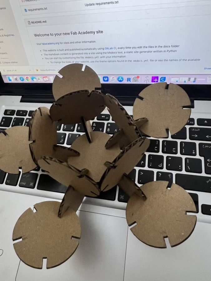
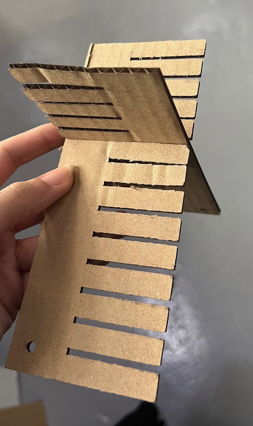
Complex models can be created by joining the 2D designs cut by the laser cutter through making joints. As some of the material gets wasted when burning it by the laser, it has to be taken into consideration when making the kerf measurements.
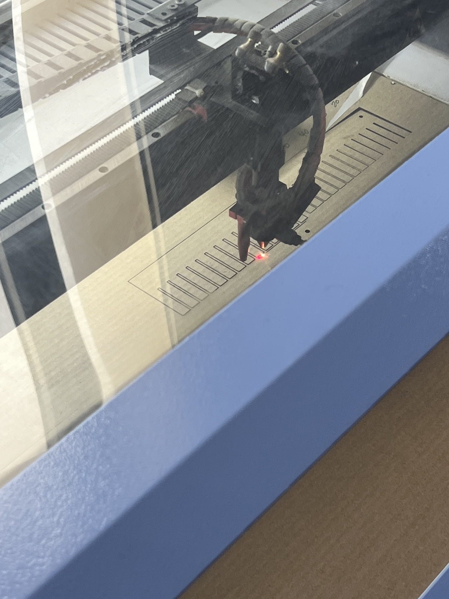
Comb models with various teeth widths were used to check for the suitable kerf width for the used material for the joint to perfectly fit each other.

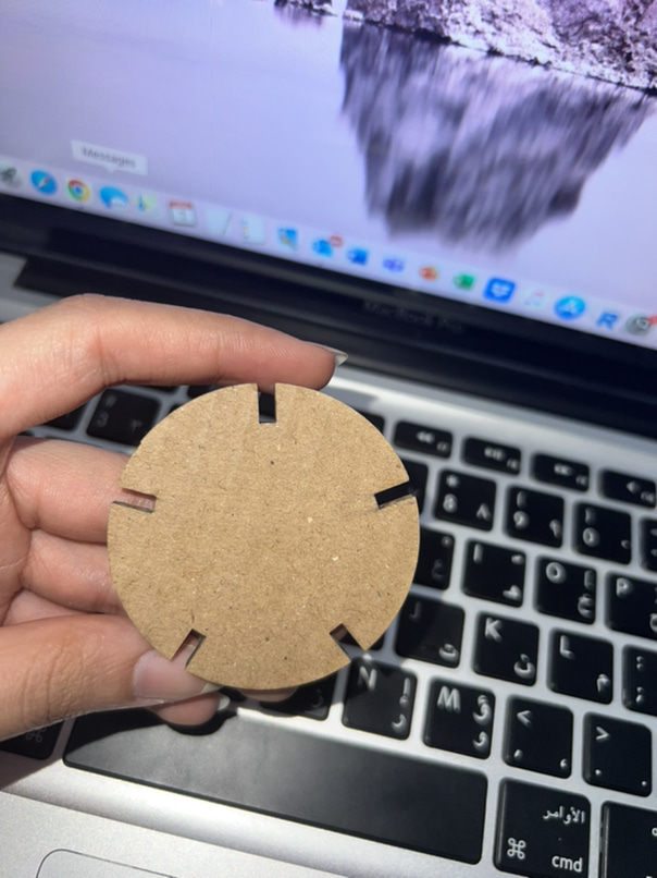
Individual Assignment
-
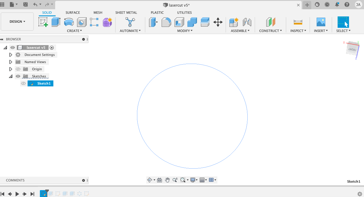
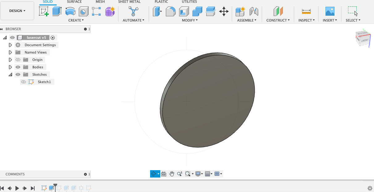
using Fusion360, i started drawing my sketch
-
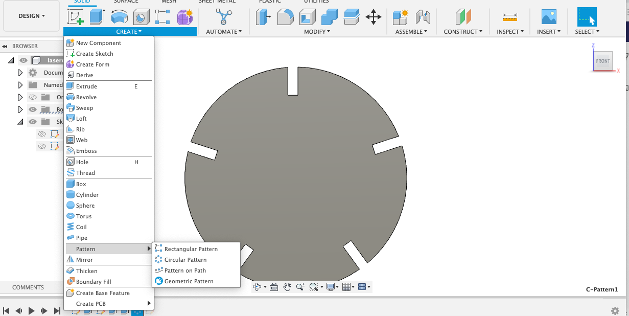
Then i added a joint to the sketch
-
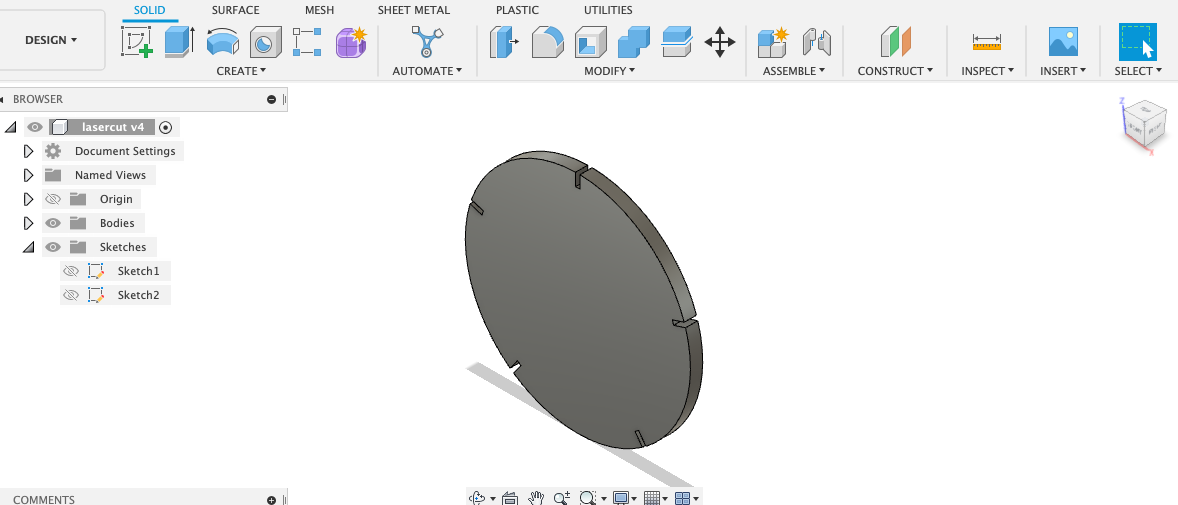
I used the circular pattern feautre to duplicate the joint.
-
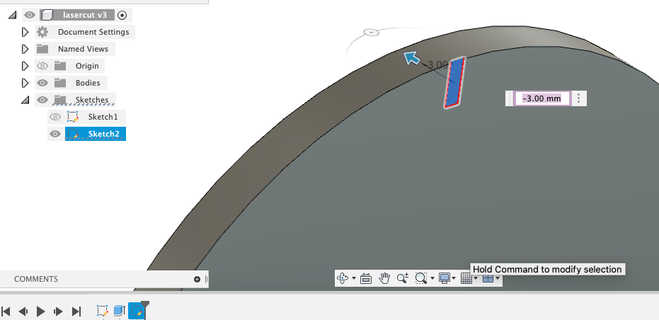
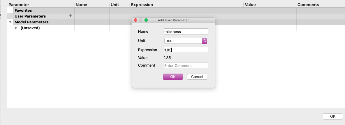
I added a parameter and named it thicness. therefore, whenever i want to make last minute changes to the thickness of the joints, i can do it easily
-
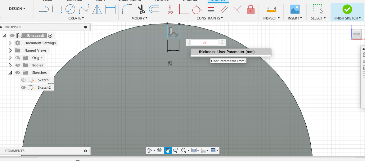
I went to the joint sketch and made the change using the parameter feature, by writing the name of the parameter i choosed
-
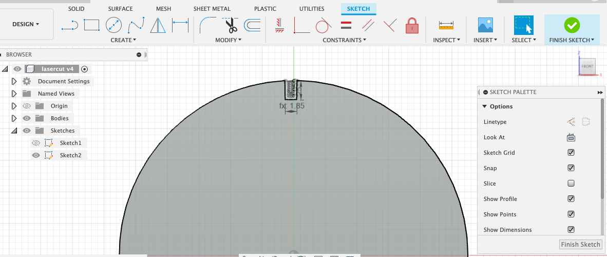
As a result the thickness of the joint changed. so as the other joints.
-
I did cut the pieces using the laser cutter with the settings we choosed in the group assignment
- This is the final result