2. Computer Aided design 
The objectives for the second week were to be introduced to various computer-aided design softwares and programs that can be utilized to design a variety of mechanisms in either 2D or 3D form. This week, we used few softwares/programs to acquaint ourselves and broaden our options based on whether the software was simpler to work on or had more design advantages than the other. Furthermore, the aim for this week is to create a minimum of two designs using different 2D and 3D softwares, while discussing the process and inspiration behind the designs.
1. Introduction 
Computer-Aided Design also known as CAD is the process of creating a 2D drawing and 3D models into a real life object digitally before proceeding to the manufacturing and fabrication process. with the help of CAD you can turn your ideas into objects that can be used in the real world by modifying, evaluating and simulating the design and its functionality to ensure the design is safe and functional before being produced, its an easy way to test any product before moving on to the manufacturing process. here are some great CAD software that are commonly utilized in the industry;
- SolidWorks
- Fusion 360
- AutoCAD
- Ansys Mechanical
- KeyCreator
Since I’m already familiar with SolidWorks and Ansys softwares and both are great in their own ways, i decided to try a new software for this week which is Fusion 360 and give my opinion on how easy and beginner friendly the software is.
Before proceeding with the 2D and 3D softwares, it is essential to understand and differentiate between a raster and a vector .
Raster which is also known as Bitmaps, are made up of different and individual pixelated color that make up the whole image. in simpler words it a punch of tiny squares with different colors that make up a whole detailed image that doesn’t look pixelated unless zoomed in. the lower the number of pixels an image has the more the image looks like a low-grade.
Vector In contrast to raster graphics, which are made up of colored pixels organized to produce a picture, vector graphics are composed of paths, each of which has a mathematical formula that specifies the path’s geometry as well as the color it should be filled with or surrounded by. Vector pictures maintain their look no matter how big they are because mathematical rules determine how the image is produced. They are endlessly flexible and scalable.

Info
To have a better understanding of raster and vectors visit PsPrint website.
2. 2D Softwares 
2.1 Cuttle xyz Website
Cuttle XYZ is mainly used as a design tool for digital cutting machines (Laser cutting machine, vinyl machine) as it is an easy to use and guide through vector editor. Cuttle has great features that can be utilized to design a variety of complex 2D designs within a few clicks. Something that caught my attention and made Cuttle stand out to me is the Generators where you can create an object such as a box or a keychain by just plugging in the parameters while it generates it for you automatically.
Tip
if you want to know more about Generators visit Introducing Cuttle
The steps to use Cuttle xyz :
1. Visit Cuttle xyz website or search for it using the browser2. Click on the first link
3. Sign Up with google or your personal email
4. Click on new project, to start with the design
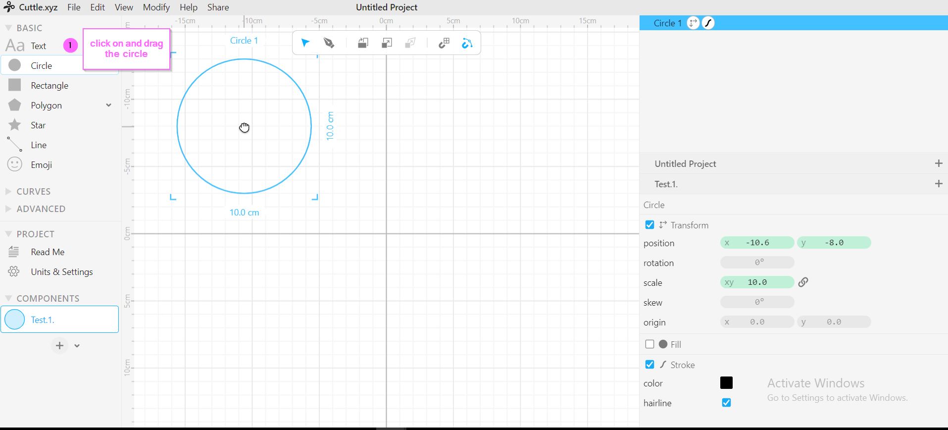
5. Click on and Drag the circle to the middle
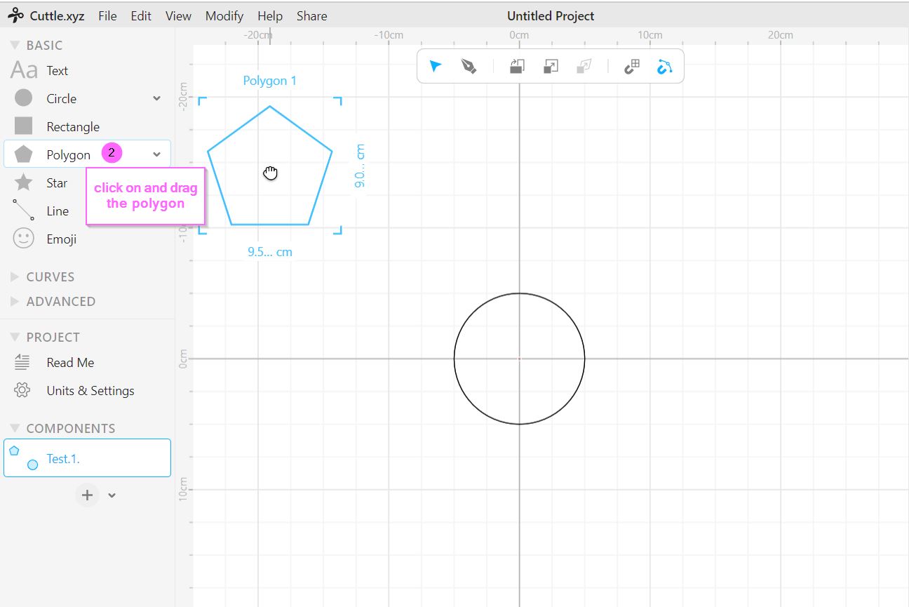
6. click on and drag polygon, twice one at the bottom and one at the top of the circle
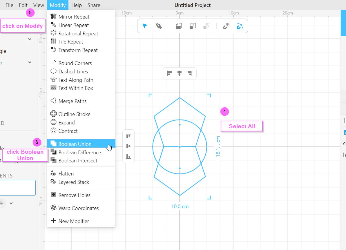
7. Select All > click on modify > Boolean Union (to merge all the shapes into one)
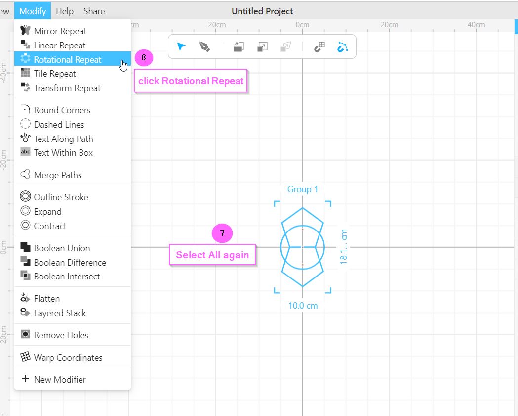
8. Select All > click on modify > rotational repeat > drag the red dot to the bottom

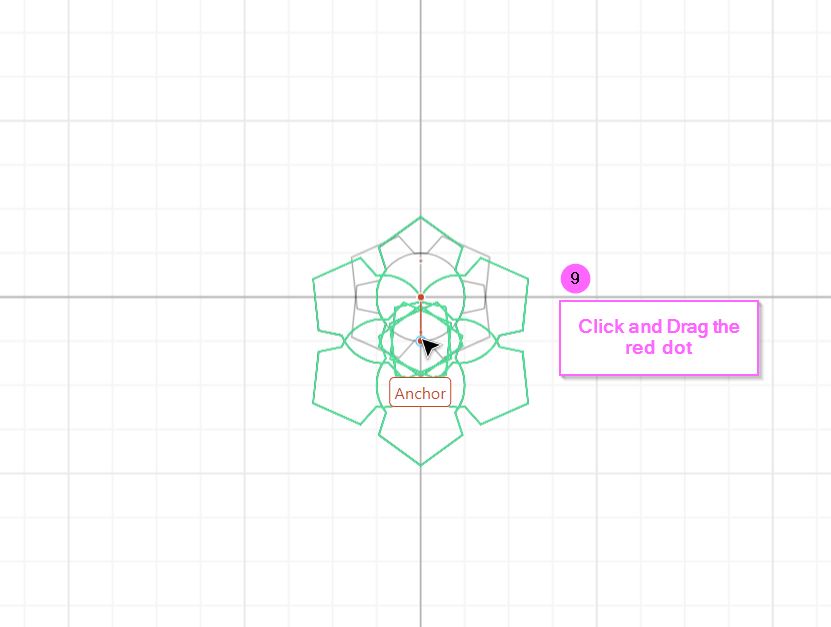
The final 2D Design that is created to resemble a flower

2.2 Inkscape Software
Inkscape is a software used for vector graphics designs and editing imported graphics as well. inkscape is quite different than cuttle xyz yet has similar tools, however, inkscape has far more variety of tools and features. inkscape can turn imported images into SVG files by tracing image uploaded.
The steps to use inkscape :
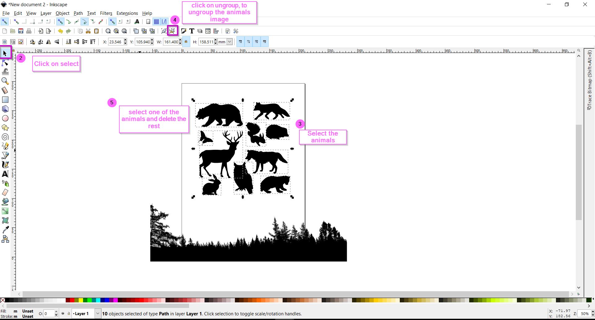
1. Open Inkscape software2. Upload the images in an SVG format
3. Select the image of the animals > ungroup the image to be able to select one animal > delete the rest
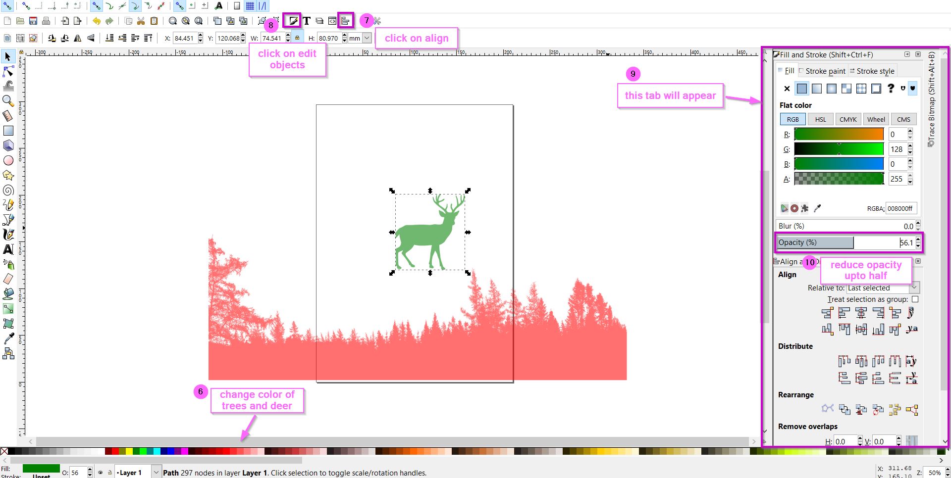
4. Add Color to both images > Click on align > click on edit object > decrease the opacity of both images
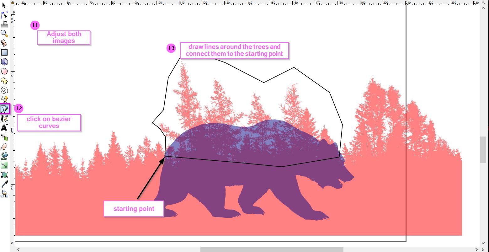
5. Click on "Bezier curves and straight lines" to select the trees around the bear
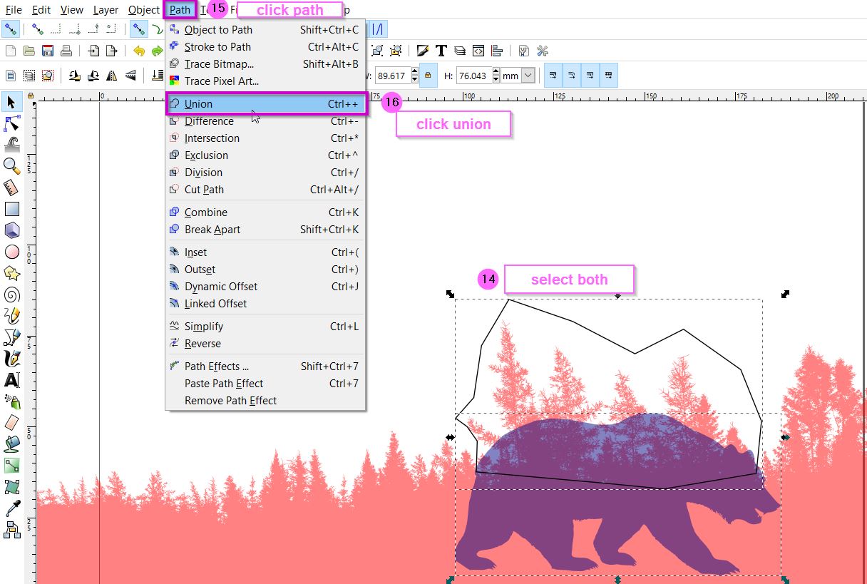
6. Select the bear image and the trace made around the Trees > click on path > Union
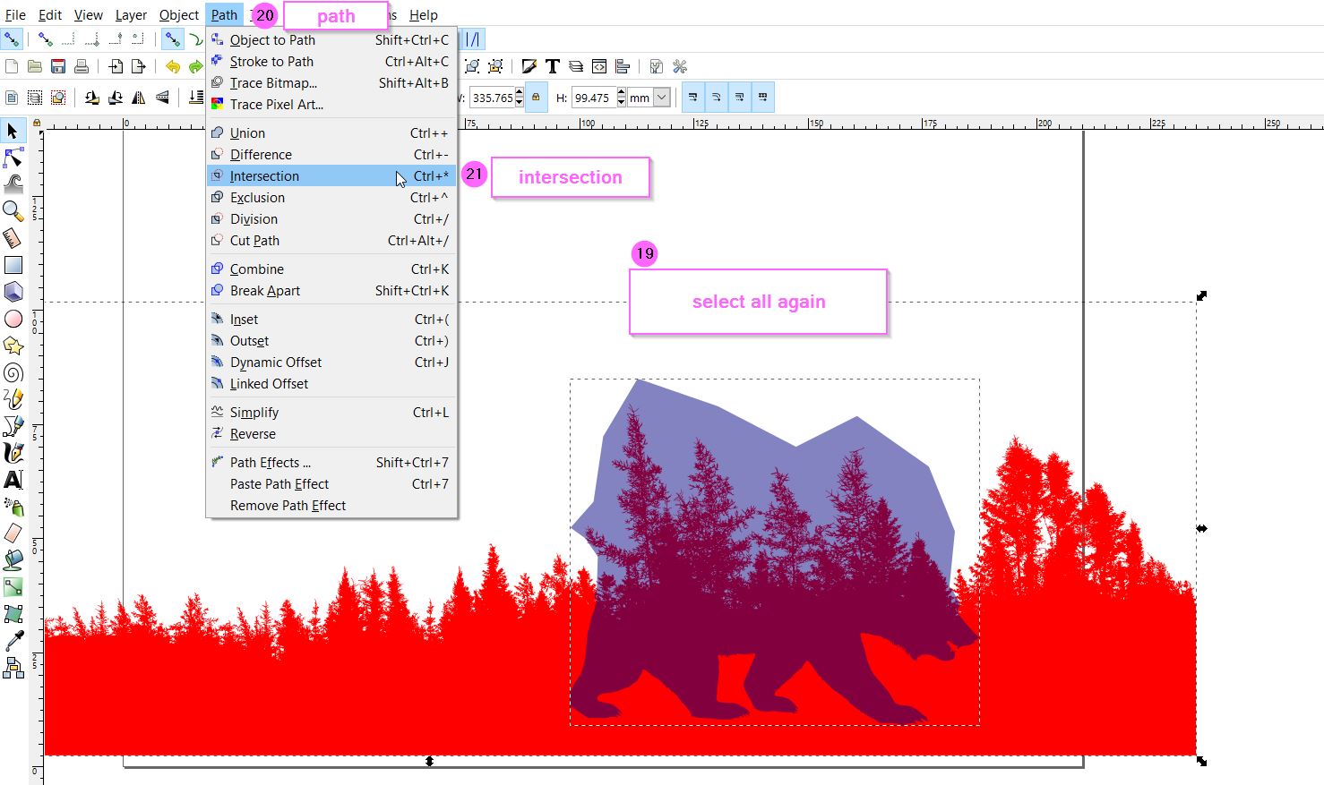
7. Select all images > ungroup
8. Select All images again > path > intersection
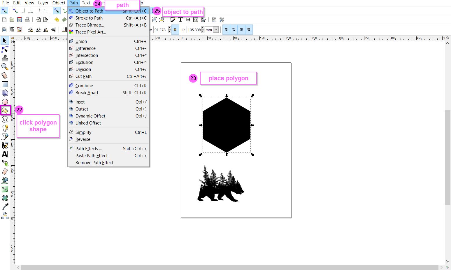
9. click polygon shape > create a polygon shape in the middle
10. Click on the polygon > path > object to path
11. Click on node > click selected nodes > select the middle part > move arrows upwards while clicking (Ctrl + shift)
12. copy the bear > layers > add a layer > paste the bear on the second layer
13. move the bear on top of the polygon and adjust it accordingly
Tip
To select multiple images click on “shift” while selecting multiple images at once.


The final 2D design

3. 3D softwares 
3.1 Tinkercad website
Tinkercad is a free online program that is used to create 3D modules for 3D printing. It is an easy and basic program that can be used by any entry level student that is interested in constructing solid geometry. The program was indeed relatively simple to use; however, it had limitations such as the inability to build complex and intricate 3D modules because it is often used for simpler designs due to its limited functions and tools. Nonetheless, I suggest it for beginners with no CAD or constructive solid geometry knowledge as it will be helpful moving to more complex programs.
The steps to sign up in Tinkercad :
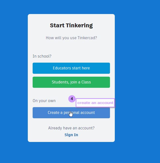
1. Visit Tinkercad website or search for it using the browser2. Click on the first link
3. Sign Up with google or your personal email
4. Click on New at the right top > click on 3D design to start Designing


The steps to 3D Design on Tinkercad:
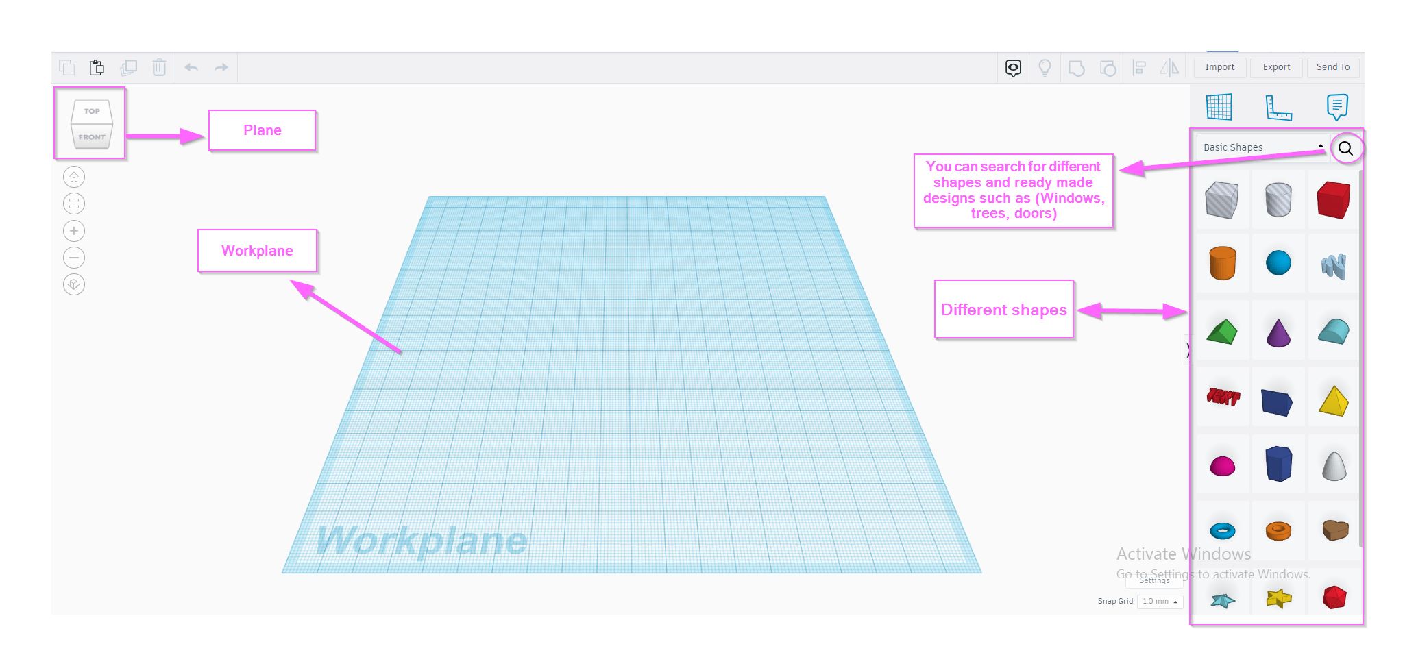
1. Click on New at the top right > Click 3D Design to start designing on the front plane2. you will be directed to the workplane page to design a 3D object
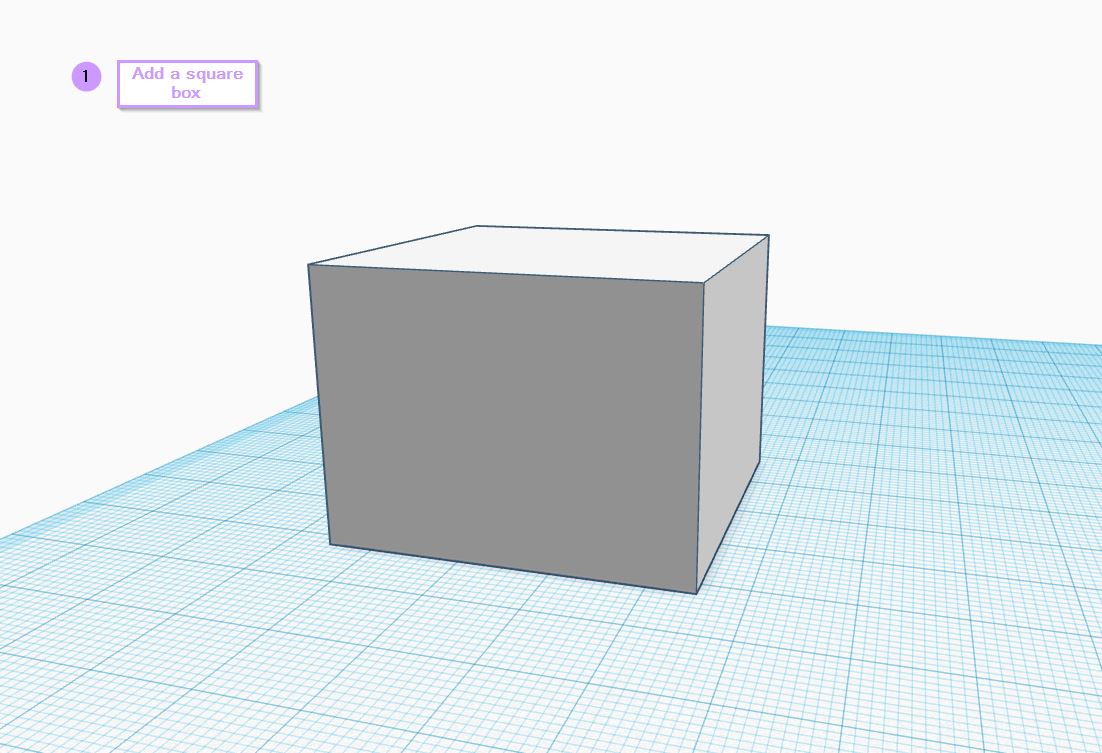
3. Click on the square shape and place it in the middle after adjusting the dimensions
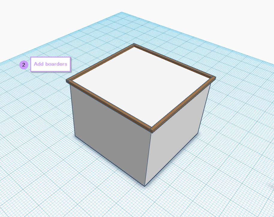
4. Add Borders by using a rectangle shape and adjusting the dimension to be extremely thin to resemble a border > place it around the edges of square's top
5. Add a Rectangle shape on top of the square
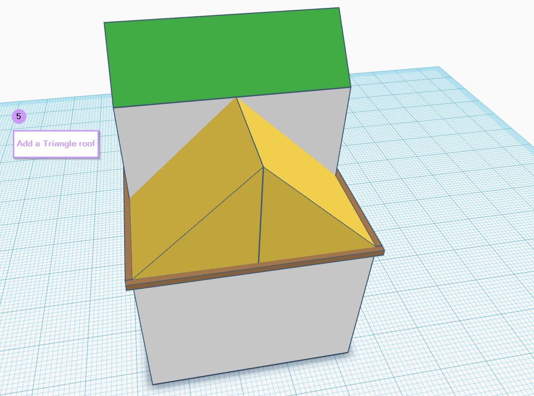
6. Add two triangles side by side to the top of the square
7. Add an elongated triangle on the top of the rectangle
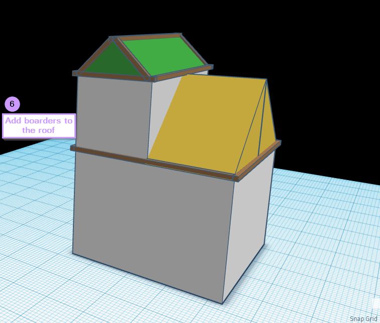
8. Add boarders to the elongated triangle and the sides of the square to give it depth
9. Using the search shapes, search for windows and a door > adjust their sizes > place them around the house block
10. Using the text shape > write a number for the house > adjust the size and place it near the door
11. Using the rectangle shape i made a fence
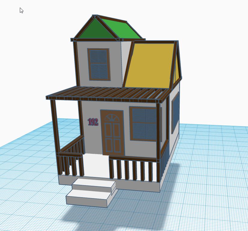
The inspiration of the 3D taken from my Roblox Account

Designing the 3D module steps


The Final Result of the 3D design using Tinkercad, the inspiration behind this 3D model is that i wanted to create a house that resembles the house/building that i have created on my Roblox game. its definitely not the same as the one in Roblox but definitely has similarities especially the color Platte and structure.
3.2 Fusion 360 software
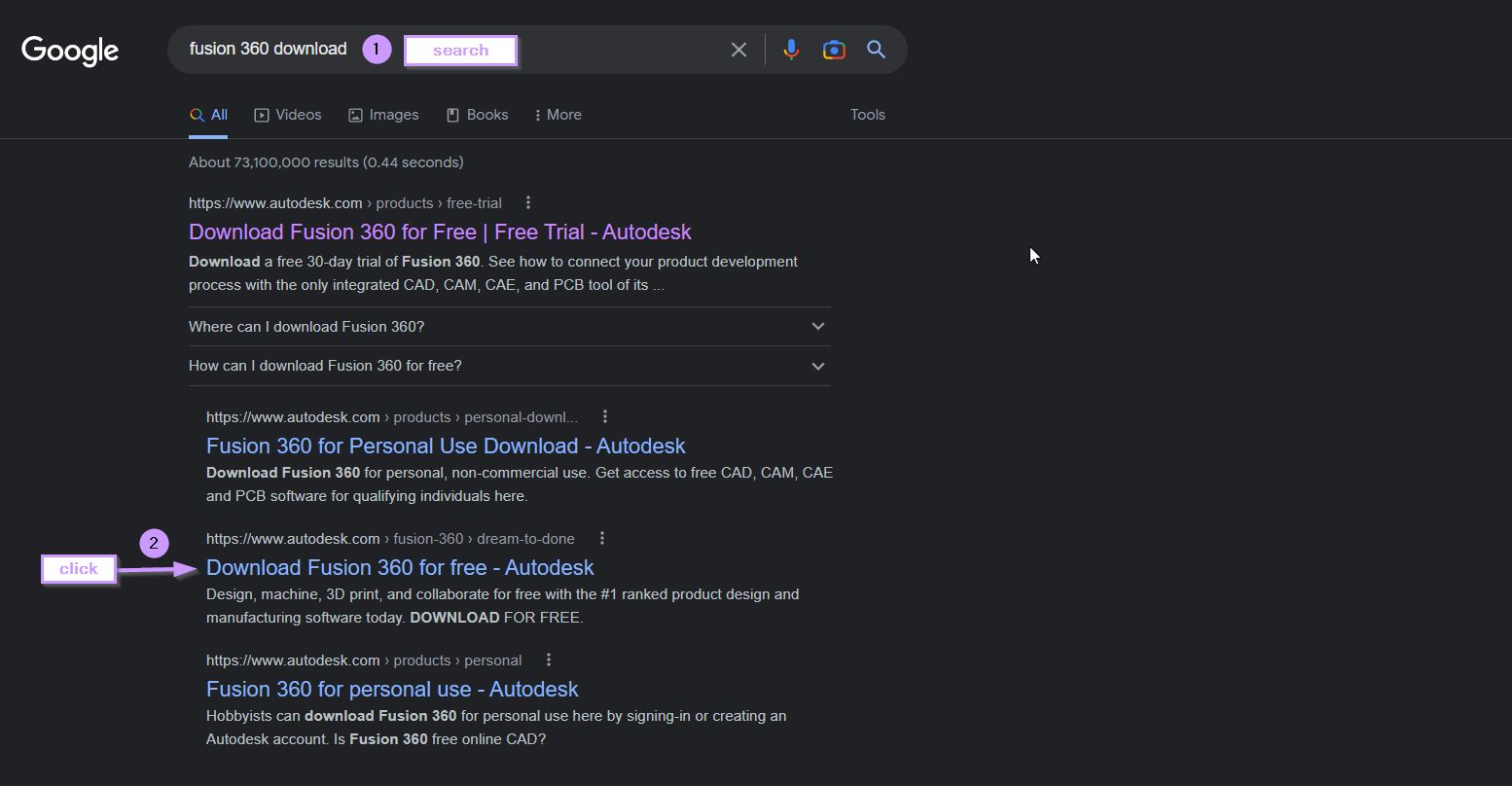
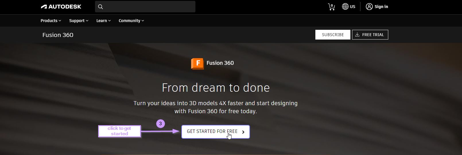
The steps to download Fusion 360:
1. Visit Fusion 360 website or search for it using the browser2. click on get started for free
3. sign up in the website and download the software
4. then open fusion 360 software and start Designing


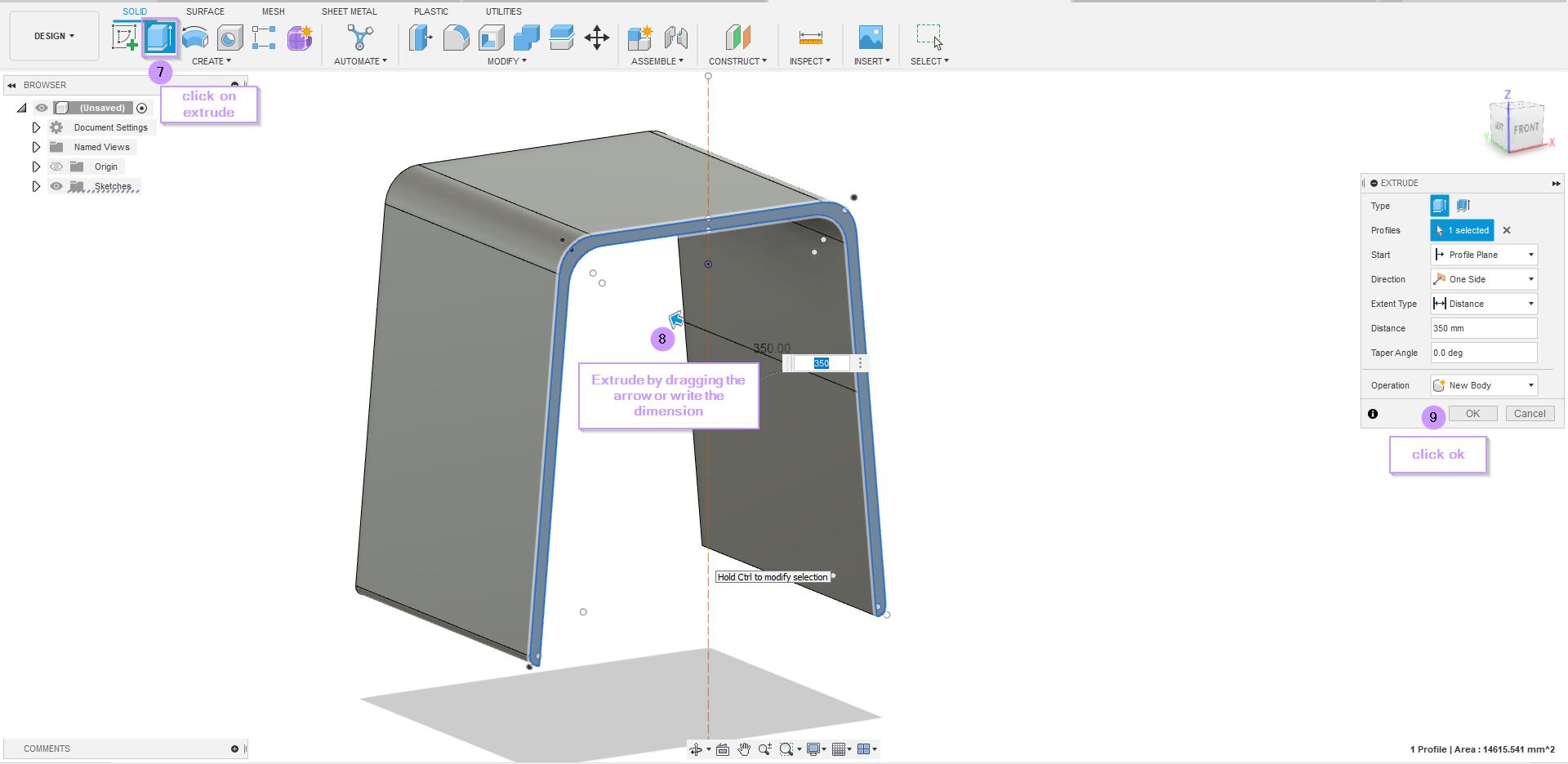
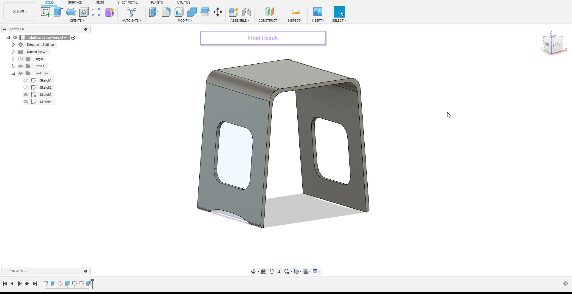
During this week i have managed to Design few objects using Fusion 360, the first Design was an in class activity where i had to mimic a chair as accurately as possible with the right measurements.
The steps to design the chair:
1. Open Fusion 3602. click on sketch and choose the front plane to design the sketch on
3. using the line, fillet, mirror and sketch dimension i have made the front view of the chair
4. Click on Extrude and then select the 2D design to extrude it based on the measurements
5. click on sketch and then select the left plane or side of the chair
6. draw a rectangle in the middle and fillet the corners
7. cick on extrude and drag it to the right side to create the cut in the middle


The Second design i made using fusion 360 is a Z-axis carriage for a project im working on which is designing a Z-axis for a multifunctional machine. The steps will be briefly discussed below along with an extended video tutorial that i made to show the exact steps carried while designing the Z-axis carriage.
The steps to design the Z-axis carriage:
1. Open Fusion 3602. click on sketch and choose the top plane to design the sketch on
3. Draw a polygon and extrude it
4. Draw another polygon that is smaller and extrude cut it
5. click on the front plane and sketch a square and fillet the corners while adding 4 circles at each corner > extrude it
6. repeat step 5 again on the back plane instead of front plane
7. extend the bottom of the polygon using push
8. select bottom plane and draw a rectangle and extrude it > fillet the corners
A video tutorial of the Z-axis carriage i made while creating the 3D module
The 3D view of the z axis carriage design
4. Exporting Files 
4.1 Method 1
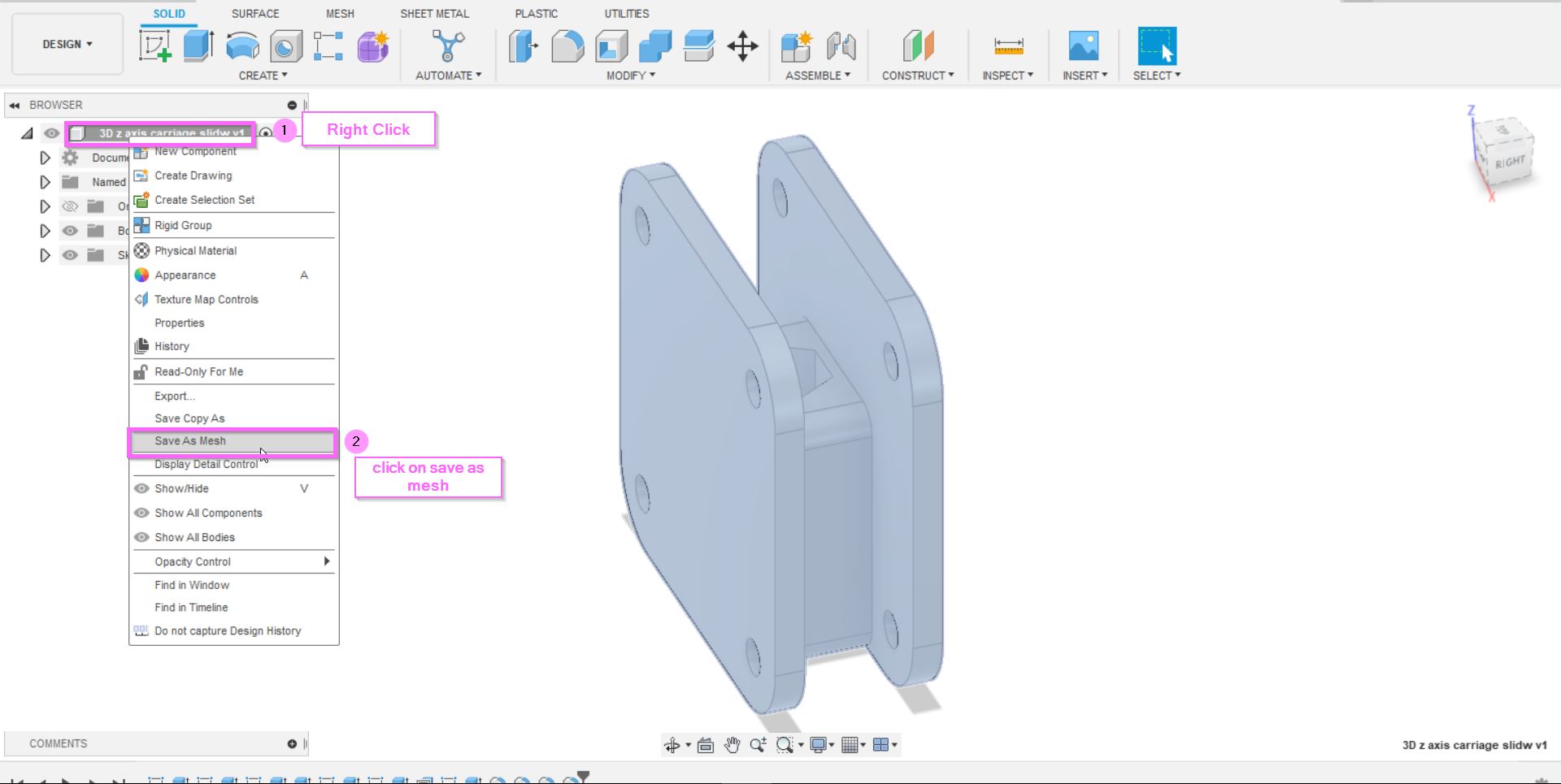
To export fusion 360 design Files:
1. Right click on the main folder that can be found at the top2. Click on save as mesh
3. Change the format to **STL (Binary)** and refinement to **High** > click ok
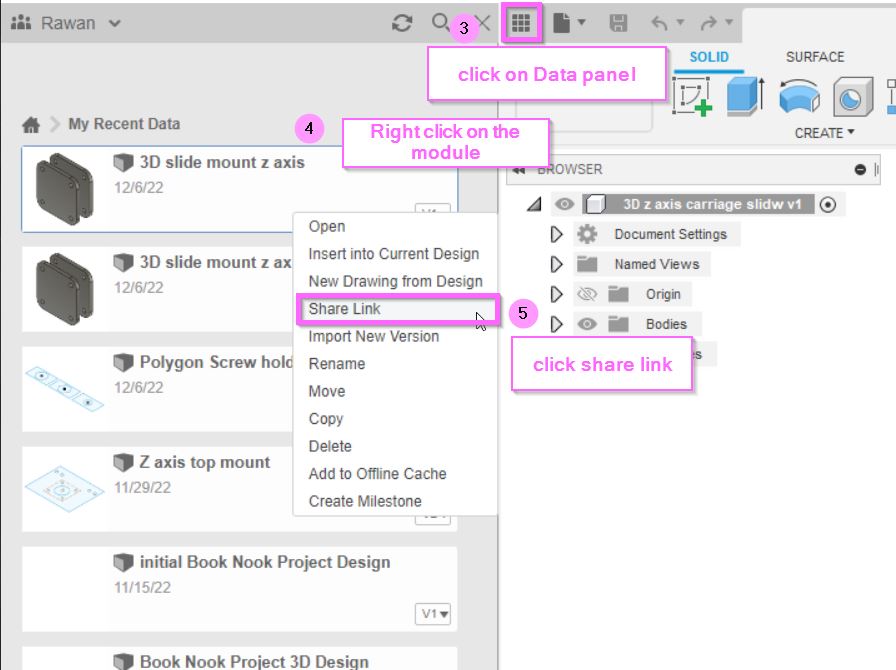
4. Click on the data panel (the icon with 9 square)
5. Right click on the design file you want to export
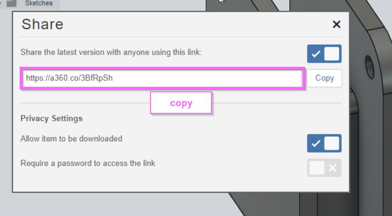
6. Click share link > tick "Share the latest version with anyone using the link" along with "Allow item to be downloaded"
7. Copy the link and paste it in the "PASTE YOUR LINK HERE" area found in the code shown below
<div class="fusion"><iframe width="640" height="480" src="PASTE YOUR LINK HERE" frameborder="0" allow="autoplay; fullscreen; vr" mozallowfullscreen="true" webkitallowfullscreen="true"></iframe> </div>

4.2 Method 2
To export design files using Sketchfab:
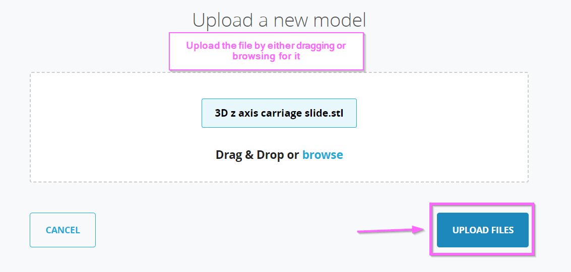
1. Visit Sketchfab website2. Click on upload at the top right corner
3. Drag or browse for the design file > click upload files
4. Write the Title of the design and description
5. Click on Free > save and publish
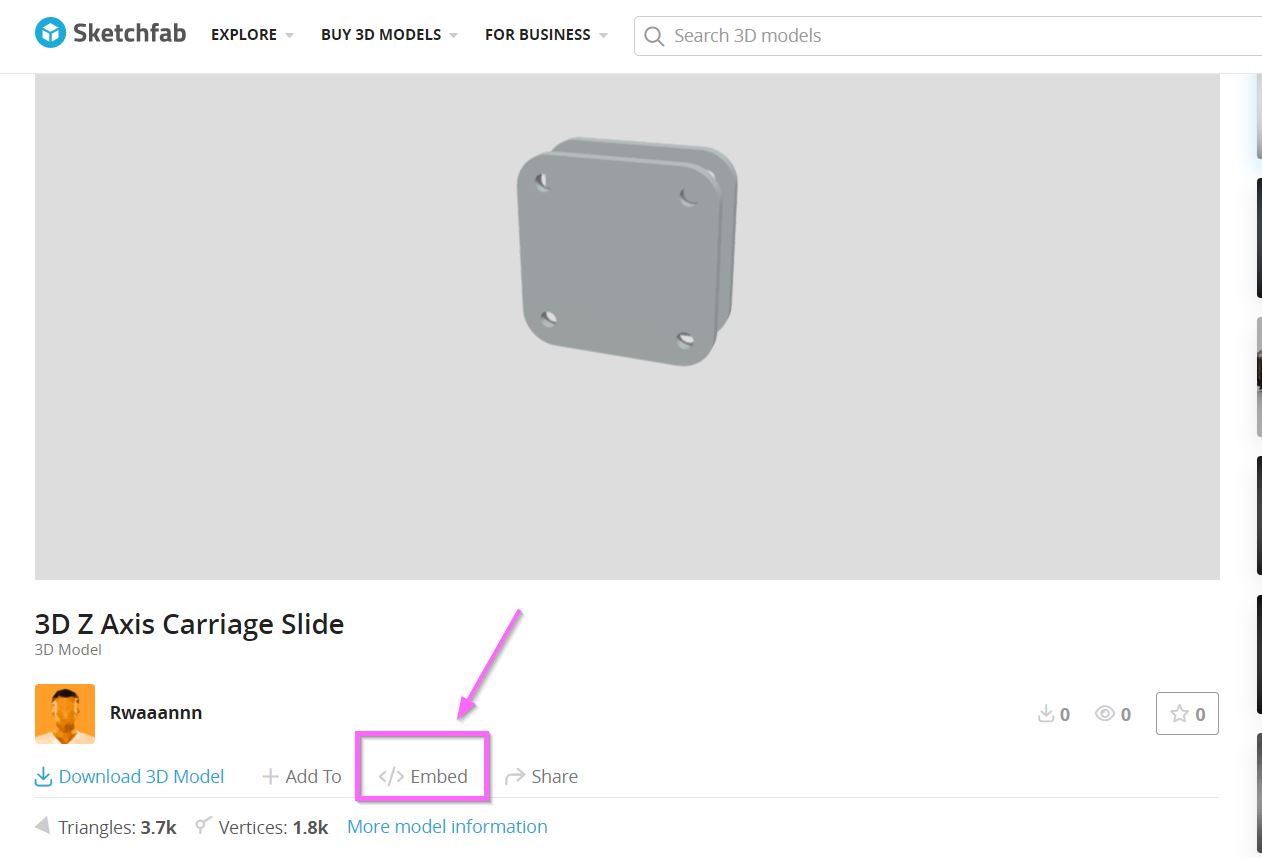
6. Click on view my model
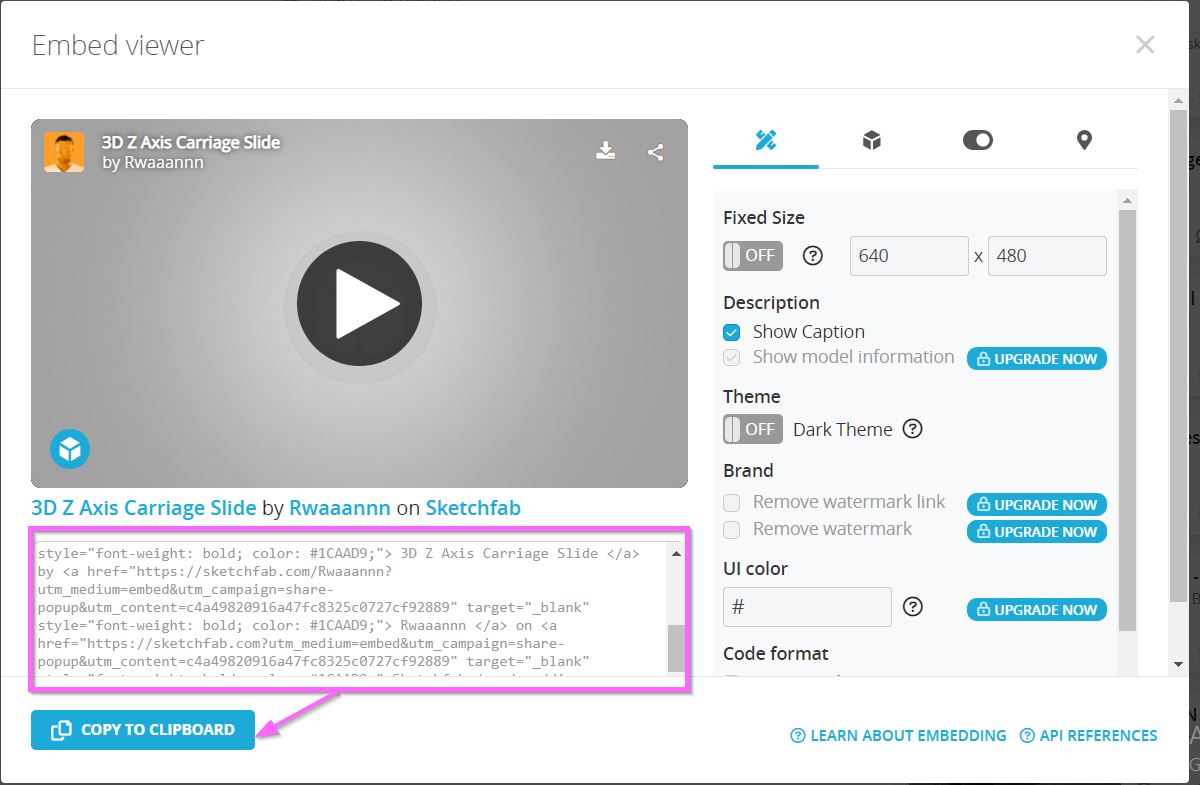
7. Click on embed > copy > paste it on the webpage


5. Conclusion 
During the second week of the program, i have managed to achieve the main aims and goals set, where i was able to try different softwares and programs used for both 2D and 3D designs. while working on the different softwares i have managed to design two 2D designs one using inkscape and the other using Cuttle, i personally liked both as they were great in their own ways, however, i enjoyed inkscape more as it had far more features and tools that allows the user to create different designs whether complex or simple. meanwhile, cuttle was great as well since it was extremely easy to operate and design yet feels limited in tools. For the 3D designs, i prefer using Fusion 360 over Tinkercad as it creates complex and far more detailed designs, however, i recommend using Tinkercad if you just want to prototype or have a better look on a specific design before getting into details in fusion as it helps you visualize how the design would look like in 3D.
6. Files
7. Useful links
- Fusion 360 Tips
- Fusion 360 beginner guide Tutorial
- Inkscape guide
- Cuttle guide
- TinkerCad
- Saving files in Fusion
- Free online Screen recording