4. Embedded programming
1. Introduction
2. Group Work
For the group work we did .... this and that… you can check the group assignment documentation on (website)
3. Individual Work
3.1 Microcontroller
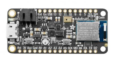
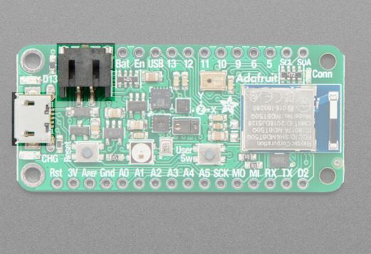
The microcontroller used during this week is Adafruit nRF52840 sense as it is equipped with different sensors as well as a Bluetooth low energy and a native USB support, in other words this microcontroller is “all in one” kind of microcontroller. this microcontroller comes with a Arduino IDE support which means it can be connected to an Arduino IDE software to create and run the code. Additionally, it works on circuit python as it is BLE-friendly as well as the fast Cortex and huge RAM.
Info
if you want to know more about the microcontroller visit Adafruit Feather nRF52840 sense
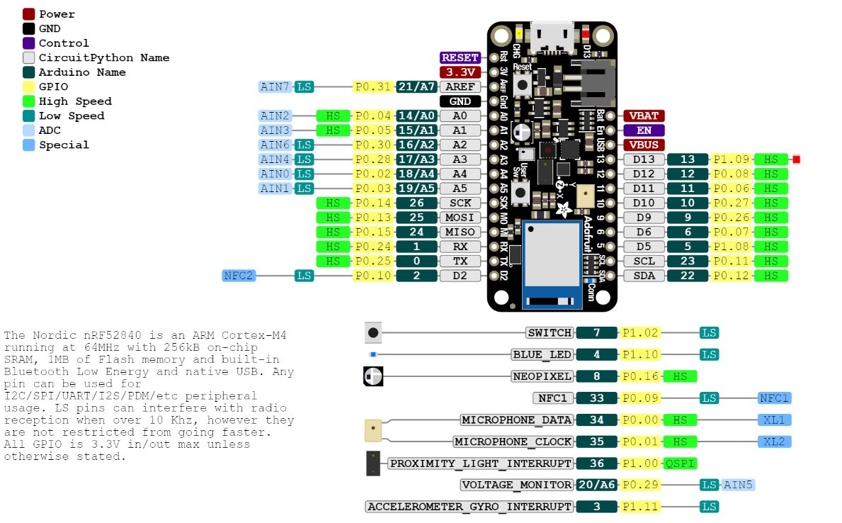
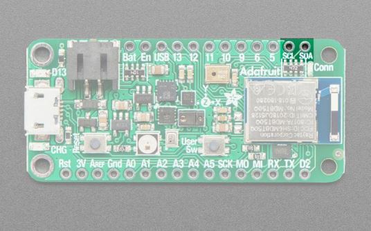
3.1.1 Pinouts
The Feather nRF52840 sense has a huge number of pins and sensor incorporated within its tiny body, therefore, i will be discussing the ones i used during this week along with the important pins.
Power Pins
- 3V - This pin is linked to the 3.3V regulator’s output on the board. It can be utilized to provide 3.3V power to FeatherWings, breakouts, or external sensors.
- GND - the common channel in an electrical circuit where all voltages may be monitored or the reference point for all signals
- USB Power (USB) - The voltage supplied directly from the USB connector to a laptop or anything else, usually the voltage ranges from 4.5-5.2V
Analog Pins
-
A0-A5 - The Analogs from A0-A5 can be coded or arranged to generate 8, 10 or 12-bit data at a speed up to 200kHz
-
AREF - can be utilized as an optional external analog reference for the internal comparator (COMP) peripheral.
Warning
To avoid damaging the analog circuitry, ensure that the AREF MUST either be equal or lower than VDD (3.3V)
PWM Outputs & I2C Pins
- PMW Outputs - is a method of obtaining analog outcomes via digital means. Three PWM modules may give up to 12 PWM channels with independent frequency control in groups of four.
Note
Any GPIO pin can be configured as a PWM output, using the dedicated PWM block.
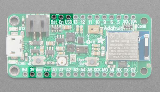
The shown below figure showcases the GPIO Pins (Highlighted in Yellow) and how to identify them. You can use any of these pins as PMW to make the connections.
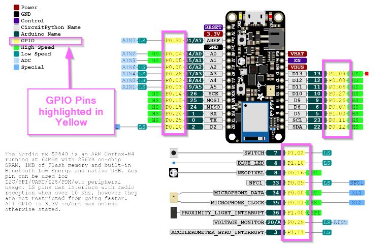
- I2C Pins - The nRF52840’s I2C pins have 4.7K pullup resistors added and are linked to Microphone sensors. for the microphone sensors Any other sensors can be connected as long as there is no I2C address clash.
USB & Battery
- USB Micro - The port is utilized to either supply power or aid in the programing of the feather sense. it is a typical USB Micro connection that can be connected to the laptop or pc.
- Battery - Because it features an inbuilt regulator and protective diodes, the Feather Sense may be powered by any 3V-6V power source. You may also use USB power to charge LiPoly batteries connected into this port.
Warning
Wrong polarity batteries will destroy the charging circuit. ENSURE that the batteries utilized are similar to Adafruit polarity
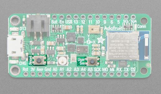
Buttons
-
Reset Button - The board is restarted by pressing the button on the left next to the USB port. To restart, press once. To enter the bootloader, quickly tap twice.
-
User Button - The button on the right is both bootloader- and user-controllable. Use board to address it in code. D7 in Arduino and SWITCH in CircuitPython.
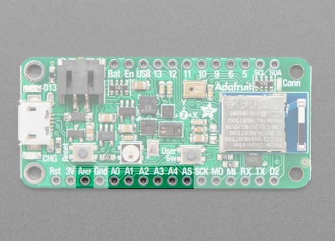
Button at left = Reset Button : Button at right = User Button
3.1.2 Power Management
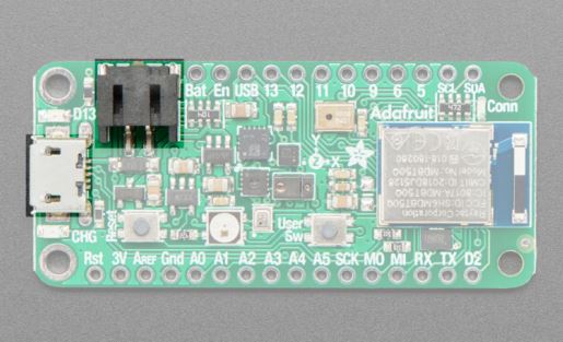
Battery + USB Power
The feather board can be supplied with power either using a computer (USB Source) or a battery source.
-
USB Source - using the cable connect it to a computer source to generate power, the microcontroller will regulate the 5V power source coming from the computer to reach 3.3V to match the board voltage intake.
-
Battery - you can either connect a Lithium Ion (Lilon) battery or a 4.2/3.7V lithium Polymer (LiPo/LiPoly). you can recharge the batteries.
Tip
in a case where the USB power is attached to a power source, it will directly switch to taking power from the USB, while charging up the battery. however, if the USB power source shuts down, the board will operate using the battery (LiPoly) power source as a back-up.
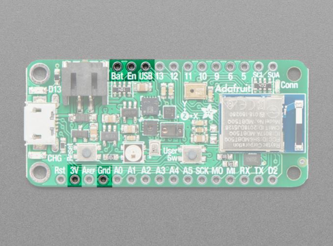
Left = Micro USB jack : Top left = LiPoly JST jack
Note
A CHG LED, located next to the USB jack, will blink when the battery is charging. It is common for this LED to blink if the battery is not attached.
Power Supplies
-
BAT pin - is linked to the LiPoly JST connection, as well as USB, which provides +5V if connected.
-
3V pin - has the output from the 3.3V regulator.
3.2 Arduino IDE
Arduino IDE Steps :
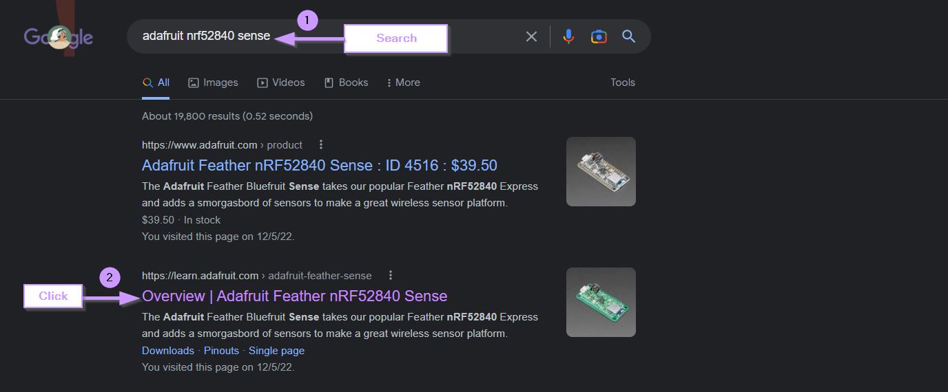
1. Search for "Adafruit nRF52840 sense"2. Click on the second link
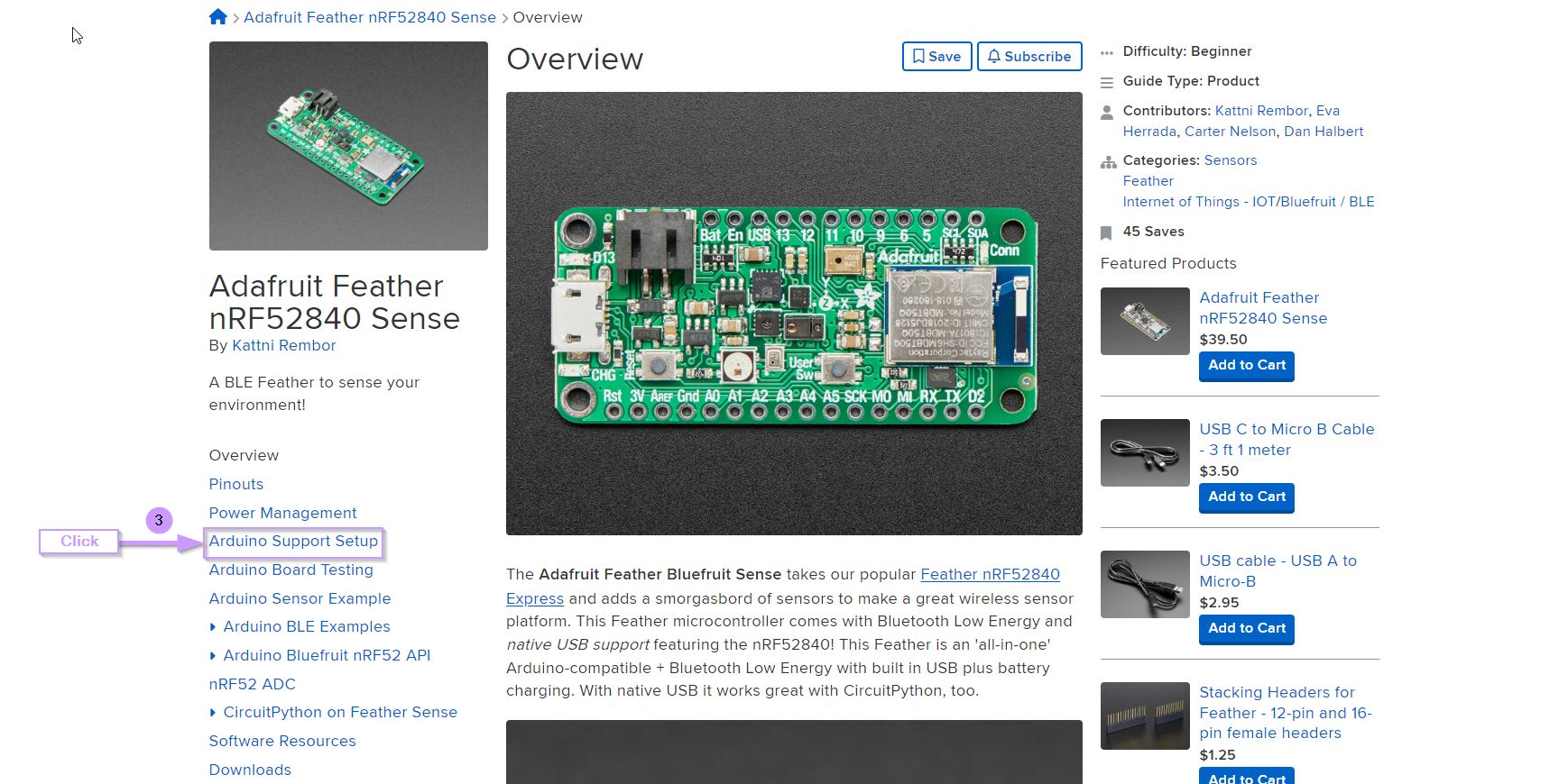
3. Click on "Arduino Support Setup"
4. Scroll a bit to find the link > Copy link
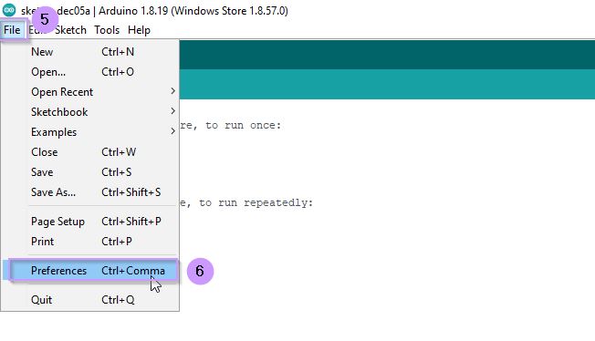
5. Open Arduino IDE software > File > Preferences
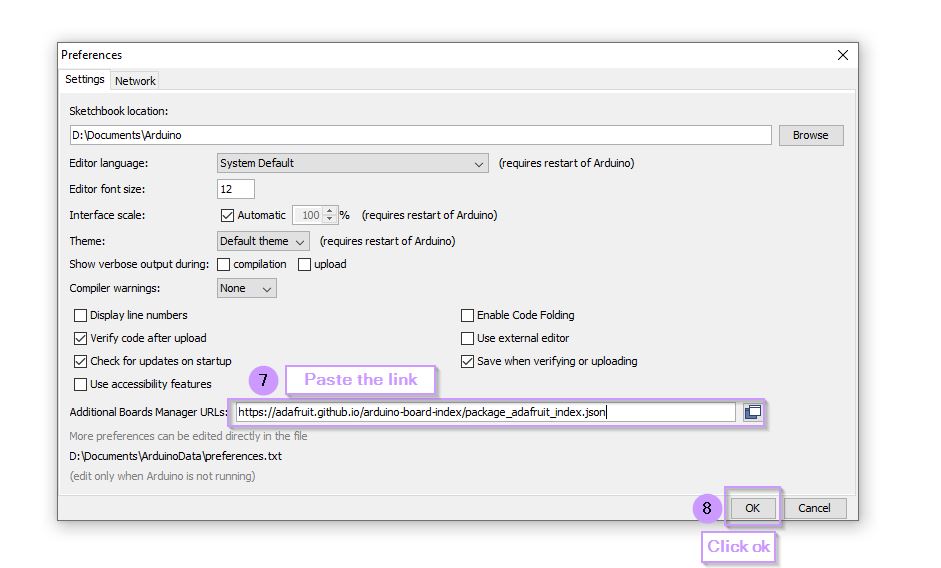
6. Paste the Link next to the URLs space > Click ok
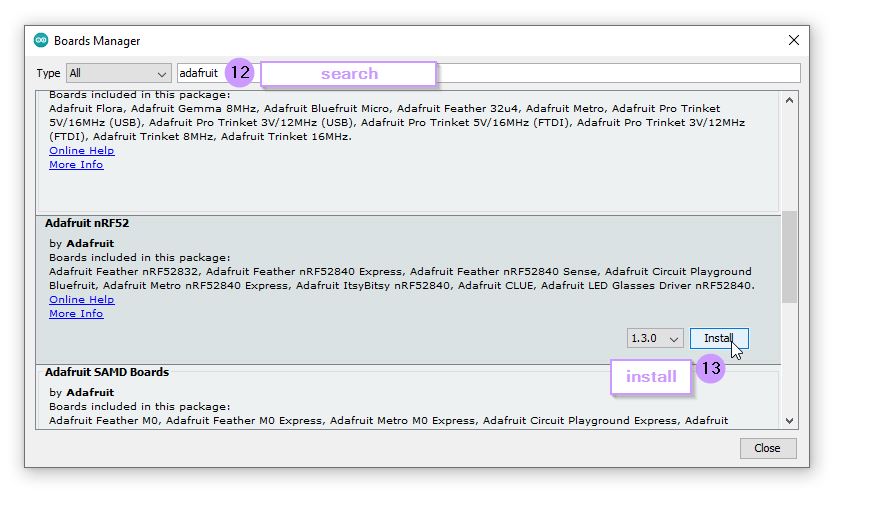
7. Tools > Board > Board Manager > Search "Adafruit"
8. Install Adafruit nRF52
9. Tools > Board > Adafruit nRF52 Boards> Adafruit feather nRF52840 Sense 10. Connect the microcontroller to the Laptop using USB cable
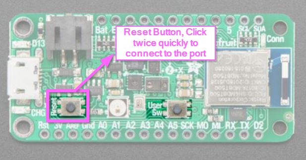
11. Tools > Port > Click twice on the reset button on the microcontroller (in order for the port connected to the microcontroller appears) > Click on the com connected to the board.
12. Start coding


Info
The reset button MUST be clicked twice quickly to successfully connect it to the port, once it is connected successfully a green light will blink on the board.
3.3 Blink Test
3.3.1 Arduino Blink Test
Blink Test Steps :
1. Open Arduino IDE software2. File > Examples > Basics > Blink
3. The code will appear on the page
4. Connect the boards and the port
5. Click Upload and wait for the sketch to upload
6. Once uploading is done, it will shown in the black inbox below "Uploaded successfully"
7. Try increasing the delay and reuploading

// the setup function runs once when you press reset or power the board
void setup() {
  // initialize digital pin LED_BUILTIN as an output.
  pinMode(LED_BUILTIN, OUTPUT);
}

// the loop function runs over and over again forever
void loop() {
  digitalWrite(LED_BUILTIN, HIGH);   // turn the LED on (HIGH is the voltage level)
  delay(1000);                       // wait for a second
  digitalWrite(LED_BUILTIN, LOW);    // turn the LED off by making the voltage LOW
  delay(1000);                       // wait for a second
}
Note
The delay in Arduino IDE is in milliseconds which explains why the delay is kept 1000. 1 second = 1000 milliseconds
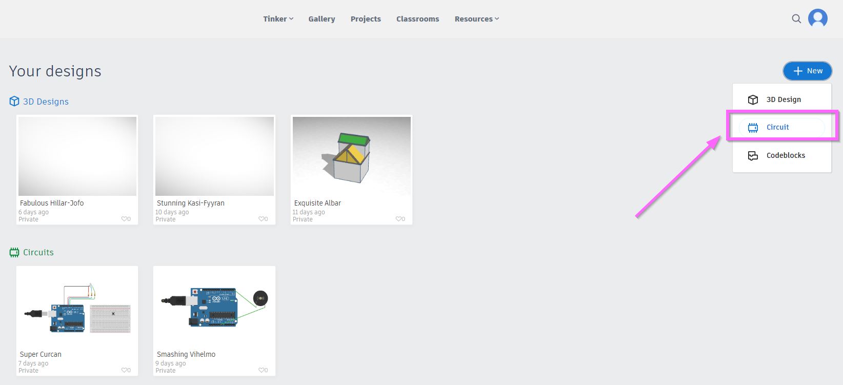
3.3.2 Tinkercad Blink Test
Blink Test Steps :
1. Visit Tinkercad website > Sign in > New > Circuit2. Click and Drag Arduino Uno
3. Click code
4. Change the Delay
5. Click start simulation
6. Try different delays
7. Try Repeat code, to repeat the number of blinks
// C++ code
//
int counter;

void setup()
{
  pinMode(LED_BUILTIN, OUTPUT);
}

void loop()
{
  for (counter = 0; counter < 5; ++counter) {
    digitalWrite(LED_BUILTIN, HIGH);
    delay(800); // Wait for 800 millisecond(s)
    digitalWrite(LED_BUILTIN, LOW);
    delay(600); // Wait for 600 millisecond(s)
  }
}
3.3.3 CircuitPython Blink Test
Blink Test Steps :
1. Visit Tinkercad website > Sign in > New > Circuit2. Click and Drag Arduino Uno
3. Click code
4. Change the Delay
5. Click start simulation
6. Try different delays
7. Try Repeat code, to repeat the number of blinks
"""Example for Pico. Blinks the built-in LED."""
import time
import board
import digitalio

led = digitalio.DigitalInOut(board.LED)
led.direction = digitalio.Direction.OUTPUT

while True:
    led.value = True
    time.sleep(0.5)
    led.value = False
    time.sleep(0.5)
The time.sleep is similar to delay in Arduino IDE, however the time is represented in seconds not milliseconds such as Arduino IDE
3.4 Morse Code Blink
In this task using the blinking code we should spell a word using Morse code, therefore whatever word or sentence we choose should be programmed in morse code as shown below. The word i chose for the Morse code is HELP. i will be programming the board using tinkercad which is an online circuit maker that is easy to use, not to mention you can upload the same code from tinkercad to an actual arduino uno or adafruit and it will work. the reason i chose to program it using tinkercad is due to the block feature which makes it easier and less confusing especially when writing a lengthy code with repeated commands.

// C++ code
//
int counter;

int counter2;

int counter3;

void setup()
{
  pinMode(LED_BUILTIN, OUTPUT);
}

void loop()
{
  for (counter = 0; counter < 4; ++counter) {
    digitalWrite(LED_BUILTIN, HIGH); //
    delay(1000); // Wait for 1000 millisecond(s)
    digitalWrite(LED_BUILTIN, LOW);
    delay(500); // Wait for 500 millisecond(s)
  }
  digitalWrite(LED_BUILTIN, LOW);
  delay(3000); // Wait for 3000 millisecond(s)
  digitalWrite(LED_BUILTIN, HIGH);
  delay(1000); // Wait for 1000 millisecond(s)
  digitalWrite(LED_BUILTIN, LOW);
  delay(3000); // Wait for 3000 millisecond(s)
  digitalWrite(LED_BUILTIN, HIGH);
  for (counter2 = 0; counter2 < 2; ++counter2) {
    digitalWrite(LED_BUILTIN, HIGH);
    delay(1000); // Wait for 1000 millisecond(s)
    digitalWrite(LED_BUILTIN, LOW);
    delay(500); // Wait for 500 millisecond(s)
  }
  delay(3000); // Wait for 3000 millisecond(s)
  digitalWrite(LED_BUILTIN, HIGH);
  delay(1000); // Wait for 1000 millisecond(s)
  digitalWrite(LED_BUILTIN, LOW);
  delay(500); // Wait for 500 millisecond(s)
  for (counter3 = 0; counter3 < 2; ++counter3) {
    digitalWrite(LED_BUILTIN, HIGH);
    delay(2000); // Wait for 2000 millisecond(s)
    digitalWrite(LED_BUILTIN, LOW);
    delay(500); // Wait for 500 millisecond(s)
  }
  digitalWrite(LED_BUILTIN, HIGH);
  delay(1000); // Wait for 1000 millisecond(s)
  digitalWrite(LED_BUILTIN, LOW);
  delay(5000); // Wait for 5000 millisecond(s)
}
The simulation of morse code blinking using Tinkercad, the word is HELP
4. Conclusion
To conclude, i have managed to learn a lot about microcontroller boards and how the operate, especially featherwing nRF52840 sense that i will using for the upcoming weeks. with the help of the data sheet of the board i was able to understand more and locate each pin and what it does. Moreover, we have been introduced to 3 different code programing softwares/website that can aid in writing the commands for the board.