Final Project
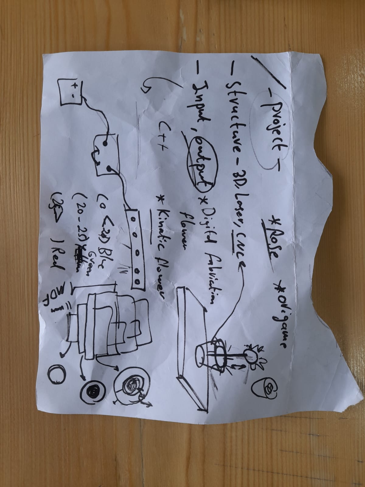
This week we worked on defining our final project “Smart Object” and started to getting used to the documentation process.
-
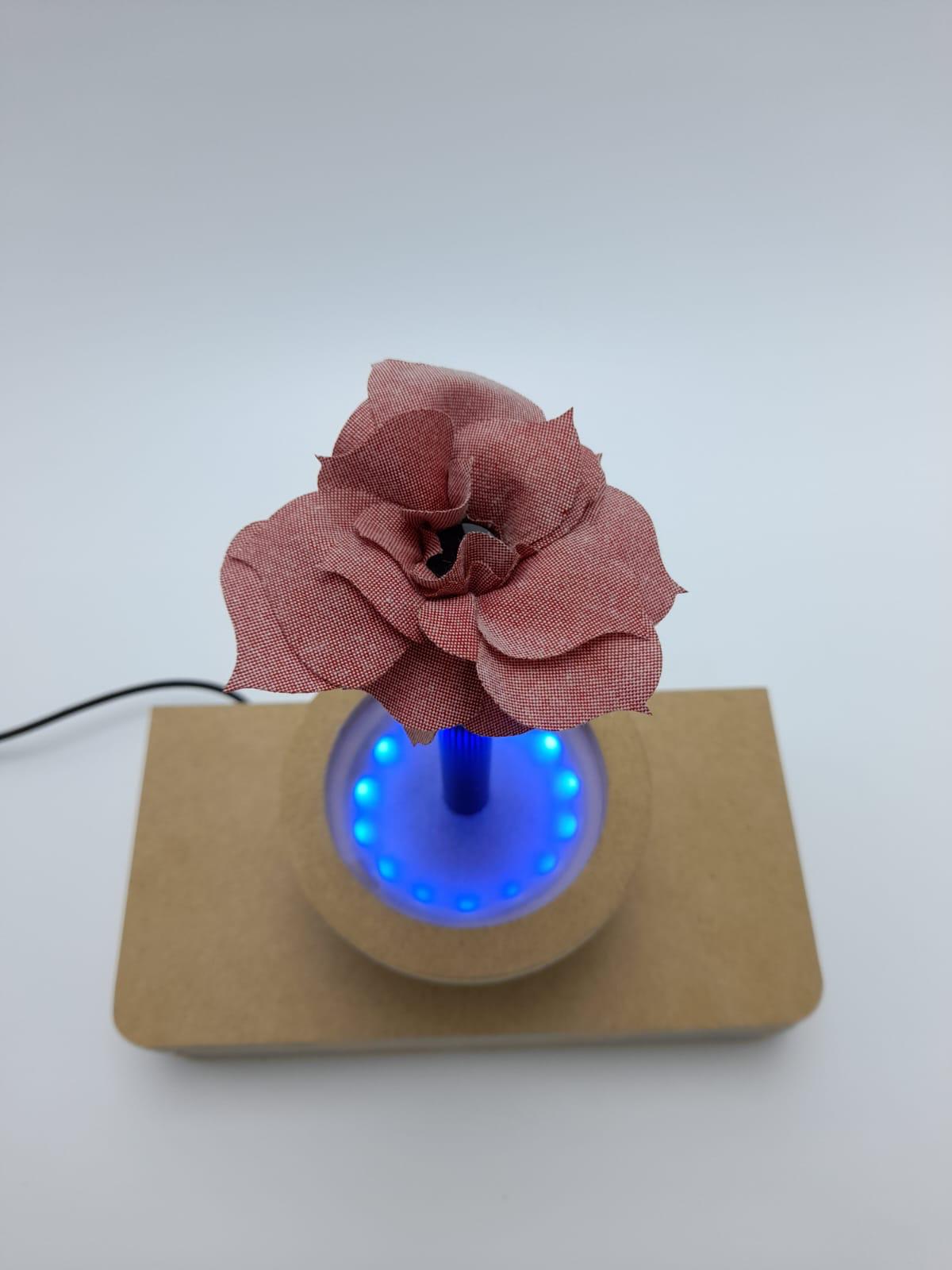
The project is a smart object so that it receives input and gives output. There is another project, which is a smart shelf. If you approach it, it reads the temperature of the place and sends it to our object, and according to the temperature of the place, the color lights up.
-
What I want here is to make the LED light up in different colors depending on the temperature.
-
You can see the design of the pot in Mohammed’s page.
-
Design of the petals and how we connection the flower with the servo in Hamed’s page.
-
For the servo motor code and how did we connect it to the petals you can visit Ayman’s page.
Research.
- From my side, I was working on the code for the object, so I was working on turning on the LED addresble through the Arduino program..
What is Arduino?.
-
Arduino is an open-source electronics platform based on easy-to-use hardware and software. Arduino boards are able to read inputs - light on a sensor, a finger on a button, or a Twitter message - and turn it into an output - activating a motor, turning on an LED, publishing something online. You can tell your board what to do by sending a set of instructions to the microcontroller on the board. To do so you use the Arduino programming language (based on Wiring), and the Arduino Software (IDE), based on Processing.
-
For download
-
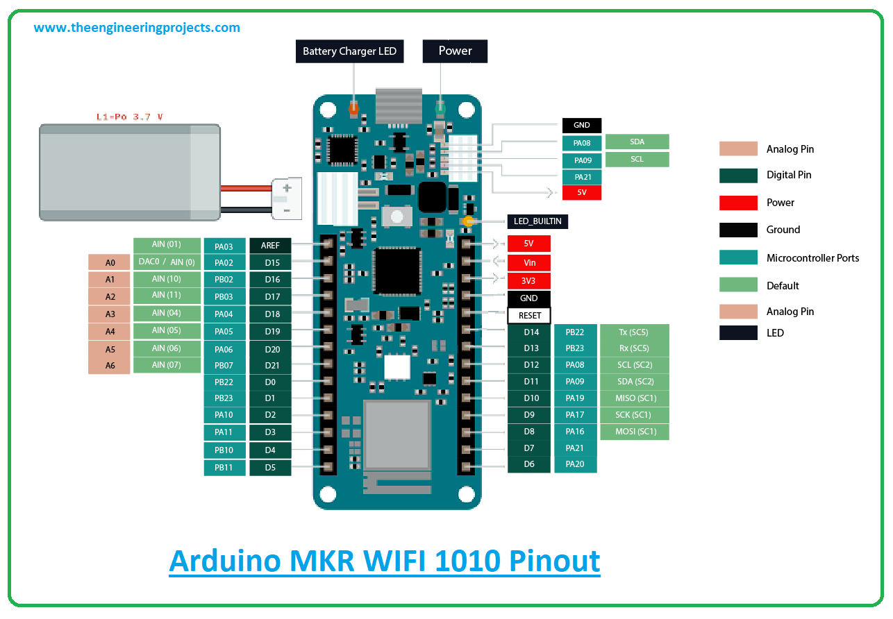
Arduino MKR wifi 1010: The MKR WiFi 1010 is a miniature sized modulecontaining a SAMD21G18A Processor, the NinaW102 Module, a crypto chip (the ATECC508), and a2MByte SPI Flash.
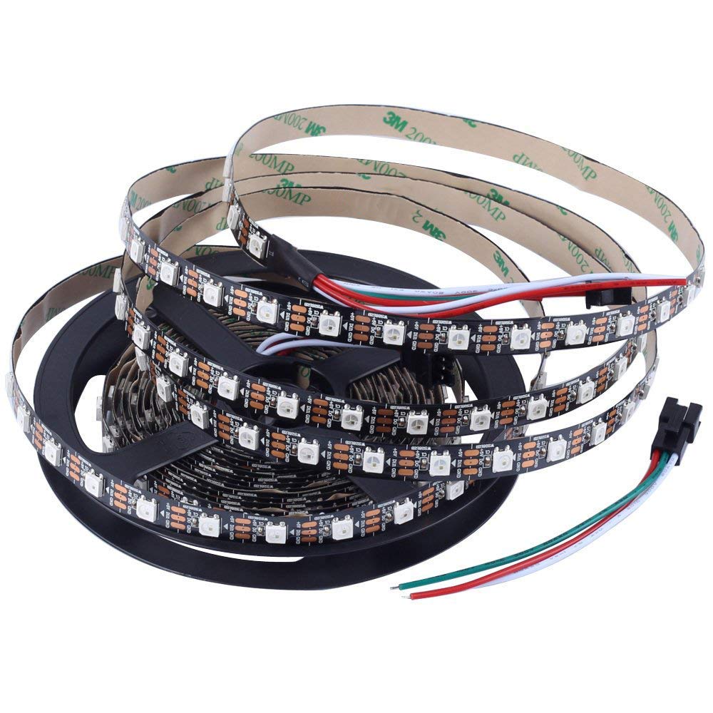
What is Addressable LED?
- Addressable LED strips are light strips that have unique chips that allow you to control individual LEDs or groups of them. This extra provision to control a specific part of the strip is why they are referred to as ‘addressable’.
How it’s work?
Individually addressable LEDS have a tiny microcontroller on each of the LEDs to allows each one to light up with a unique color and brightness. The strips have a positive voltage wire, a ground, and a data wire. Each time the data reaches an led it is read and passed down the strip to the next led.
The code.
-
I searched for a long time for a code that works with the LED and how to connect it correctly, and I found this website and it was very suitable with following these step below.
-
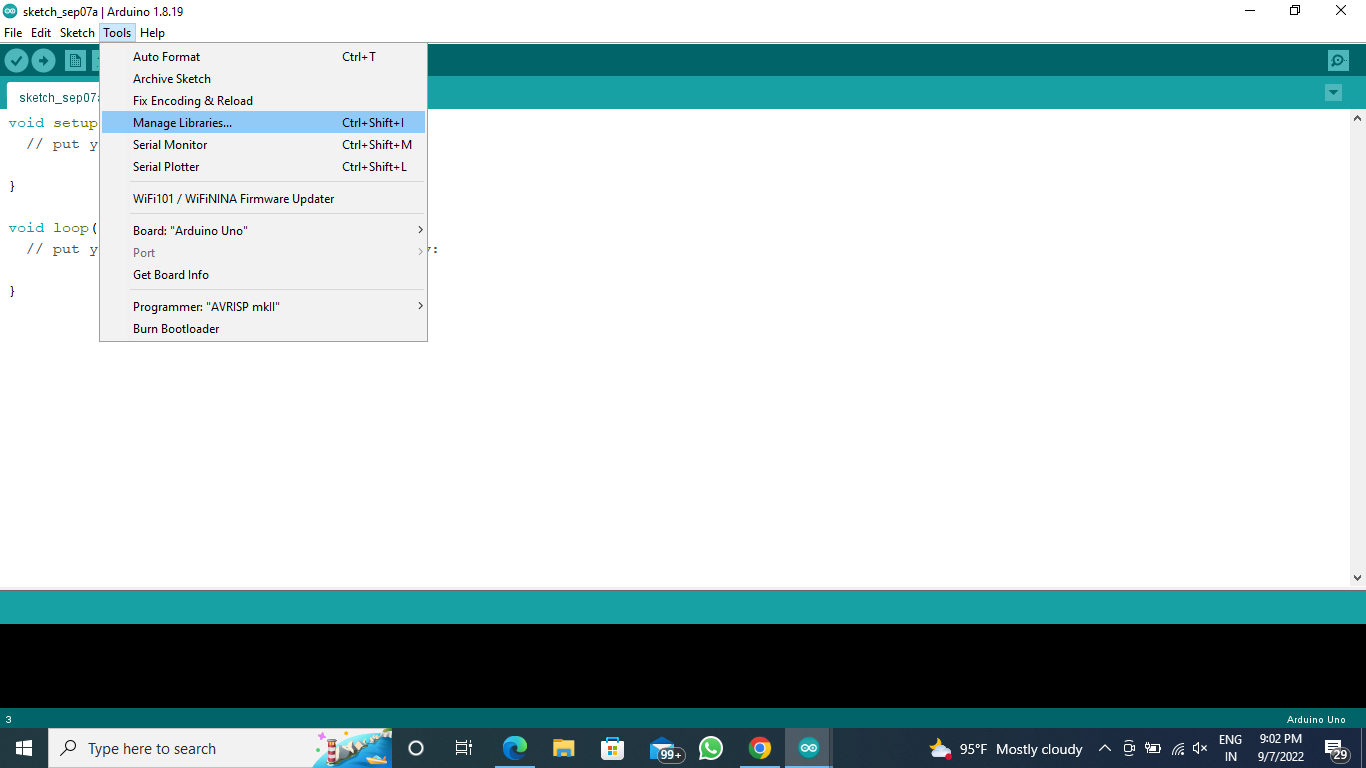
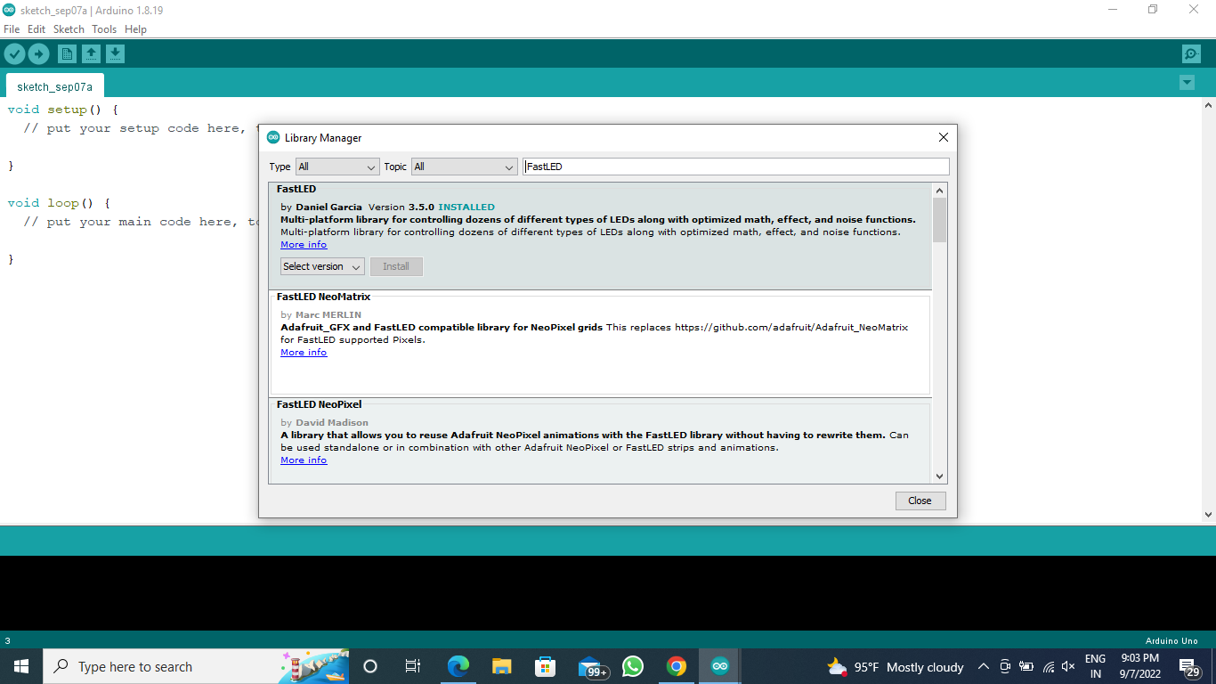
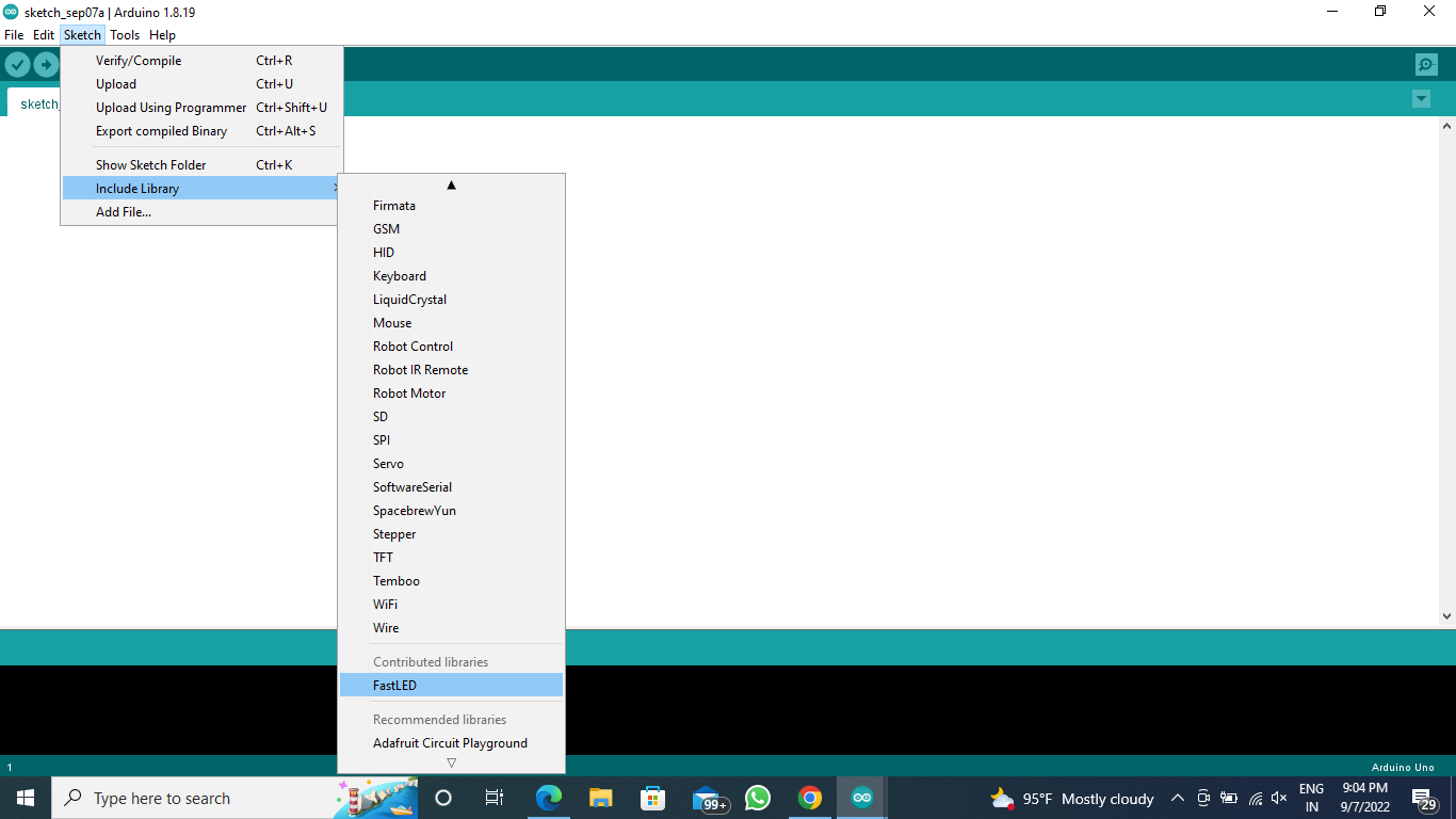
First, I downloaded the FastLED library.
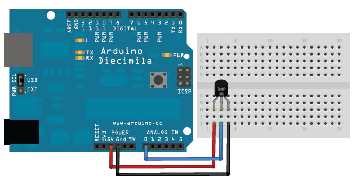
- The temperature sensor in Arduino converts the surrounding temperature to voltage. It further converts the voltage to Celcius, Celcius to Fahrenheit, and prints the Fahrenheit temperature on the LCD screen.
- I modified the code below to make it compatible with the temperature sensor.
#include <FastLED.h>
#define LED_PIN 2
#define NUM_LEDS 12

CRGB leds[NUM_LEDS];

void setup() {
  FastLED.addLeds<WS2812, LED_PIN, GRB>(leds, NUM_LEDS);
  FastLED.setMaxPowerInVoltsAndMilliamps(5, 500);
  FastLED.clear();
  FastLED.show();

}

void loop() {
  // RED Green Blue
for (int i=0; i<NUM_LEDS; i++ )
{
    leds[i] = CRGB(0, 255-2*i, 20*i );
    FastLED.setBrightness(6*i);
    FastLED.show();
    delay (50);
}
for (int i=NUM_LEDS; i> 0; i-- )
{
    leds[i] = CRGB(20*i, 0, 255-20*i );
    FastLED.setBrightness(60-2*i);
    FastLED.show();
        delay (50);

}
}
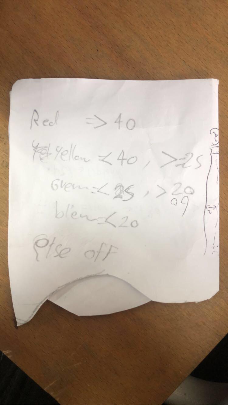
- This is the temperature condition we want it.
-
This code is modified according to the conditions we want also add the code of the servo from my colleague Ayman.
-
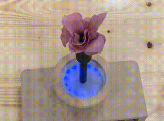
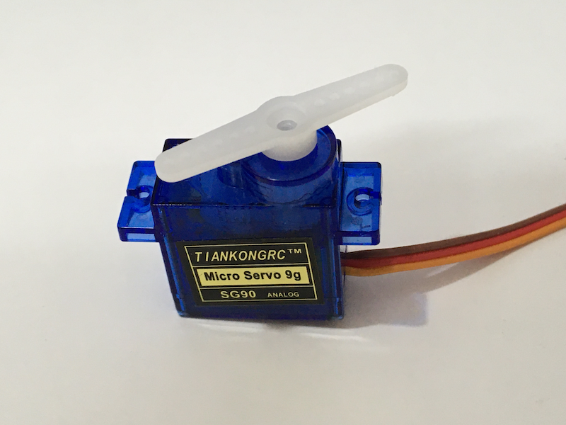
We used the servo here to make the rose move.
How does a servo motor work?
- A servo motor is an electromechanical device that produces torque and velocity based on the supplied current and voltage. A servo motor works as part of a closed loop system providing torque and velocity as commanded from a servo controller utilizing a feedback device to close the loop.
- This code moves the flower through the servo and then provides the opportunity to turn on the LED according to the recorded temperature.
#include <FastLED.h>
#include <Servo.h>
#define LED_PIN 4
#define NUM_LEDS 14
CRGB leds[NUM_LEDS];
int temp = 15;
int time = 100;
Servo myservo;  // create servo object to control a servo
// twelve servo objects can be created on most boards
 #define sensor 8
int pos = 0;    // variable to store the servo position

void setup() {
  FastLED.addLeds<WS2812, LED_PIN, GRB>(leds, NUM_LEDS);
  FastLED.setMaxPowerInVoltsAndMilliamps(5, 500);
  FastLED.clear();
  FastLED.show();
  myservo.attach(5);

}

void loop() {

float Temp_c = temp;

  if(digitalRead(sensor) == HIGH && pos == 0){
      for (pos = 0; pos <= 200; pos += 1) { // goes from 0 degrees to 180 degrees
      // in steps of 1 degree
      myservo.write(pos);              // tell servo to go to position in variable 'pos'
      delay(15);                       // waits 15 ms for the servo to reach the position
      }
      pos = 200;
    }else if(digitalRead(sensor) == LOW && pos == 200){

  for (pos = 200; pos >= 0; pos -= 1) { // goes from 180 degrees to 0 degrees
    myservo.write(pos);              // tell servo to go to position in variable 'pos'
    delay(15);                       // waits 15 ms for the servo to reach the position
  }
      pos = 0;}

if (Temp_c >= 40.0){
  // RED Green Blue
for (int i=0; i<NUM_LEDS; i++ )
{
    leds[i] = CRGB( 255-2*i, 0, 0 );
    FastLED.setBrightness(6*i);
    FastLED.show();
    delay (time);
}
for (int i=NUM_LEDS; i> 0; i-- )
{
    leds[i] = CRGB(255-20*i,0, 0 );
    FastLED.setBrightness(6*i);
    FastLED.show();
        delay (time);

}}

else if(Temp_c < 40 && Temp_c >= 25){
for (int i=0; i<NUM_LEDS; i++ )
{
    leds[i] = CRGB( 255-2*i, 255-2*i, 0 );
    FastLED.setBrightness(6*i);
    FastLED.show();
    delay (time);
}

for (int i=NUM_LEDS; i> 0; i-- )
{
    leds[i] = CRGB(255-20*i, 255-20*i, 0 );
    FastLED.setBrightness(6*i);
    FastLED.show();
        delay (time);

}}

else if (Temp_c < 25 && Temp_c > 20){
for (int i=0; i<NUM_LEDS; i++ )
{
    leds[i] = CRGB( 0, 255-2*i, 0 );
    FastLED.setBrightness(6*i);
    FastLED.show();
    delay (time);
}
for (int i=NUM_LEDS; i> 0; i-- )
{
    leds[i] = CRGB(0, 255-20*i, 0 );
    FastLED.setBrightness(6*i);
    FastLED.show();
        delay (time);

}}

else if(Temp_c < 20)
{
for (int i=0; i<NUM_LEDS; i++ )
{
    leds[i] = CRGB( 0, 0, 255-2*i );
    FastLED.setBrightness(6*i);
    FastLED.show();
    delay (time);
}
for (int i=NUM_LEDS; i> 0; i-- )
{
    leds[i] = CRGB(0, 0, 255-20*i );
    FastLED.setBrightness(6*i);
    FastLED.show();
        delay (time);

}}

else {
for (int i=NUM_LEDS; i> 0; i-- )
{
    leds[i] = CRGB(0, 0, 0 );
    FastLED.setBrightness(60-2*i);
    FastLED.show();
        delay (time);

}}}
- Try the second condition.
- Try the fourth condition.
- color changed with the temperature.
The Problems.
- Some of the problems that we faced is that the LED was soldered opposite to the signal, which made it not light up and we solved the problem by re-soldering it again and this was my first experience.
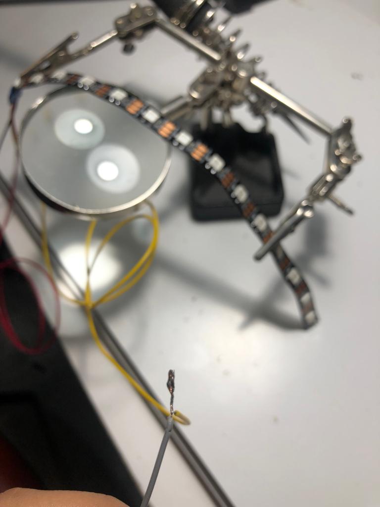
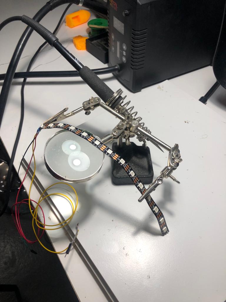
- Before soldered.
- The second problem was that my laptop was damaged, which made me retype the code on a colleague’s laptop.
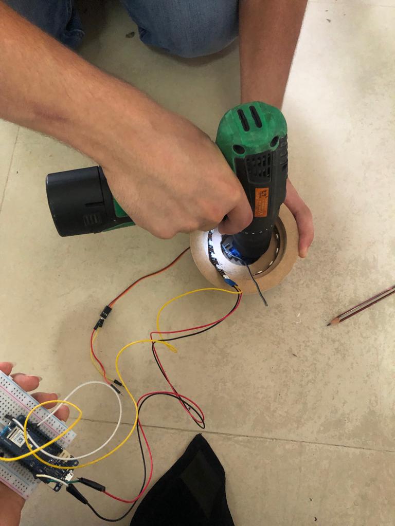
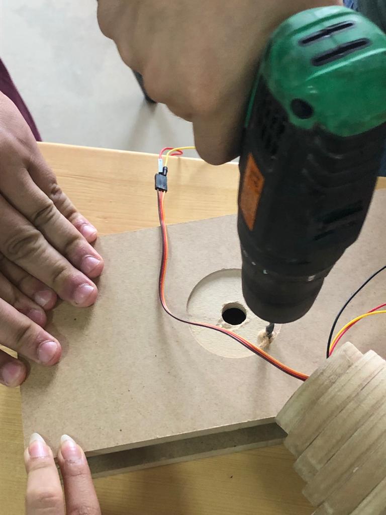
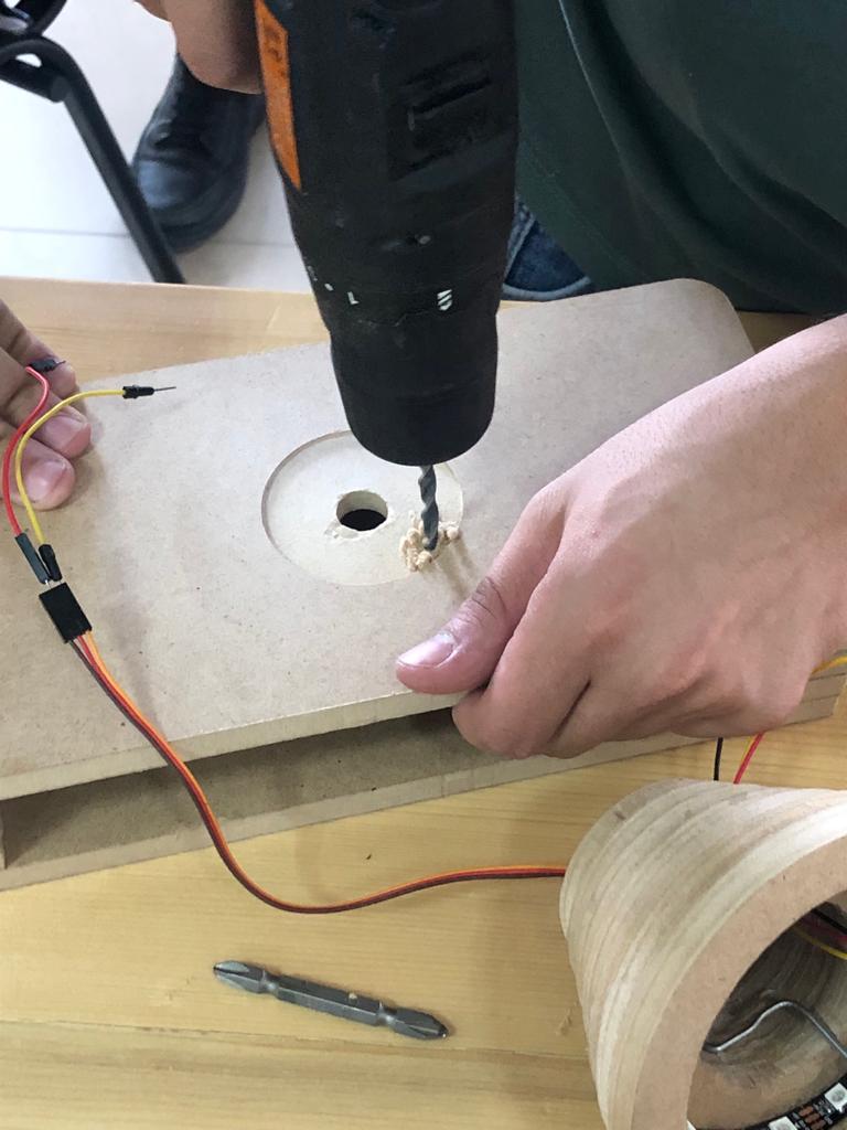
Add LED in the pot.
- We made a small hole in the pot so that we could insert the LED through it.
Final Result.