Final Project
For my project I decided to make a self stabilizing platform, using servos and a gyro scope to keep a plat form level, or keep the plat form on a specific angle (offset from level).
2D and 3D Modeling
to start I needed to design two arms, one platform, and a base which is completed with a box.
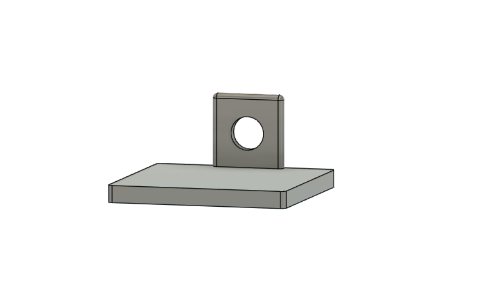
first I made a simple box
then I made a hole for the servo by using a premade model of the servo I’m using
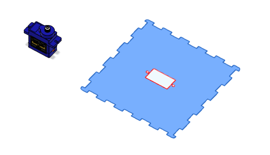
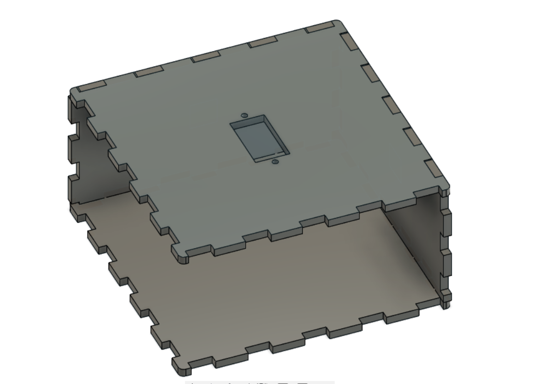
then I finished the box
then I made an arm
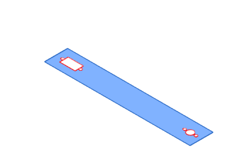
and I used the same parameters of the servo hole from previous design
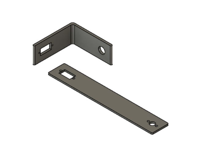
of Couse I made two of different lengths so they don’t interfere with each other when rotating.
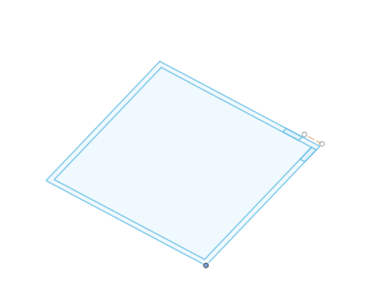
and for the platform
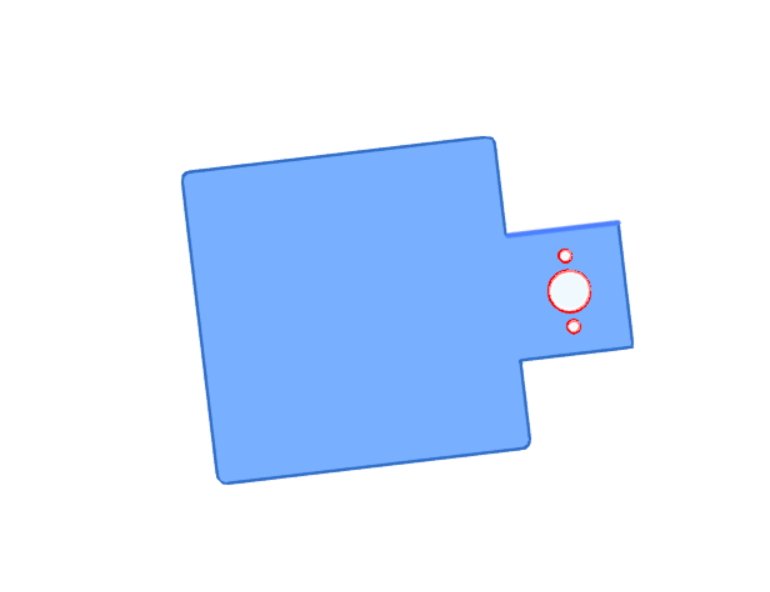
notice that Im making 3D models and a flat 2D model in fact we wont be using the 3D model its only for demonstration here, because Im going to cut my design with the laser cutter from acrylic and bend it. but I will add both 3D design files as well as 2D, so you can choose either to 3D print it (sense its more available) or use the 2D design files with the laser cutter and bend it.
3D files:
base f3d,
stl
Arm f3d,
stl
platform f3d,
stl
2D Files:
Box Top
Box bottom
arm 1
arm 2
side 1 x2
side 2 x2
platform
cutting the parts with the laser cutter
I got the parts and I went to bend them in shape
Code
as for the code read the comments to understand what to do
  // Full orientation sensing using NXP/Madgwick/Mahony and a range of 9-DoF
// sensor sets.
// You *must* perform a magnetic calibration before this code will work.
//
// To view this data, use the Arduino Serial Monitor to watch the
// scrolling angles, or run the OrientationVisualiser example in Processing.
// Based on  https://github.com/PaulStoffregen/NXPMotionSense with adjustments
// to Adafruit Unified Sensor interface

#include <Adafruit_Sensor_Calibration.h>
#include <Adafruit_AHRS.h>

#include <Adafruit_APDS9960.h>
#include <Adafruit_BMP280.h>
#include <Adafruit_LIS3MDL.h>
#include <Adafruit_LSM6DS33.h>
#include <Adafruit_SHT31.h>
#include <Adafruit_Sensor.h>
#include <PDM.h>
#include <Servo.h>

Servo servo0;
Servo servo1;
Servo servo2;
int j=0;
int tes=1;
int correct;
int correct2;
int trash;
float offsetroll;
float offsetpitch;

Adafruit_Sensor *accelerometer, *gyroscope, *magnetometer;

// uncomment one combo 9-DoF!
#include "LSM6DS_LIS3MDL.h"  // can adjust to LSM6DS33, LSM6DS3U, LSM6DSOX...
//#include "LSM9DS.h"           // LSM9DS1 or LSM9DS0
//#include "NXP_FXOS_FXAS.h"  // NXP 9-DoF breakout

// pick your filter! slower == better quality output
Adafruit_NXPSensorFusion filter; // slowest
//Adafruit_Madgwick filter;  // faster than NXP
//Adafruit_Mahony filter;  // fastest/smalleset

#if defined(ADAFRUIT_SENSOR_CALIBRATION_USE_EEPROM)
  Adafruit_Sensor_Calibration_EEPROM cal;
#else
  Adafruit_Sensor_Calibration_SDFat cal;
#endif

#define FILTER_UPDATE_RATE_HZ 100
#define PRINT_EVERY_N_UPDATES 10
//#define AHRS_DEBUG_OUTPUT

uint32_t timestamp;

void setup() {
  Serial.begin(115200);
  Serial.setTimeout(50);
  //while (!Serial) yield();

  if (!cal.begin()) {
    Serial.println("Failed to initialize calibration helper");
  } else if (! cal.loadCalibration()) {
    Serial.println("No calibration loaded/found");
  }

  if (!init_sensors()) {
    Serial.println("Failed to find sensors");
    while (1) delay(10);
  }

  accelerometer->printSensorDetails();
  gyroscope->printSensorDetails();
  magnetometer->printSensorDetails();

  setup_sensors();
  filter.begin(FILTER_UPDATE_RATE_HZ);
  timestamp = millis();

  Wire.setClock(400000); // 400KHz

  servo0.attach(10);
  servo1.attach(9);
  servo2.attach(6);
}


void loop() {
  float roll, pitch, heading;
  float gx, gy, gz;
  static uint8_t counter = 0;

  if ((millis() - timestamp) < (1000 / FILTER_UPDATE_RATE_HZ)) {
    return;
  }
  timestamp = millis();
  // Read the motion sensors
  sensors_event_t accel, gyro, mag;
  accelerometer->getEvent(&accel);
  gyroscope->getEvent(&gyro);
  magnetometer->getEvent(&mag);
#if defined(AHRS_DEBUG_OUTPUT)
  Serial.print("I2C took "); Serial.print(millis()-timestamp); Serial.println(" ms");
#endif

  cal.calibrate(mag);
  cal.calibrate(accel);
  cal.calibrate(gyro);
  // Gyroscope needs to be converted from Rad/s to Degree/s
  // the rest are not unit-important
  gx = gyro.gyro.x * SENSORS_RADS_TO_DPS;
  gy = gyro.gyro.y * SENSORS_RADS_TO_DPS;
  gz = gyro.gyro.z * SENSORS_RADS_TO_DPS;

  // Update the SensorFusion filter
  filter.update(gx, gy, gz,
                accel.acceleration.x, accel.acceleration.y, accel.acceleration.z,
                mag.magnetic.x, mag.magnetic.y, mag.magnetic.z);
#if defined(AHRS_DEBUG_OUTPUT)
  Serial.print("Update took "); Serial.print(millis()-timestamp); Serial.println(" ms");
#endif

  // only print the calculated output once in a while
  if (counter++ <= PRINT_EVERY_N_UPDATES) {
    return;
  }
  // reset the counter
  counter = 0;

#if defined(AHRS_DEBUG_OUTPUT)
 // Serial.print("Raw: ");
 // Serial.print(accel.acceleration.x, 4); Serial.print(", ");
 // Serial.print(accel.acceleration.y, 4); Serial.print(", ");
 // Serial.print(accel.acceleration.z, 4); Serial.print(", ");
 // Serial.print(gx, 4); Serial.print(", ");
 // Serial.print(gy, 4); Serial.print(", ");
 // Serial.print(gz, 4); Serial.print(", ");
 // Serial.print(mag.magnetic.x, 4); Serial.print(", ");
 // Serial.print(mag.magnetic.y, 4); Serial.print(", ");
 // Serial.print(mag.magnetic.z, 4); Serial.println("");
#endif

  // print the heading, pitch and roll
  roll = filter.getRoll();
  pitch = filter.getPitch();
  heading = filter.getYaw();
  Serial.print("Orientation: ");
  Serial.print(heading);
  Serial.print(", ");
  Serial.print(pitch);
  Serial.print(", ");
  Serial.println(roll);

  float qw, qx, qy, qz;
  filter.getQuaternion(&qw, &qx, &qy, &qz);
  //Serial.print("Quaternion: ");
  //Serial.print(qw, 4);
  //Serial.print(", ");
  //Serial.print(qx, 4);
  //Serial.print(", ");
  //Serial.print(qy, 4);
  //Serial.print(", ");
  //Serial.println(qz, 4);

#if defined(AHRS_DEBUG_OUTPUT)
  Serial.print("Took "); Serial.print(millis()-timestamp); Serial.println(" ms");
#endif

//pitch=pitch -13+5+8+8.1;
//roll= roll+5+7;
// if (j <= 300) {
//      correct = roll; // Yaw starts at random value, so we capture last value after 300 readings'
//      correct2= pitch;
//      j++;
//    }
//else{
  while(Serial.available()>0 ){

   while(Serial.available() > 0) {
    trash = Serial.read();}

  Serial.println("roll offset");
  delay(50);
  while (Serial.available() == 0) {}
  offsetroll = Serial.parseInt();
  Serial.print("roll offset=");
  Serial.println(offsetroll);
  Serial.println("pitch offset");
  delay(50);
  while (Serial.available() == 1) {}
  offsetpitch = Serial.parseInt();
  Serial.print("pitch offset=");
  Serial.println(offsetpitch);
  tes=0;

   while(Serial.available() > 0) {
    trash = Serial.read();
  }
  }
  trash = Serial.read();

  //roll=roll-correct+offsetroll;
  //pitch=pitch-correct2+offsetpitch;
  roll=roll+offsetroll;
  pitch=pitch+offsetpitch;

      int servo0Value = map(heading, -90, 90, 0, 180); //10

      int servo1Value = map(roll, -90, 90, 0, 180);   //9  // when operating the the device
      //int servo1Value = map(roll, -90, 90, 180, 0);      // check if the roll or pitch move in the oposite way it has to move
                                                           // comment and uncoment the needed couple

      //int servo2Value = map(pitch, -90, 90, 180, 0); //6
      int servo2Value = map(pitch, -90, 90, 0, 180);

      // servo0.write(servo0Value);    // uncomment if you want the yaw to stablize (not recommended gyro is no accurate for yaw)
      servo1.write(servo1Value);
      servo2.write(servo2Value);
      //}

}
Also you would need to download external libraries for this code here are they
LSM6DS_LIS3MDL
LSM9DS
LSM9DS1
NXP_FXOS_FXAS
you have to keep them in the same file as the code, and you would only need one depending on the sensor you have, and make sure you uncomment the include command for your sensor.
How It Works
The project works by taking input about the orientation of the board from the gyro and then Processing it to produce the needed signals for the outputs and move the servo motors accordingly to keep the platform level.
Mechanism
to start with we have three axises, for our project we will mainly focus on two axises the pitch and roll, and the yaw axis will be disabled, but can be enabled if wanted.
In theory to keep the platform level, we need to move the platform with the same magnitude of the board orientation but in the opposite direction for each axis.
so, lets consider a scenario:
if the board sensed 20 degrees roll and -34 degrees pitch, we will need to move the roll axis -20 degrees and the pitch axis 34 degrees.
Code
To apply this, we first need the readings of the orientation from the boards gyro, after that we can process this information by assigning a value that will be the servo signal by manipulating this value with a map function the function will assign the -90 to 90 degrees roll and pitch reading to the adjacent servo signal which is 0 to 180, I would suggest reading more about the function here.
Calibration
I made my model calibratable by two ways:
With Computer
1- start the Arduino
2- put it on a flat surface
3- open the serial monitor
4- type anything it will ask you for a roll and pitch offset
5- put the right values which make your platform level
Manually (Recommended)
1- start the Arduino
2- put it on a flat surface
3- assemble the parts level while the Arduino is level
manual calibration takes time but only needed once and give the servos better range
Assembly
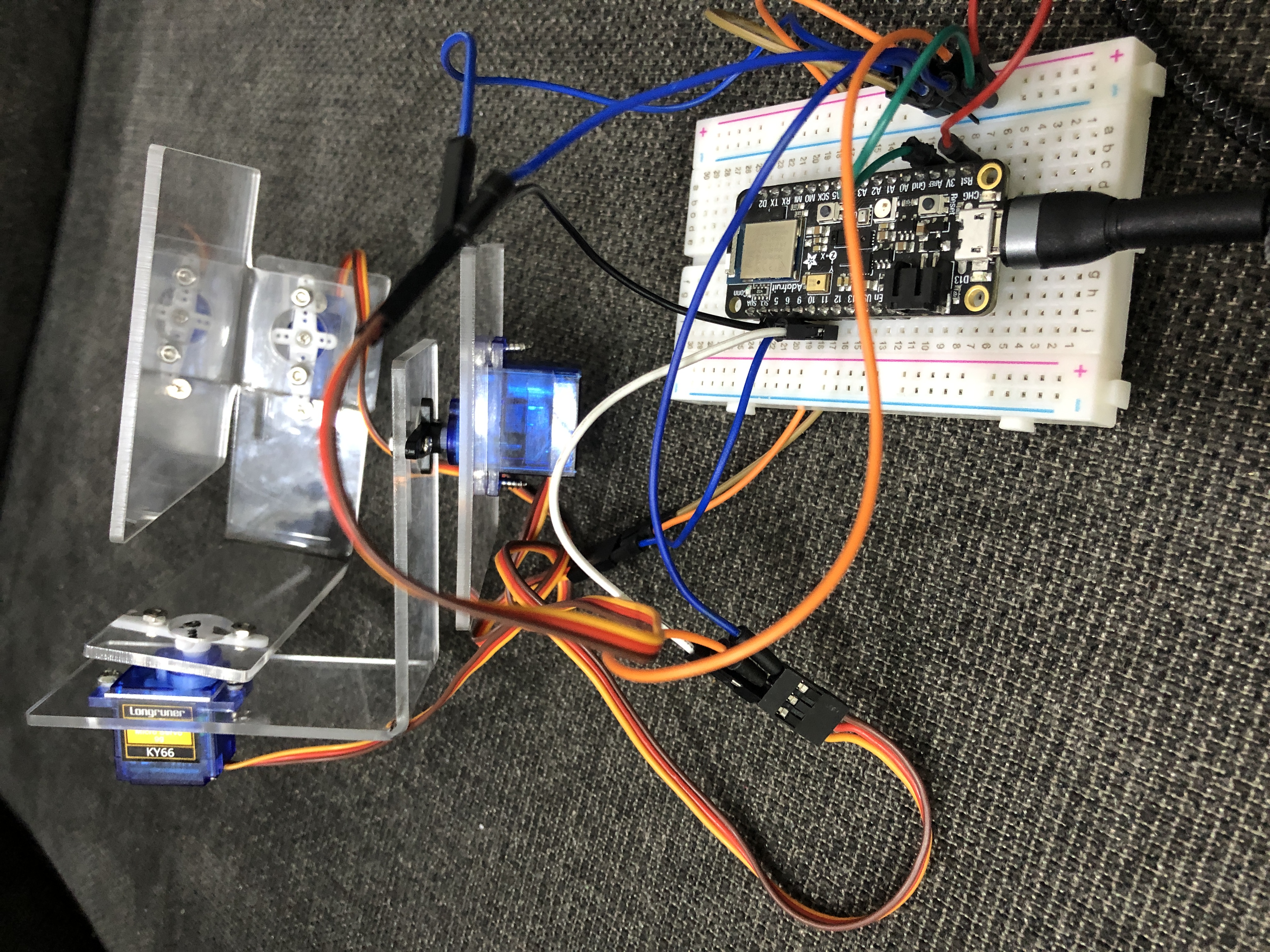
after its all assembled and the code is uploaded to the microcontroller. here is the results
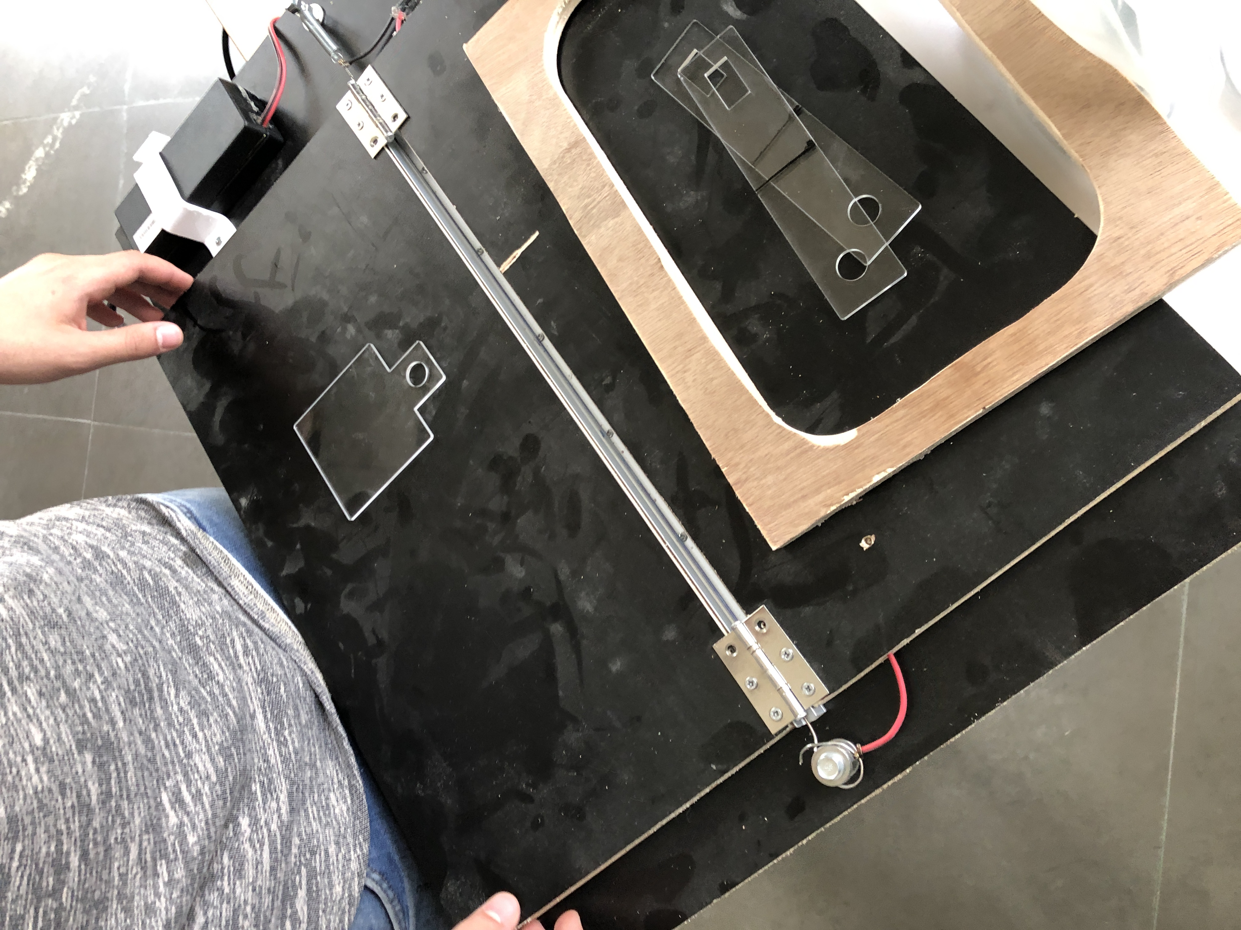
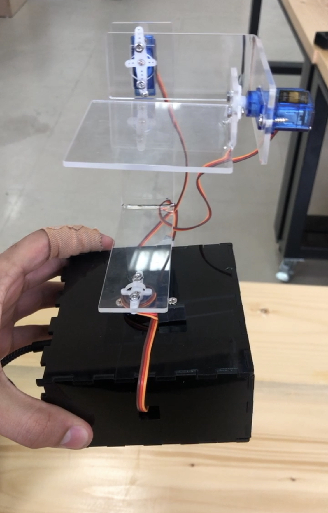
Final Product
here I put everything together, and got the project in the final form
Problems
- the range of motion is restricted by the range of the servos
- the motion of the servos was a bit aggressive and sharp
- the wires keep disconnecting even without any stress on them because the servo connector was a bit poor, this can be solved by soldering the wires.