7. Input & Output device
This week I worked on input and output devices connected to a MKR1010 microcontroller by recieving from the input and then sending to the output devices.
Signals
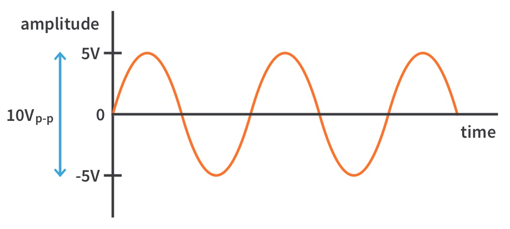
Analog signals are continuous in nature. Continuous signals exist in continuous time and amplitude, hence the name. To represent them graphically, consider time on the x-axis and the amplitude/value of the signal on the y-axis. For example, here is a sine wave of amplitude 10V peak to peak with a continuously changing voltage.
Analog Signals
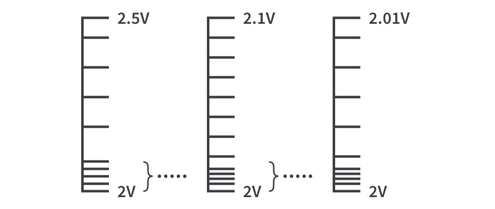
An analog signal comprises of a range of values which is usually limited by the maximum energy the power supply can provide. Using another example, the signal below can have a value of 2V, a value of 2.5V and any value in between. One could say an analog signal can have an infinite number of values since there are infinite numbers between 2 and 2.5.
Digital signals
Digital signals don’t take on these ranges of values, they are binary. Digital signals have two values: high and low which can be represented as 1 and 0. Our computers operate on the principle of billions of 1’s and 0’s, highs and lows, being processed billions of times per second!
Interfacing Devices
Interfacing can be defined as transferring data between microcontrollers and interfacing peripherals such as sensors, keypads, microprocessors, analog to digital converters or ADC, LCD displays, motors, external memories, even with other microcontrollers, some other interfacing peripheral devices and so on or input devices and output devices. These devices that are interfacing with 8051 microcontroller are used for performing special tasks or functions are called as interfacing devices.
Interfacing is a technique that has been developed and being used to solve many composite problems in circuit designing with appropriate features, reliability, availability, cost, power consumption, size, weight, and so on. To facilitate multiple features with simple circuits, microcontroller is interfaced with devices such as ADC, keypad, LCD display and so on. A signal is an entity that represents information. This could be electric current, voltage, electromagnetic waves that are used for wireless communication, sound, etc.
Analog to Digital Converter (ADC)
A to D converter is an electronic integrated circuit used for converting the analog signals into a digital or binary form. Generally, analog to digital converters takes an input voltage from 0 to 10V, -5V to +5V, etc. and thereby converts this analog input into digital output. Most of the environmental parameters such as temperature, sound, pressure, light, etc. are measurable in analog form only. If we consider a temperature monitoring system, then obtaining, examining and handling temperature data from the temperature sensors is unable with the digital measuring system. Therefore, this system requires an intermediate device for converting the temperature from analog to digital data, such that for communicating with the digital system containing microcontrollers and microprocessors.
Tracking Sensor
The line tracking module is the type of infrared sensor module, which consists of two infrared sensors such as an infrared transmitter and an infrared receiver. It has almost the same working principle and construction as well as with infrared obstacles avoidance sensor module, but the only difference is that it has low transmitting power. This line tacking module has the property to detect a black line in white color and white line in black color. It provides a more stable and accurate output. These are easy to use and are easily available in the market or online shop. These are mostly used in the robotic industry as well as in those things in which infrared technology plays an important role such as scanner and door opening switches etc.
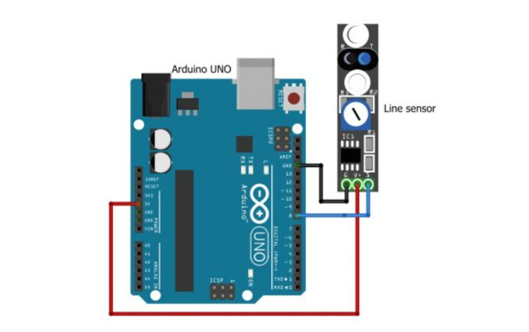
The connection is the same as you can see above.
| Tracking sensor | MKR1010 |
|---|---|
| G | GND |
| v+ | 5v |
| s | PIN 8 |
This is the code tha I have used from this website.
void setup() {
Serial.begin(9600);
pinMode(8,INPUT);

Serial.begin(9600);

}

void loop() {
bool value = digitalRead(8);


Serial.print(digitalRead(8));
delay(500);


}
I removed the buzzer and light part since there are no buzzer nor light I connected to this circuit.
Serial.print(digitalRead(8));
delay(500);
This line I wrote it so I can take the sensing result to the serial monitor and take values from it so the sensor will act as an input device that gives me value in the digital for and 1 means the sensor is not tracking anything and 0 means there is some object which in this case my ginger is detected.
Servo Motor
- Servo motor is an electrical device which can be used to rotate objects (like robotic arm) precisely.
- Servo motor consists of DC motor with error sensing negative feedback mechanism. This allows precise control over angular velocity and position of motor. In some cases, AC motors are used.
- It is a closed loop system where it uses negative feedback to control motion and final position of the shaft.
- It is not used for continuous rotation like conventional AC/DC motors.
- It has rotation angle that varies from 0° to 180°.
This is an output device which in my case I used it and connected it to the microcontroller so it will rotate the motor if the sensor tracked something near it.
here were we can find the code in Arduino IDE
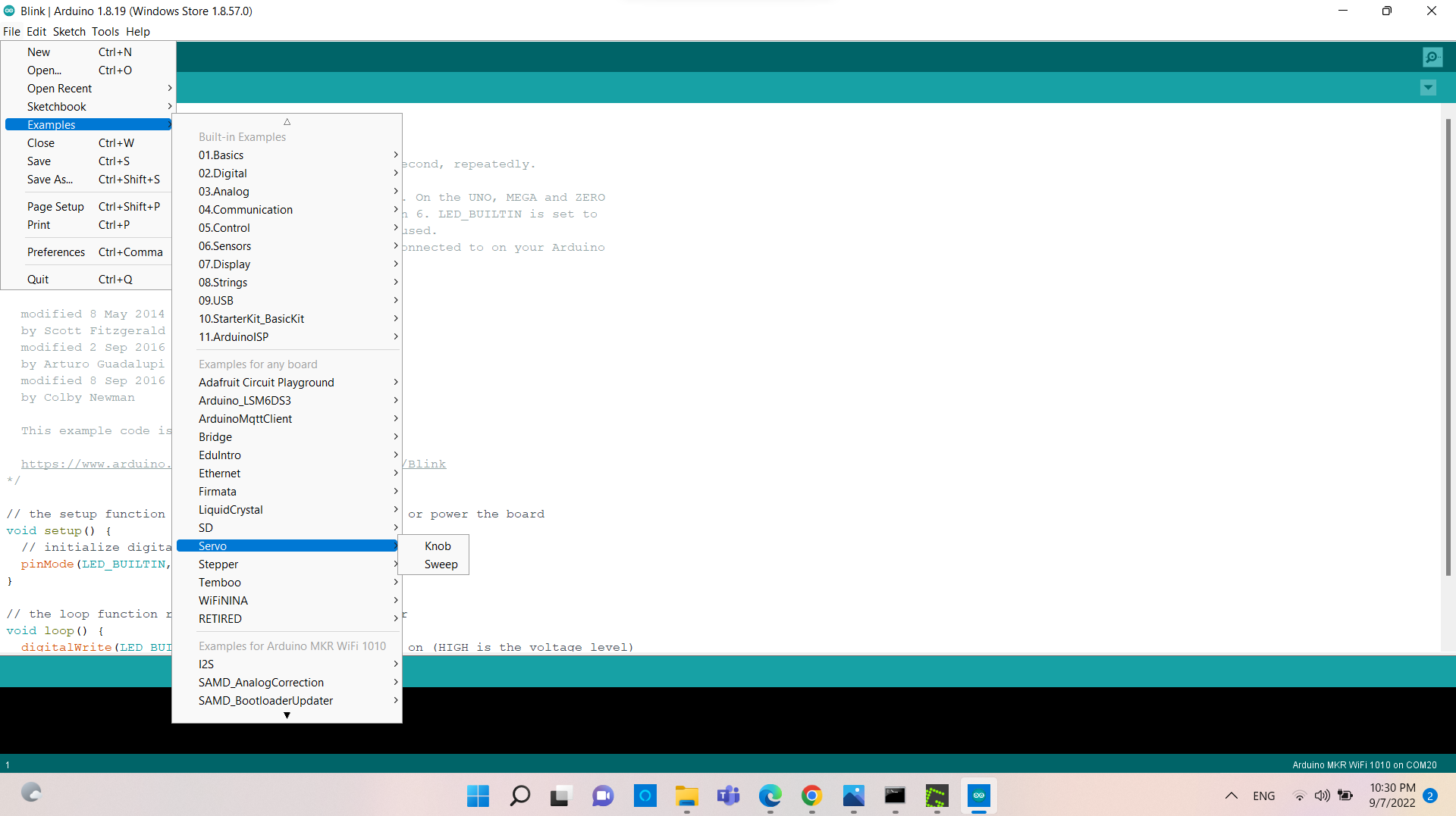
/* Sweep
 by BARRAGAN <http://barraganstudio.com>
 This example code is in the public domain.

 modified 8 Nov 2013
 by Scott Fitzgerald
 https://www.arduino.cc/en/Tutorial/LibraryExamples/Sweep
*/

#include <Servo.h>

Servo myservo;  // create servo object to control a servo
// twelve servo objects can be created on most boards

int pos = 0;    // variable to store the servo position

void setup() {
  myservo.attach(9);  // attaches the servo on pin 9 to the servo object
}

void loop() {
  for (pos = 0; pos <= 180; pos += 1) { // goes from 0 degrees to 180 degrees
    // in steps of 1 degree
    myservo.write(pos);              // tell servo to go to position in variable 'pos'
    delay(15);                       // waits 15 ms for the servo to reach the position
  }
  for (pos = 180; pos >= 0; pos -= 1) { // goes from 180 degrees to 0 degrees
    myservo.write(pos);              // tell servo to go to position in variable 'pos'
    delay(15);                       // waits 15 ms for the servo to reach the position
  }
}
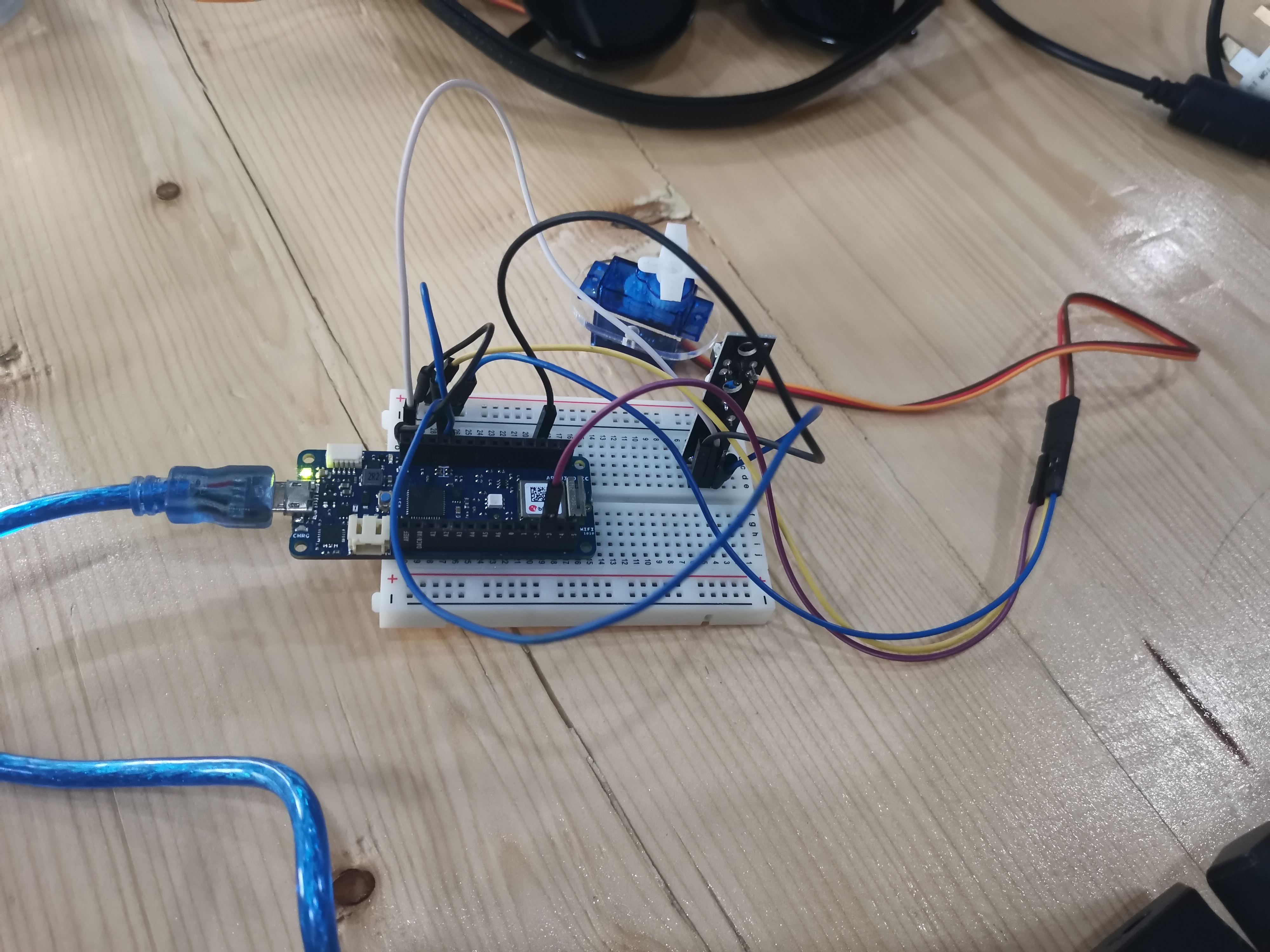
Tracking sensor and Servo motor
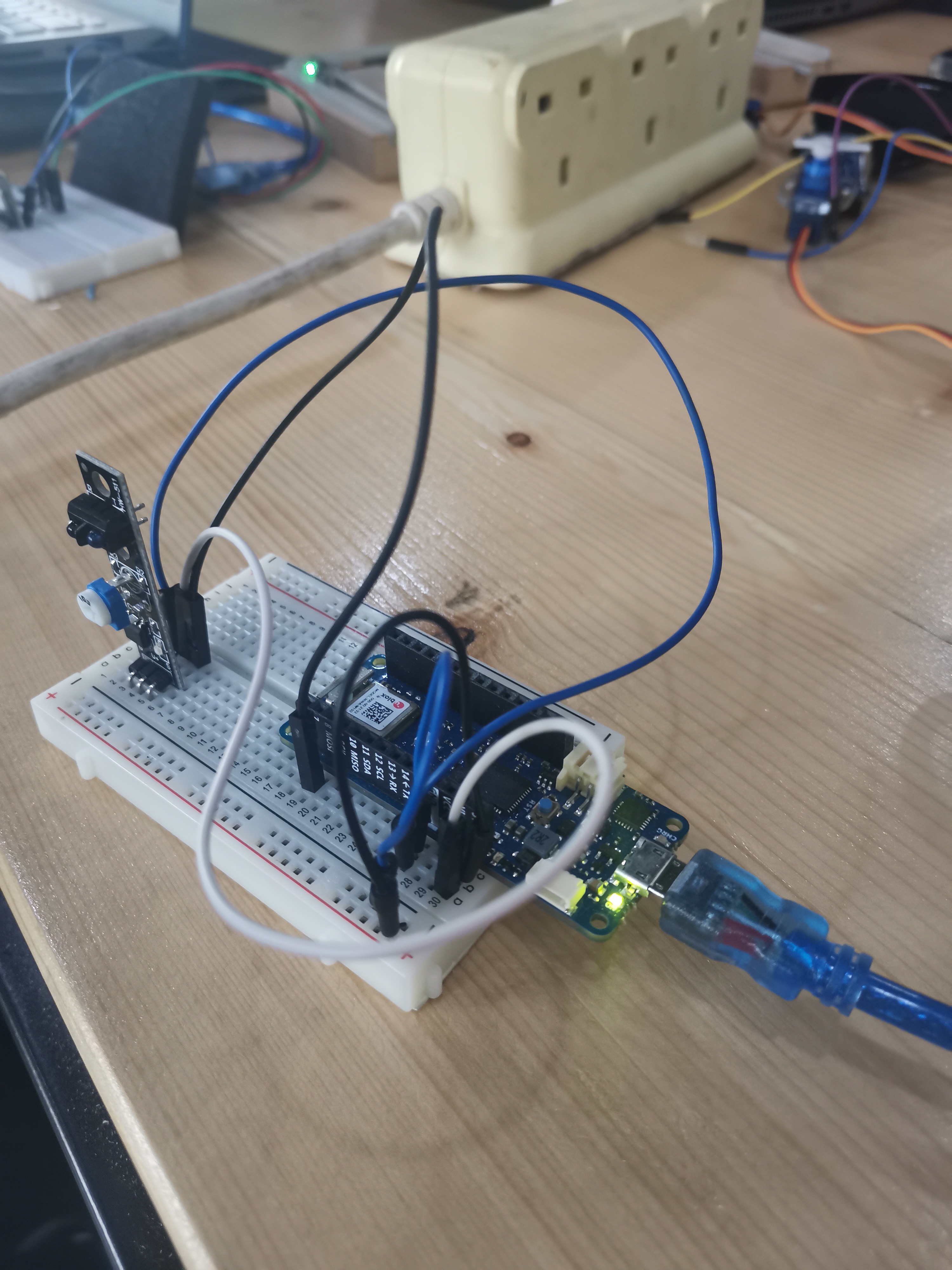
connecting the sensor to the servo motor so the sensor will act as an input and if it sense any motion the servo motor will act as an output and it will the shaft that is connected to the fan will move on 180 degree on both sides.
| Tracking sensor | MKR1010 |
|---|---|
| G | GND |
| v+ | 5v |
| s | PIN 8 |
| Servo motor | MKR1010 |
|---|---|
| Brown (darkest shade is always ground) | GND |
| Red (middle) | 5v |
| Yellow | PIN 3 |
here I connected the of tracking and you can find it above with the servo motor code so that if the tracking sensor worked it will rotate the motor. if the value==0 means if the sensor sense any tracking.
#include<Servo.h>

Servo Myservo;

int i;

void setup() {
Serial.begin(9600);
pinMode(8,INPUT);

Serial.begin(9600);
Myservo.attach(3);
}

void loop() {
bool value = digitalRead(8);
if(value == 0)
{

for(i=0;i<=180;i++){
Myservo.write(i);
delay(10);
}
  delay(1500);

  for(i=180;i>=0;i--){
Myservo.write(i);
delay(10);
}
  delay(1500);
}

Serial.print(digitalRead(8));
delay(500);

}
LED
KY-009
Pulse width modulation [PWM] can be used to regulate the brightness of an LED - in this process, the LED is switched on and off at specific time intervals, with the ratio of the switch-on and switch-off times corresponding to a relative brightness. Due to the inertia of human vision, human eyes interpret such on/off behavior as a change in brightness.
PWM
Digital signals have two positions: on or off, interpreted in shorthand as 1 or 0. Analog signals, on the other hand, can be on, off, half-way, two-thirds the way to on, and an infinite number of positions between 0 and 1 either approaching 1 or descending down to zero. The two are handled very differently in electronics, but very often must work together (that’s when we call it “mixed signal electronics.”) Sometimes we have to take an analog (real world) input signal (e.g., temperature) into a microcontroller (which only understands digital). Often engineers will translate that analog input into digital input for the microcontroller (MCU) by using an analog-to-digital converter.
PWM is a way to control analog devices with a digital output. Another way to put it is that you can output a modulating signal from a digital device such as an MCU to drive an analog device. It’s one of the primary means by which MCUs drive analog devices like variable-speed motors, dimmable lights, actuators, and speakers. PWM is not true analog output, however. PWM “fakes” an analog-like result by applying power in pulses, or short bursts of regulated voltage.
a PWM signal shown at several duty cycles and a high voltage level of 5 volts. The red line is the average voltage that the driven device
| KY-009 | MKR1010 |
|---|---|
| - | vcc |
| R | PIN 9 |
| B | PIN 11 |
| G | PIN 10 |
I used 3 resistors to protect the LED from high curren that can damage it by reducing the current that enter to the LED. The voltage given from the MKR1010 is 3.3v and voltage for the red, blue and green leds are 1.8V, 2.8V and 2.8V respectively while the forward current is limited to 20 mA. so by subtracting each voltage of the three colours from 3.3v then dividing all of them by the limit curren which is 20 mA we get 75 ohm, 25 ohm and 25 ohm respectively. But in my case I took higher resistors than the one i calculated to double protecet the LED.
// Pins
#define BLUE 11
#define GREEN 10
#define RED 9
#define delayTime 10 // fading time
int MAX_LUM = 255;
int redVal,greenVal,blueVal;
void setup()
{
pinMode(RED, OUTPUT);
pinMode(GREEN, OUTPUT);
pinMode(BLUE, OUTPUT);
digitalWrite(RED, HIGH);
digitalWrite(GREEN, LOW);
digitalWrite(BLUE, LOW);
}
void loop()
{
redVal = MAX_LUM; // choose a Val between 1 and 255 to change the color.
greenVal = 0;
blueVal = 0;
for(int i = 0; i < MAX_LUM; i += 1) // fades out red bring green full when i=255
{
redVal -= 1;
greenVal += 1;
lightRGB(redVal, greenVal, blueVal);
delay(delayTime);
}
redVal = 0;
greenVal = MAX_LUM;
blueVal = 0;
for(int i = 0; i < MAX_LUM; i += 1) // fades out green bring blue full when i=255
{
greenVal -= 1;
blueVal += 1;
lightRGB(redVal, greenVal, blueVal);
delay(delayTime);
}
redVal = 0;
greenVal = 0;
blueVal = MAX_LUM;
for(int i = 0; i < MAX_LUM; i += 1) // fades out blue bring red full when i=255
{
// The following code has been rearranged to match the other two similar sections
blueVal -= 1;
redVal += 1;
lightRGB(redVal, greenVal, blueVal);
delay(delayTime);
}
}
void lightRGB(int r, int g, int b){
analogWrite(RED, r);
analogWrite(GREEN, g);
analogWrite(BLUE, b);
}
Problem
In the servo motor task I had in the first place a motor that viberate but we I put the plastic fan on the shaft it does not move so I switched the servo motor to another one and it worked. and the other problem is that the servo motor does not specify which wire identification so we needed to search about it and we found that always the ground wire is represented by the darker colour and in the middle is always the wire we need to connect it with the power.