Input & Output Devices
This week I worked on different elements that is either output or input devices including how to program them & connections
Types of wires
-
Positive: Voltage common collector (vcc) or vin
-
Negative: Ground or GND
Different Aspects
-
Microcontroller: can be used as power source
-
Digital: alternating voltage between high & low
-
Analog: Can have many voltage due to the sinusoidal pattern. In other words you can control voltage amount using it
-
Currents: We have two types of currents AC & DC
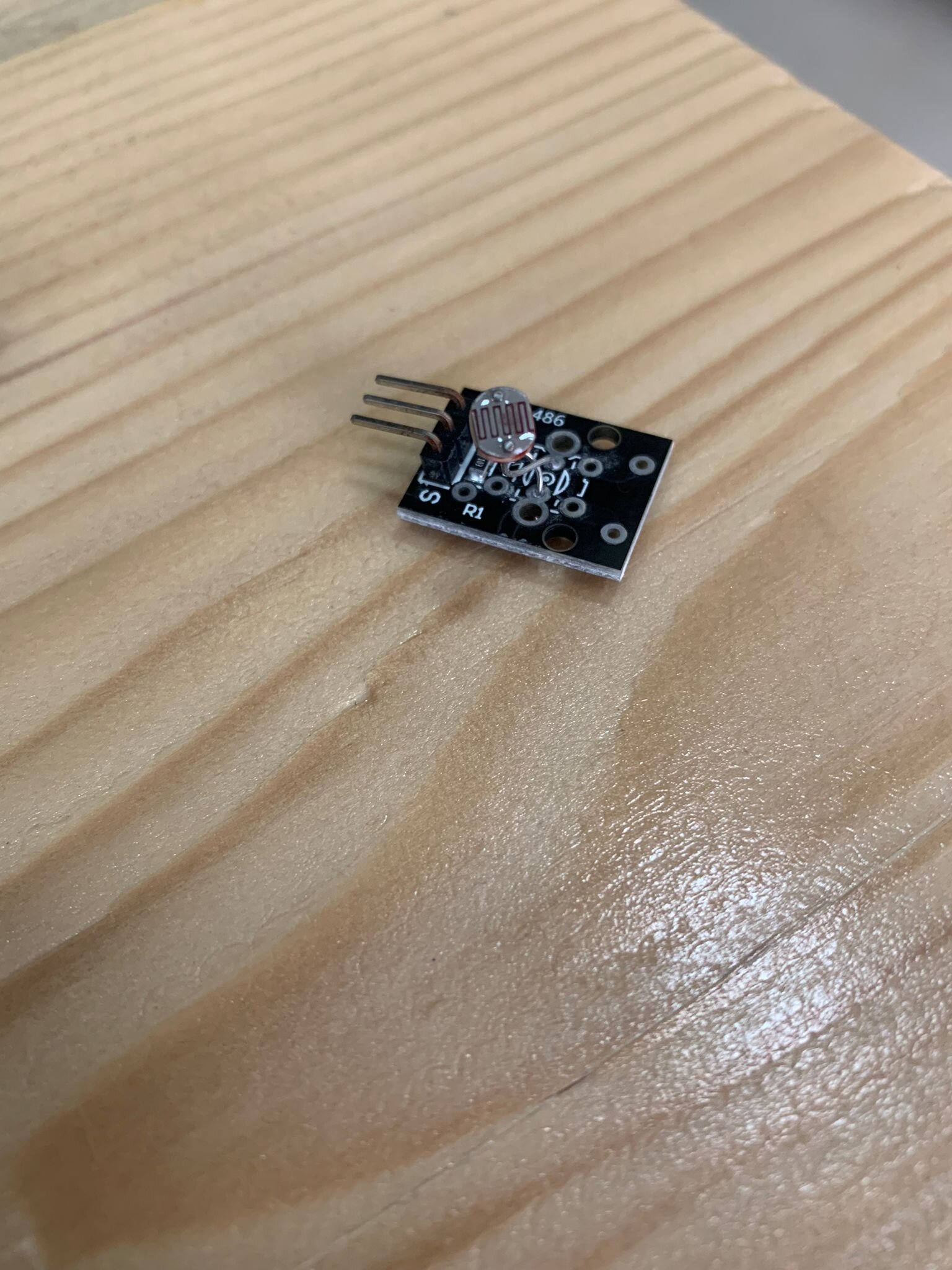
Input Sensors
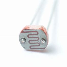
- Light Sensor It works on the photoresistor light sensitivity and resistance to the amount of light falling on it
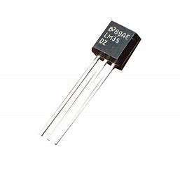
- Temperature Sensor Device used to measure temperature depending on its resistance & the received voltage
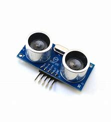
- Ultrasonic Sensor It is distance sensor it measures the distance by emitting high frequency sound waves and receiving the reflection back. The time it takes to go & rebound is calculated and converted to distance
Output Device Experiment
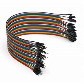
Jumper Wires
There are three types of jumpers
-
Male to Male
-
Male to Female
-
Female to Female
The difference between male & female is the end point of the wire male have pins that used to be plugged into things, whereas female ends is open and needs things to be plugged into. Another thing to mention is color do not mean anything
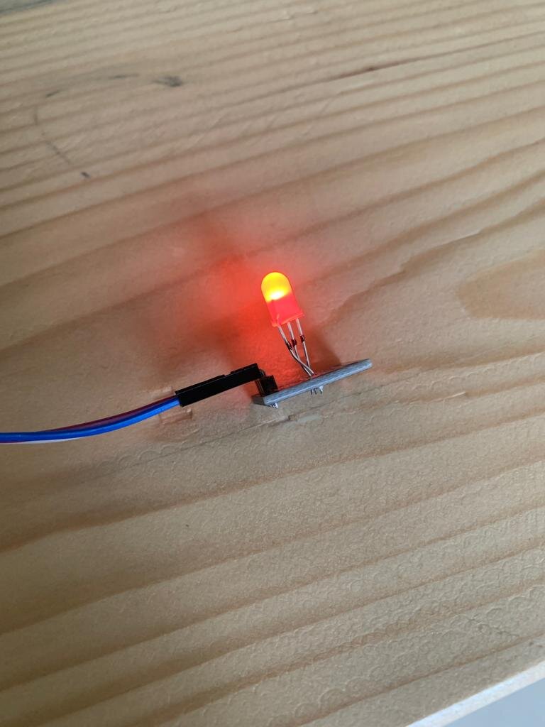
7 Color Flash
-
My first experiment was with RGB LED device that can show us colors- RED,BLUE & GREEN.
-
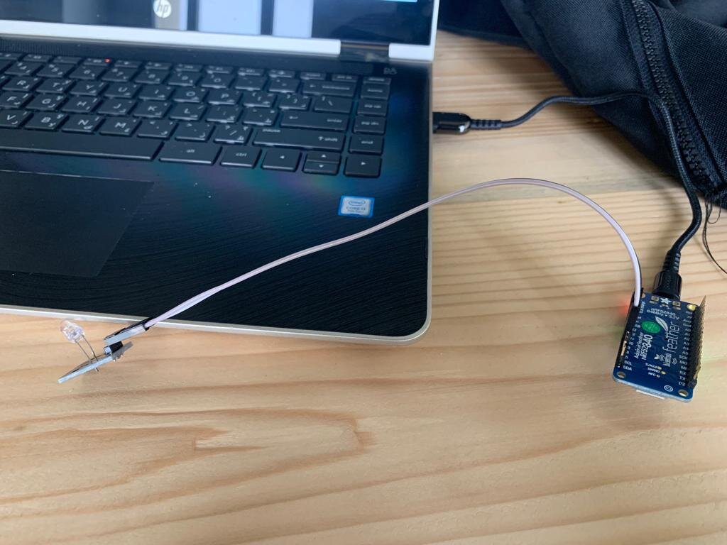
It has three pins so I used three female to female jumpers to connect it with my Microcontroller
- Then I connect it to the laptop and port it using Arduino IDE refer to embedding programming week
- I used Blink with little modification
int red = 10;
int green = 12;

// the setup function runs once when you press reset or power the board
void setup() {
  // initialize digital pin LED_BUILTIN as an output.
  pinMode(red, OUTPUT);
  pinMode(green, OUTPUT);


}

// the loop function runs over and over again forever
void loop() {
  digitalWrite(red, HIGH);   // turn the LED on (HIGH is the voltage level)
  delay(1000);                       // wait for a second
  digitalWrite(green, HIGH);    // turn the LED off by making the voltage LOW
  delay(1000);                       // wait for a second
}
- Then uploaded it to the microcontroller & here is the final results
RGB LED
I used for it 4 female to female jumpers connected red to pin 13, green to pin 6 & blue to pin=10. Then I applied the code and used the same method
int red_light_pin= 13;
int green_light_pin = 6;
int blue_light_pin = 10;
void setup() {
  pinMode(red_light_pin, OUTPUT);
  pinMode(green_light_pin, OUTPUT);
  pinMode(blue_light_pin, OUTPUT);
}
void loop() {
  RGB_color(255, 0, 0); // Red
  delay(1000);
  RGB_color(0, 255, 0); // Green
  delay(1000);
  RGB_color(0, 0, 255); // Blue
  delay(1000);
  RGB_color(255, 255, 125); // Raspberry
  delay(1000);
  RGB_color(0, 255, 255); // Cyan
  delay(1000);
  RGB_color(255, 0, 255); // Magenta
  delay(1000);
  RGB_color(255, 255, 0); // Yellow
  delay(1000);
  RGB_color(255, 255, 255); // White
  delay(1000);
}
void RGB_color(int red_light_value, int green_light_value, int blue_light_value)
 {
  analogWrite(red_light_pin, red_light_value);
  analogWrite(green_light_pin, green_light_value);
  analogWrite(blue_light_pin, blue_light_value);
}
I used the following site to check different colors
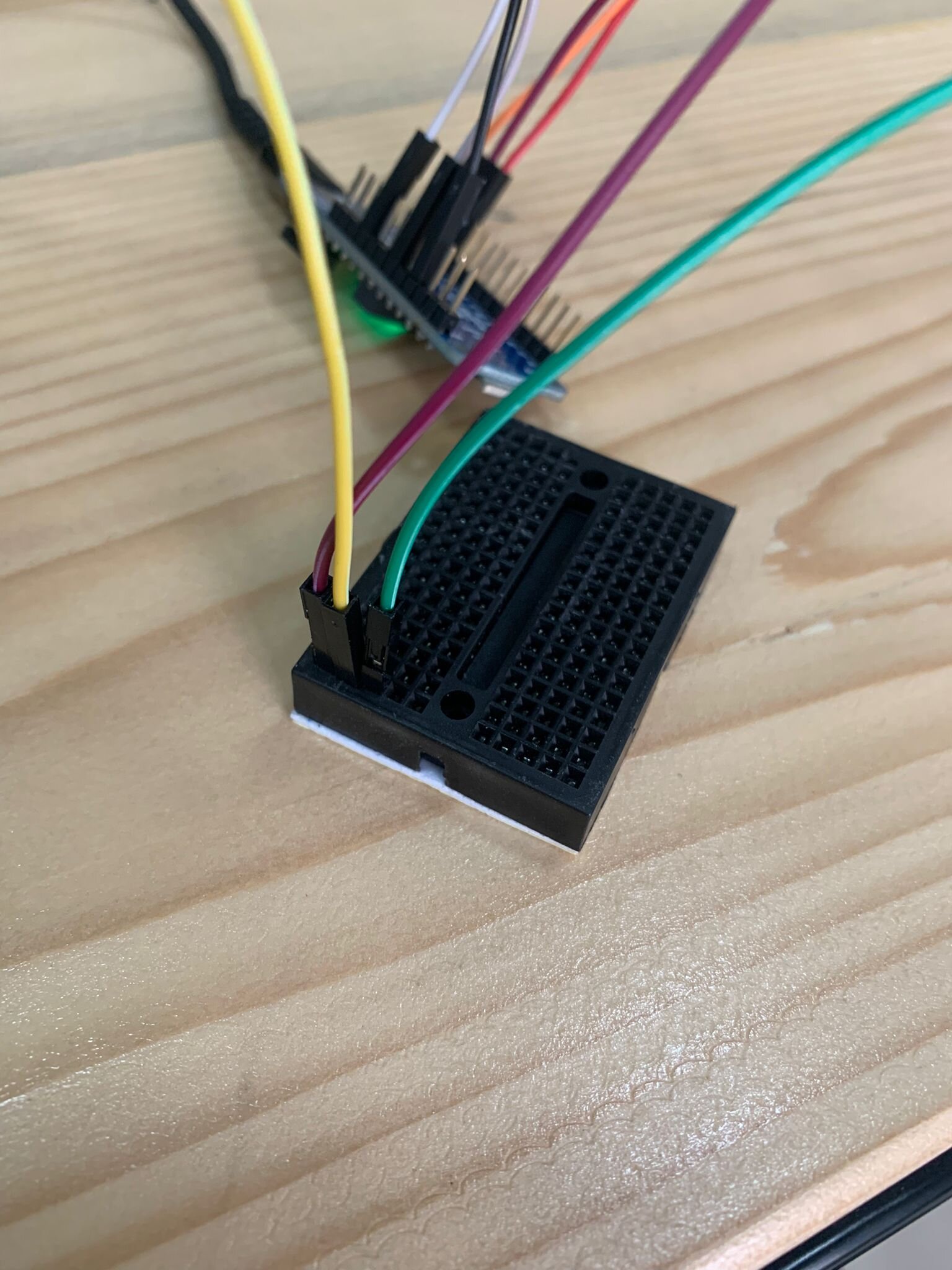
Input Experiment
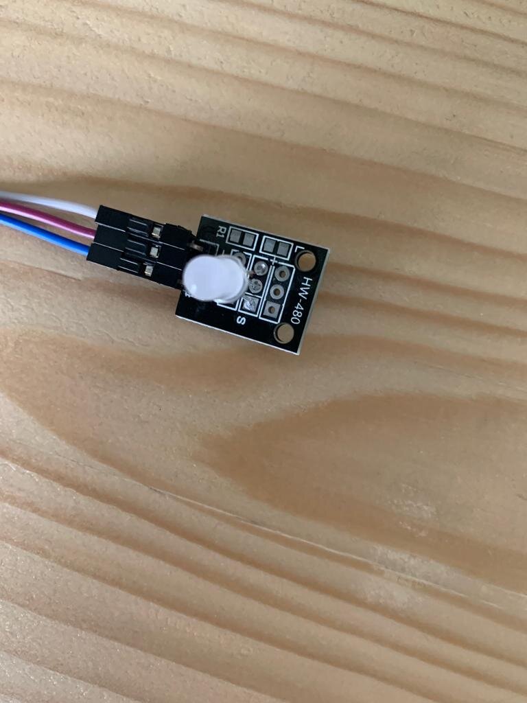
Light Sensor
In this section I tried to connect the light sensor to RGB LED in order to control it in this way
-
if there is light LED will turn off
-
if it is dark LED will work
To do so I used common ground to connect both LED & light sensor grounds
Then I used the following Code
int red_light_pin= 13;
int green_light_pin = 6;
int blue_light_pin = 10;
const int LIGHT_SENSOR_PIN = A0; // Arduino pin connected to light sensor's  pin
const int ANALOG_THRESHOLD = 500;
int analogValue;
void setup() {
  pinMode(red_light_pin, OUTPUT);
  pinMode(green_light_pin, OUTPUT);
  pinMode(blue_light_pin, OUTPUT);
}
void loop() {
  analogValue = analogRead(LIGHT_SENSOR_PIN); // read the input on analog pin

 if(analogValue > ANALOG_THRESHOLD)
 {
     RGB_color(255, 0, 0); // Red
     delay(1000);
     RGB_color(0, 255, 0); // Green
     delay(1000);
     RGB_color(0, 0, 255); // Blue
     delay(1000);
     RGB_color(255, 255, 125); // Raspberry
     delay(1000);
     RGB_color(0, 255, 255); // Cyan
     delay(1000);
     RGB_color(255, 0, 255); // Magenta
     delay(1000);
     RGB_color(255, 255, 0); // Yellow
     delay(1000);
     RGB_color(255, 255, 255); // White
     delay(1000);
 }
 else
    RGB_color(0, 0, 0);

}
void RGB_color(int red_light_value, int green_light_value, int blue_light_value)
 {
  analogWrite(red_light_pin, red_light_value);
  analogWrite(green_light_pin, green_light_value);
  analogWrite(blue_light_pin, blue_light_value);
}
Hero Video
Problems
-
Having multiple ground connections-solved by putting common grounds
-
Connecting to different pin- solved by either changing the pin position or code pin no
-
Multiple Code Errors-solved by editing the code to correct mistakes