Embedded Programming
This week I worked on embedded programming with some researches about microcontrollers and languages to be used for coding+ some tools to program with.
Group Assignment
Our group task is the first task to search about microcontrollers and choose same types to compare between them we summarized our research in this table
| Adafruit | Arduino | Bluefruit sense | FRDM-KL467 | |
|---|---|---|---|---|
| Power (voltages) | Power Input voltage 5V Output voltage 3.3V | Typically works on 5V | Input voltage 5V Output voltage 3.3V | Input voltage 3.6 V Output voltage 3.3V |
| Pins | 6 input – read switches/ turn LEDS and talk to sensors | 14 inputs/outputs | Multiple Pins: power pins/ logic pins and others like RST-ARef | 36 pins including Vcc/GND |
| Sensors | Force sensor/Flow sensor | Light sensors/Sound sensor/Air pressure sensor/Temperature sensor | Temperature sensor/Motion sensor/ Sound sensor | Capacitive touch slider/ MMA8451Q accelerometer |
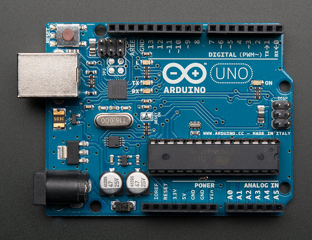
- Arduino
- Adafruit
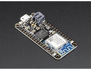
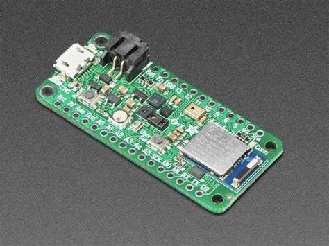
- Bluefruit
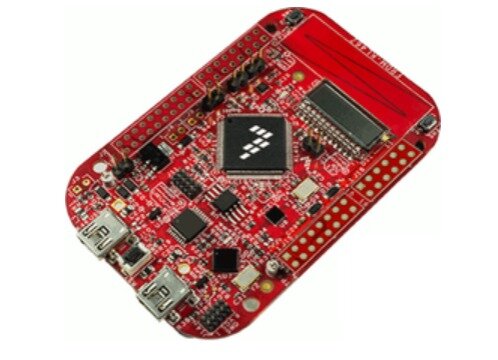
- FRDM-KL467
Research References
To find specific information about any controller you need to check its datasheet it will dive you details about each one also you can use the following links as starting point for your research
Group 2 assignment
Follow the below link to find info about programming languages
Arduino IDE
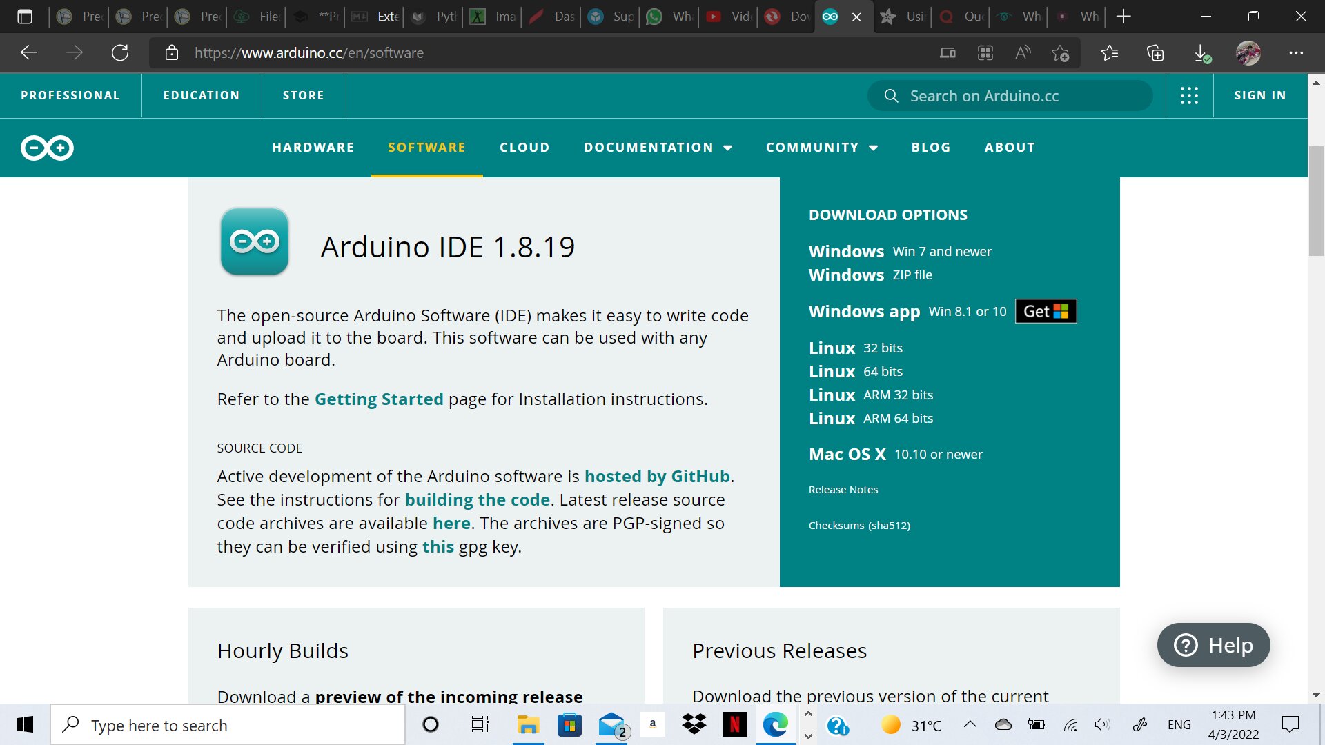
We will use this software to program and code our microcontroller. First you need to download the software from the following link
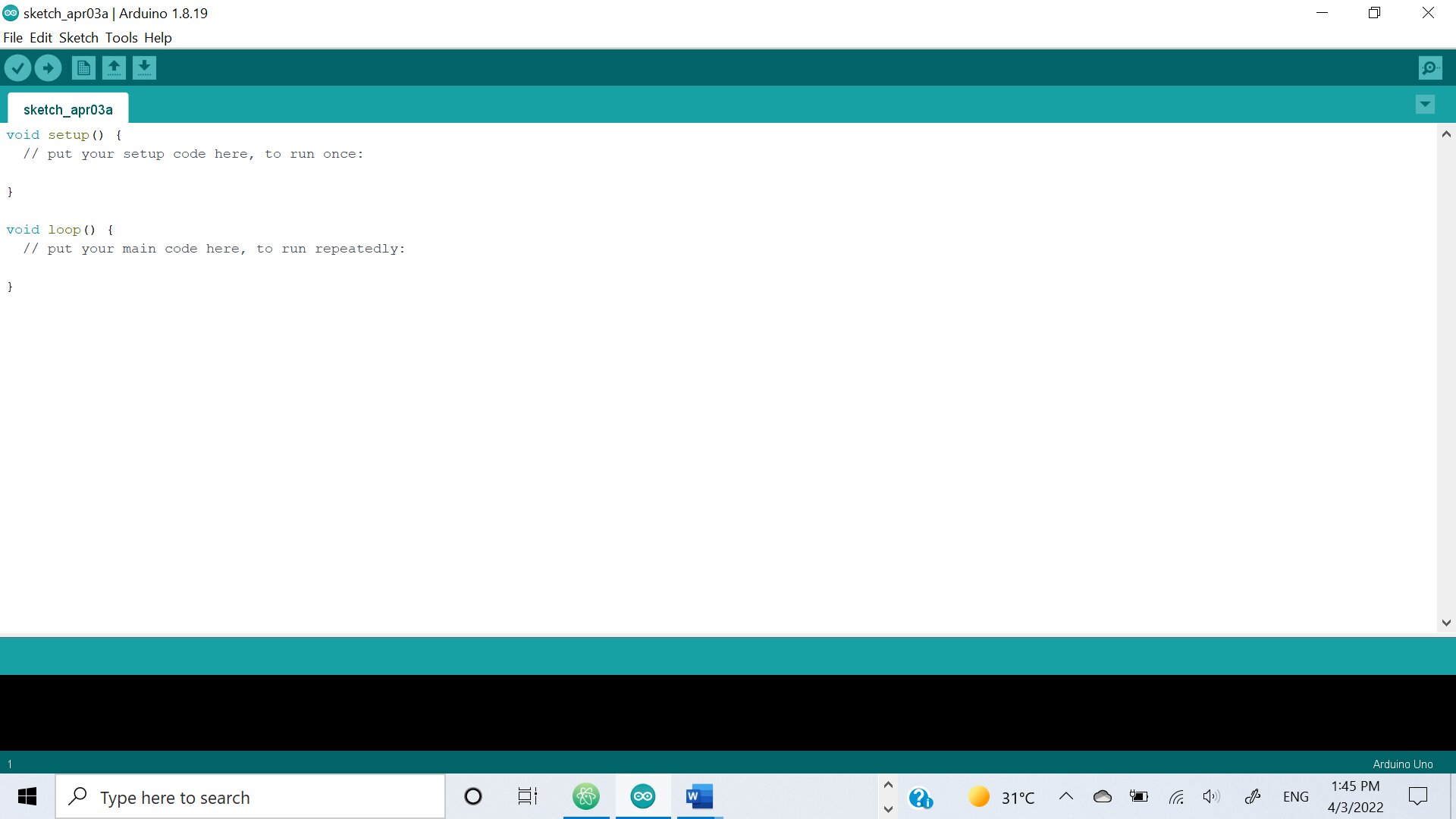
After its fully downloaded install the setup and run it
Setup your microcontroller
Mine was Adafruit nRF52840
- Datasheet
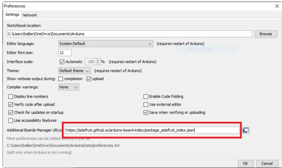
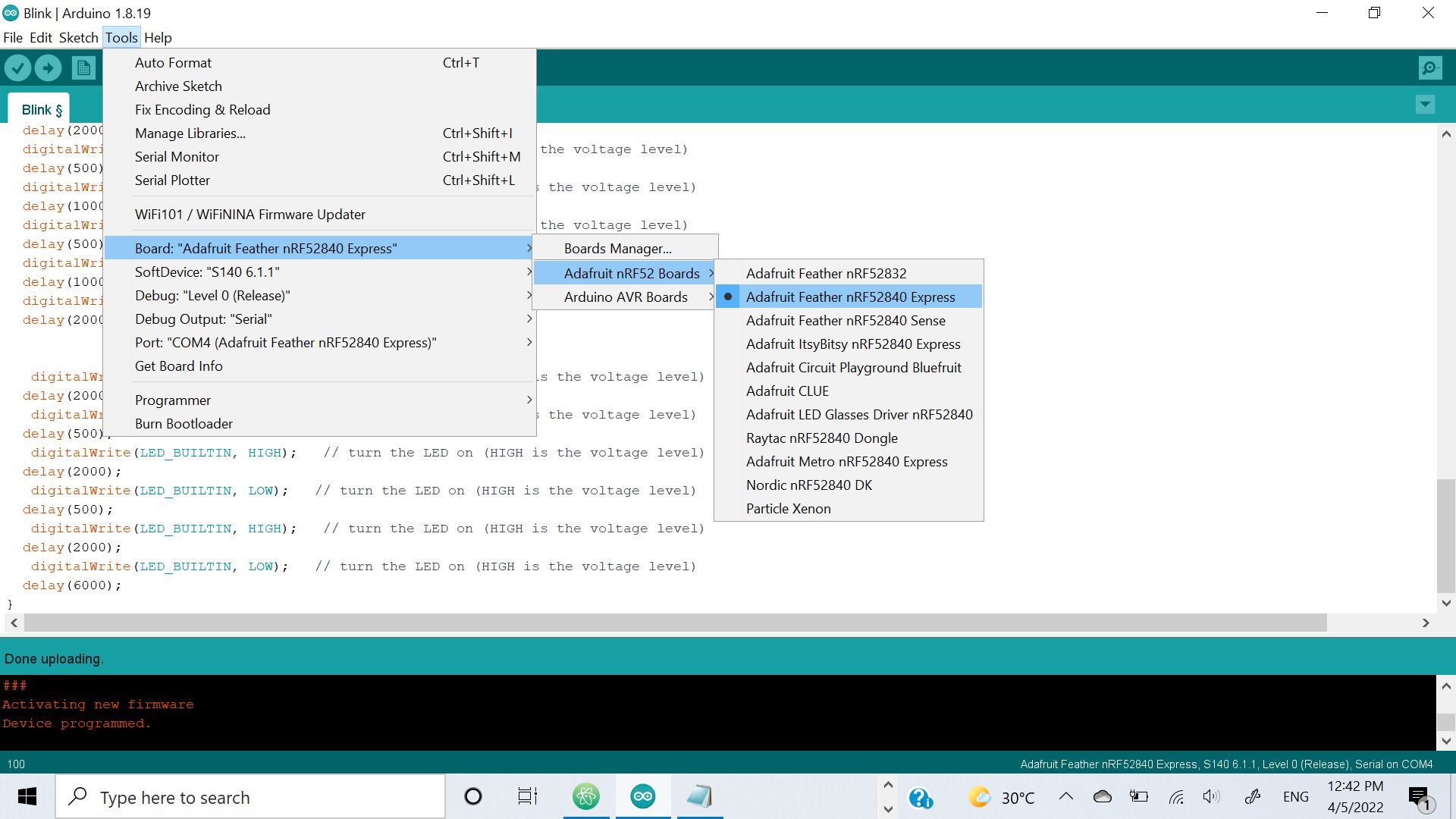
which is not available already on Arduino IDE so we needed to copy URL of the library from adafruit website you will find it in the following link
After that follow the steps listed in the same site above - File/Preferences/paste the URL there
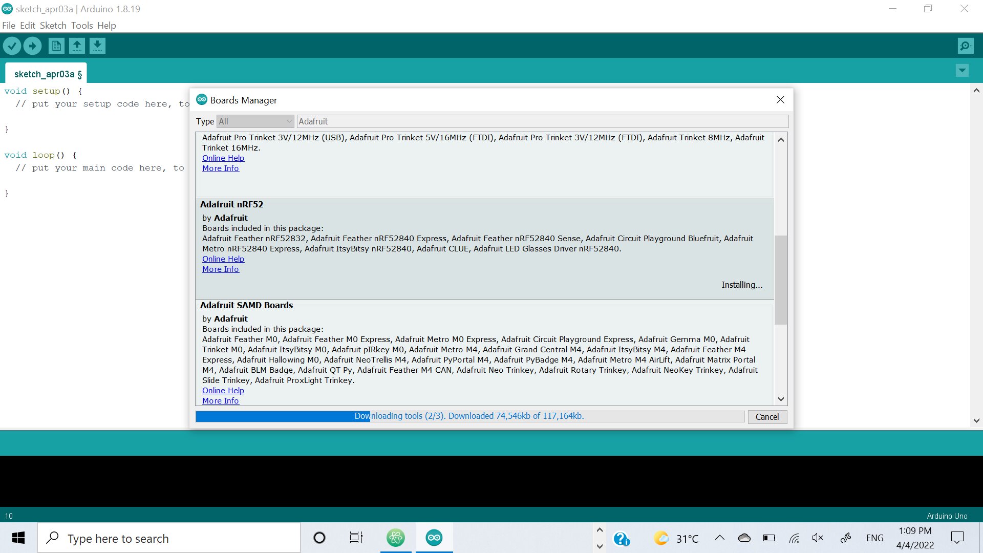
- Tools/Board/Board manager find adafruit nRF52 and install it
- Select the installed one from Tools/Board/Adafruit nRF52840 express
-
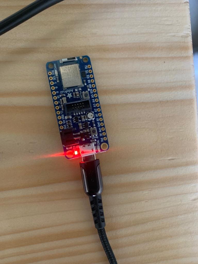
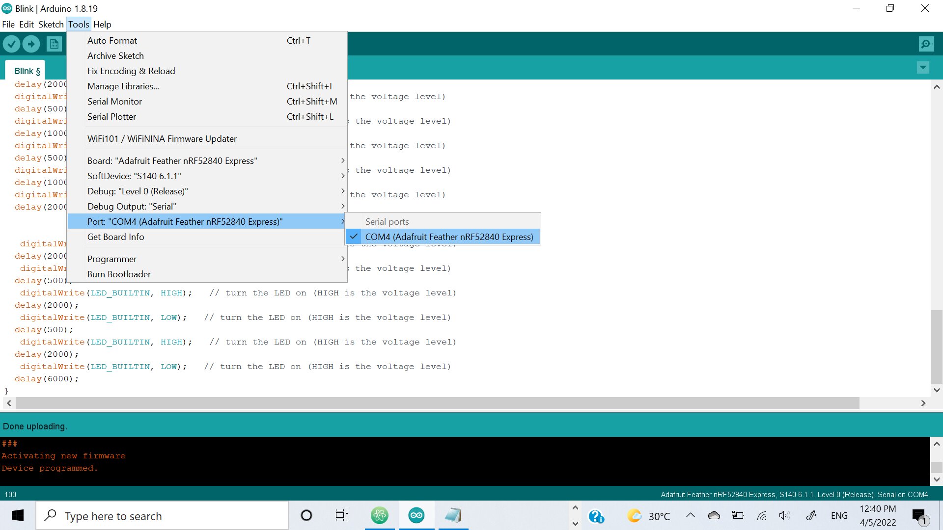
Connect the microcontroller with USB and insert it to your laptop
-
Tools/ Port and choose your microcontrollers
-
Click twice on it until green light is showing
And it is ready to be programmed :]
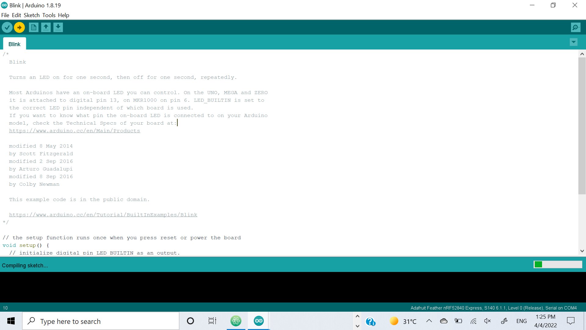
Blink
Simple programming code to make your microcontroller blink with the LED inserted on the board
simple follow this:
File - Example - Simple - Blink
You can control the time light is off and time it is on using the bottom loop of the code. In the same time you can repeat the code to give different timings each time. we explored many outcomes using blink
Blink simple code
 // the setup function runs once when you press reset or power the board
 void setup() {
   // initialize digital pin LED_BUILTIN as an output.
   pinMode(LED_BUILTIN, OUTPUT);
 }

 // the loop function runs over and over again forever
 void loop() {
   digitalWrite(LED_BUILTIN, HIGH);   // turn the LED on (HIGH is the voltage level)
   delay(1000);                       // wait for a second
   digitalWrite(LED_BUILTIN, LOW);    // turn the LED off by making the voltage LOW
   delay(1000);                       // wait for a second
 }
Morse Code
Morse code is a unique way to communicate were it language represented by combinations of long and short light or sound signals. It also can be written with dots, spaces and dashes you can use the following link to do so
We will apply this on our microcontroller to blink a word I chose the following word “Hello”
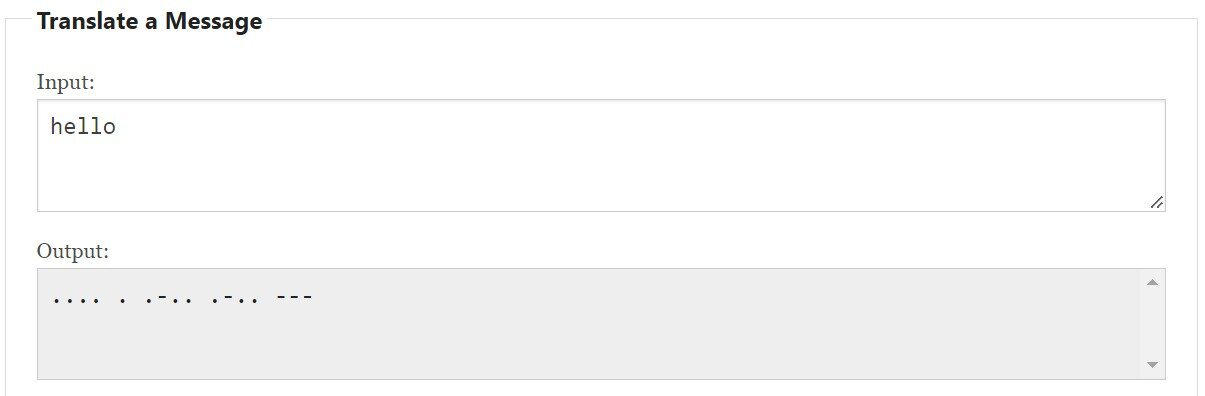
We will use the following rule to generate our code
(.) = 1sec on
(-) = 2sec on
( ) = 0.5sec off small space in same letter
( )= 2sec off space between two letters
- results of hello word
Blink

 Turns an LED on for one second, then off for one second, repeatedly.

 Most Arduinos have an on-board LED you can control. On the UNO, MEGA and ZERO
 it is attached to digital pin 13, on MKR1000 on pin 6. LED_BUILTIN is set to
 the correct LED pin independent of which board is used.
 If you want to know what pin the on-board LED is connected to on your Arduino
 model, check the Technical Specs of your board at:
 https://www.arduino.cc/en/Main/Products

 modified 8 May 2014
 by Scott Fitzgerald
 modified 2 Sep 2016
 by Arturo Guadalupi
 modified 8 Sep 2016
 by Colby Newman

 This example code is in the public domain.

 https://www.arduino.cc/en/Tutorial/BuiltInExamples/Blink
*/

// the setup function runs once when you press reset or power the board
void setup() {
 // initialize digital pin LED_BUILTIN as an output.
 pinMode(LED_BUILTIN, OUTPUT);
}

// the loop function runs over and over again forever
void loop() {
 digitalWrite(LED_BUILTIN, HIGH);   // turn the LED on (HIGH is the voltage level)
 delay(1000);                       // wait for a second
 digitalWrite(LED_BUILTIN, LOW);    // turn the LED off by making the voltage LOW
 delay(500);                       // wait for a second
 digitalWrite(LED_BUILTIN, HIGH);   // turn the LED on (HIGH is the voltage level)
 delay(1000);
 digitalWrite(LED_BUILTIN, LOW);    // turn the LED off by making the voltage LOW
 delay(500);
 digitalWrite(LED_BUILTIN, HIGH);   // turn the LED on (HIGH is the voltage level)
 delay(1000);
 digitalWrite(LED_BUILTIN, LOW);   // turn the LED on (HIGH is the voltage level)
 delay(500);
 digitalWrite(LED_BUILTIN, HIGH);   // turn the LED on (HIGH is the voltage level)
 delay(1000);
 digitalWrite(LED_BUILTIN, LOW);   // turn the LED on (HIGH is the voltage level)
 delay(2000);

 digitalWrite(LED_BUILTIN, HIGH);   // turn the LED on (HIGH is the voltage level)
 delay(1000);
 digitalWrite(LED_BUILTIN, LOW);   // turn the LED on (HIGH is the voltage level)
 delay(2000);

 digitalWrite(LED_BUILTIN, HIGH);   // turn the LED on (HIGH is the voltage level)
 delay(1000);
 digitalWrite(LED_BUILTIN, LOW);   // turn the LED on (HIGH is the voltage level)
 delay(500);
 digitalWrite(LED_BUILTIN, HIGH);   // turn the LED on (HIGH is the voltage level)
 delay(2000);
 digitalWrite(LED_BUILTIN, LOW);   // turn the LED on (HIGH is the voltage level)
 delay(500);
 digitalWrite(LED_BUILTIN, HIGH);   // turn the LED on (HIGH is the voltage level)
 delay(1000);
 digitalWrite(LED_BUILTIN, LOW);   // turn the LED on (HIGH is the voltage level)
 delay(500);
 digitalWrite(LED_BUILTIN, HIGH);   // turn the LED on (HIGH is the voltage level)
 delay(1000);
 digitalWrite(LED_BUILTIN, LOW);   // turn the LED on (HIGH is the voltage level)
 delay(2000);

   digitalWrite(LED_BUILTIN, HIGH);   // turn the LED on (HIGH is the voltage level)
 delay(1000);
 digitalWrite(LED_BUILTIN, LOW);   // turn the LED on (HIGH is the voltage level)
 delay(500);
 digitalWrite(LED_BUILTIN, HIGH);   // turn the LED on (HIGH is the voltage level)
 delay(2000);
 digitalWrite(LED_BUILTIN, LOW);   // turn the LED on (HIGH is the voltage level)
 delay(500);
 digitalWrite(LED_BUILTIN, HIGH);   // turn the LED on (HIGH is the voltage level)
 delay(1000);
 digitalWrite(LED_BUILTIN, LOW);   // turn the LED on (HIGH is the voltage level)
 delay(500);
 digitalWrite(LED_BUILTIN, HIGH);   // turn the LED on (HIGH is the voltage level)
 delay(1000);
 digitalWrite(LED_BUILTIN, LOW);   // turn the LED on (HIGH is the voltage level)
 delay(2000);


  digitalWrite(LED_BUILTIN, HIGH);   // turn the LED on (HIGH is the voltage level)
 delay(2000);
  digitalWrite(LED_BUILTIN, LOW);   // turn the LED on (HIGH is the voltage level)
 delay(500);
  digitalWrite(LED_BUILTIN, HIGH);   // turn the LED on (HIGH is the voltage level)
 delay(2000);
  digitalWrite(LED_BUILTIN, LOW);   // turn the LED on (HIGH is the voltage level)
 delay(500);
  digitalWrite(LED_BUILTIN, HIGH);   // turn the LED on (HIGH is the voltage level)
 delay(2000);
  digitalWrite(LED_BUILTIN, LOW);   // turn the LED on (HIGH is the voltage level)
 delay(500);
}
after finishing the code make sure green light is showing if not click twice on the button also make sure port is selecting your microcontroller. if everything is fine click on upload and you will find the following results
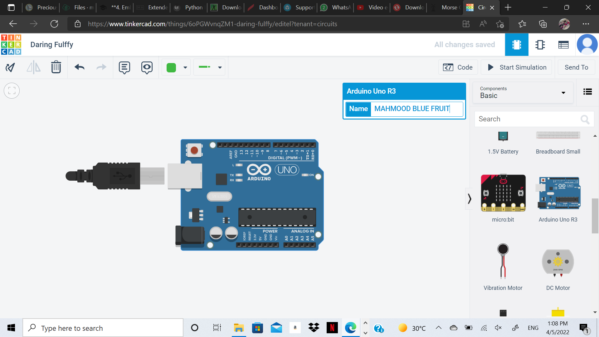
TinkerCad
Tinkercad also can be used to program like arduino IDE you need to choose electronics then the type of microelcontroller. if you are using adafruit you will not find it so use arduino because same coding is used
This site can make the code on the shape of blocks you can discover many function through it like repeat. I used it to make the same hello code
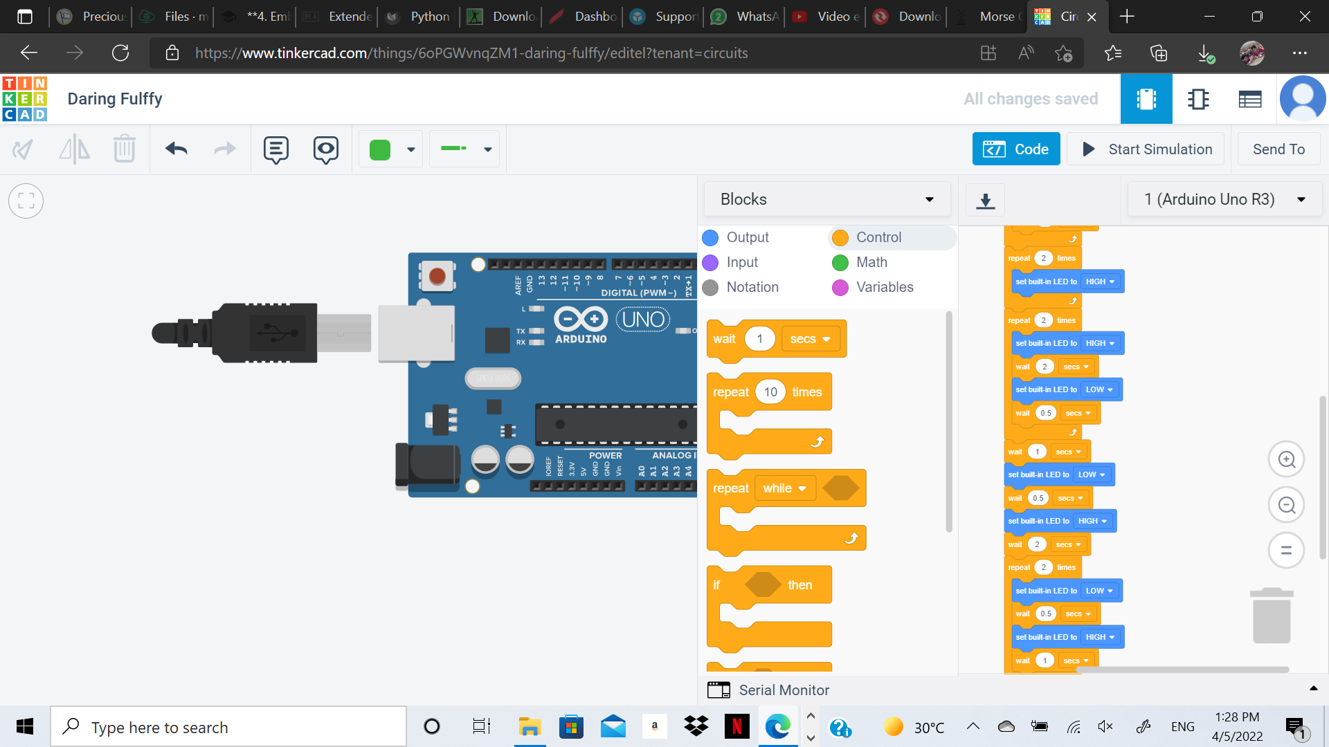
because I used repeat function the code is optimized with for inside the loop
// C++ code
//
int counter;

int counter2;

int counter3;

int counter4;

int counter5;

void setup()
{
  pinMode(LED_BUILTIN, OUTPUT);
}

void loop()
{
  for (counter = 0; counter < 3; ++counter) {
    digitalWrite(LED_BUILTIN, HIGH);
    delay(1000); // Wait for 1000 millisecond(s)
    digitalWrite(LED_BUILTIN, LOW);
    delay(500); // Wait for 500 millisecond(s)
  }
  for (counter2 = 0; counter2 < 2; ++counter2) {
    digitalWrite(LED_BUILTIN, HIGH);
    delay(1000); // Wait for 1000 millisecond(s)
    digitalWrite(LED_BUILTIN, LOW);
    delay(2000); // Wait for 2000 millisecond(s)
  }
  for (counter3 = 0; counter3 < 2; ++counter3) {
    digitalWrite(LED_BUILTIN, HIGH);
  }
  for (counter4 = 0; counter4 < 2; ++counter4) {
    digitalWrite(LED_BUILTIN, HIGH);
    delay(2000); // Wait for 2000 millisecond(s)
    digitalWrite(LED_BUILTIN, LOW);
    delay(500); // Wait for 500 millisecond(s)
  }
  delay(1000); // Wait for 1000 millisecond(s)
  digitalWrite(LED_BUILTIN, LOW);
  delay(500); // Wait for 500 millisecond(s)
  digitalWrite(LED_BUILTIN, HIGH);
  delay(2000); // Wait for 2000 millisecond(s)
  for (counter5 = 0; counter5 < 2; ++counter5) {
    digitalWrite(LED_BUILTIN, LOW);
    delay(500); // Wait for 500 millisecond(s)
    digitalWrite(LED_BUILTIN, HIGH);
    delay(1000); // Wait for 1000 millisecond(s)
  }
  digitalWrite(LED_BUILTIN, HIGH);
  delay(2000); // Wait for 2000 millisecond(s)
}
Tinkercad also allows simulation to any object external like LED to be connected to the Arduino through pin no 13
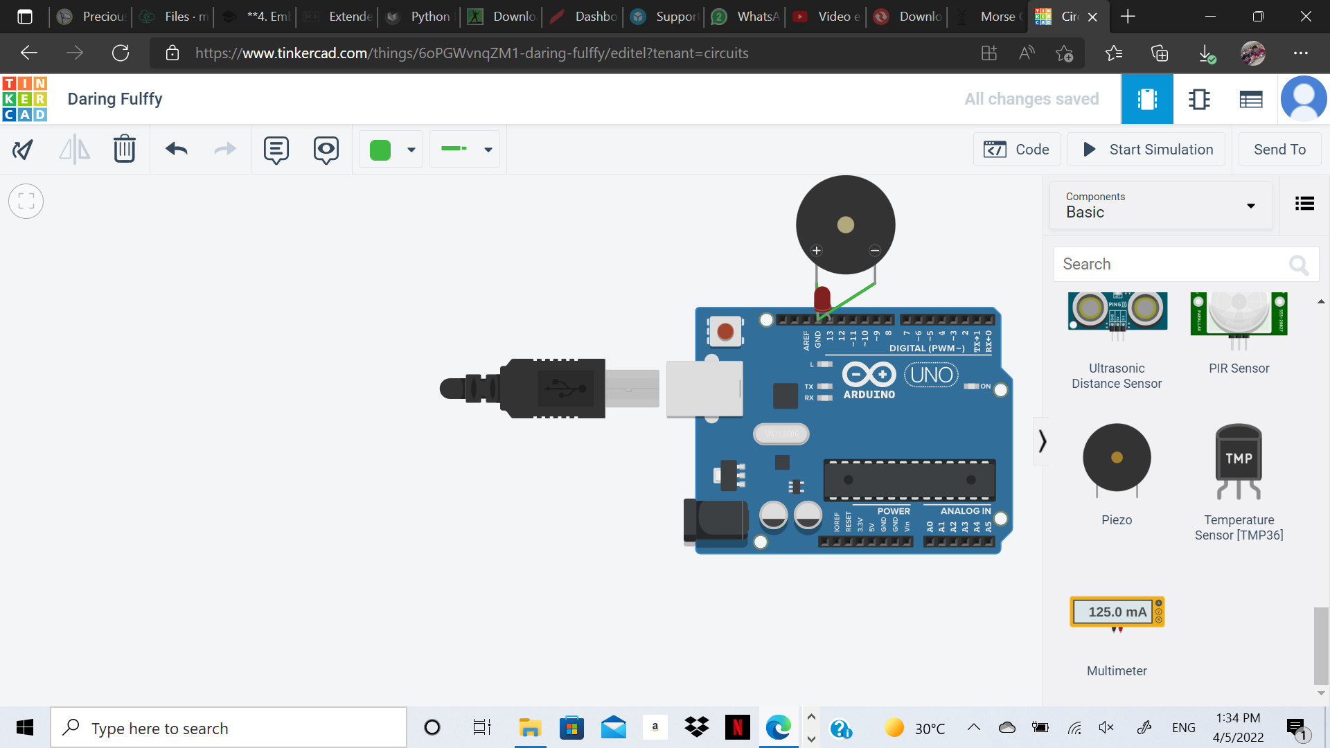
I also attached piezo or buzzer to the Arduino in order to generate music I used a code for the music I wanted
/* Play "He's A Pirate" / "Pirates of the Caribbean" Theme Song
 * By Xitang Zhao 2016.06.27
 *
 * INSTRUCTION: Hook up Pin 10 to the positive side of a buzzer or a microphone, hook up
 * any resistor to the negative side of a buzzer (to limit current & volume & to protect the pin),
 * and then connect the other end of the resistor to ground pin. Upload the sketch and enjoy!
 * Last updated: 2021.03.25
 * ---------------------
 * Credits:
 *
 * Music notes of the song obtained from Easy Music (Great website)
 * Link: http://easymusic.altervista.org/recorder-hes-a-pirate-pirates-of-caribbean-sheet-music-guitar-chords/
 *
 * Musicnotes's "How to Read Sheet Music" Guide
 * Link: http://www.musicnotes.com/blog/2014/04/11/how-to-read-sheet-music/
 *
 * Code inspired by Chapter 5 of Jeremy Blum's book "Exploring Arduino"
 * Link: http://www.exploringarduino.com/content/ch5/
 *
 * Music notes' frequencies obtained from arduino website and Tone Library
 * Link: https://www.arduino.cc/en/Tutorial/toneMelody
 * Link: https://github.com/bhagman/Tone
 *
 */

// Define pin 10 for buzzer, you can use any other digital pins (Pin 0-13)
const int buzzer = 10;

// Change to 0.5 for a slower version of the song, 1.25 for a faster version
const float songSpeed = 1.0;

// Defining frequency of each music note
#define NOTE_C4 262
#define NOTE_D4 294
#define NOTE_E4 330
#define NOTE_F4 349
#define NOTE_G4 392
#define NOTE_A4 440
#define NOTE_B4 494
#define NOTE_C5 523
#define NOTE_D5 587
#define NOTE_E5 659
#define NOTE_F5 698
#define NOTE_G5 784
#define NOTE_A5 880
#define NOTE_B5 988

// Music notes of the song, 0 is a rest/pulse
int notes[] = {
    NOTE_E4, NOTE_G4, NOTE_A4, NOTE_A4, 0,
    NOTE_A4, NOTE_B4, NOTE_C5, NOTE_C5, 0,
    NOTE_C5, NOTE_D5, NOTE_B4, NOTE_B4, 0,
    NOTE_A4, NOTE_G4, NOTE_A4, 0,

    NOTE_E4, NOTE_G4, NOTE_A4, NOTE_A4, 0,
    NOTE_A4, NOTE_B4, NOTE_C5, NOTE_C5, 0,
    NOTE_C5, NOTE_D5, NOTE_B4, NOTE_B4, 0,
    NOTE_A4, NOTE_G4, NOTE_A4, 0,

    NOTE_E4, NOTE_G4, NOTE_A4, NOTE_A4, 0,
    NOTE_A4, NOTE_C5, NOTE_D5, NOTE_D5, 0,
    NOTE_D5, NOTE_E5, NOTE_F5, NOTE_F5, 0,
    NOTE_E5, NOTE_D5, NOTE_E5, NOTE_A4, 0,

    NOTE_A4, NOTE_B4, NOTE_C5, NOTE_C5, 0,
    NOTE_D5, NOTE_E5, NOTE_A4, 0,
    NOTE_A4, NOTE_C5, NOTE_B4, NOTE_B4, 0,
    NOTE_C5, NOTE_A4, NOTE_B4, 0,

    NOTE_A4, NOTE_A4,
    //Repeat of first part
    NOTE_A4, NOTE_B4, NOTE_C5, NOTE_C5, 0,
    NOTE_C5, NOTE_D5, NOTE_B4, NOTE_B4, 0,
    NOTE_A4, NOTE_G4, NOTE_A4, 0,

    NOTE_E4, NOTE_G4, NOTE_A4, NOTE_A4, 0,
    NOTE_A4, NOTE_B4, NOTE_C5, NOTE_C5, 0,
    NOTE_C5, NOTE_D5, NOTE_B4, NOTE_B4, 0,
    NOTE_A4, NOTE_G4, NOTE_A4, 0,

    NOTE_E4, NOTE_G4, NOTE_A4, NOTE_A4, 0,
    NOTE_A4, NOTE_C5, NOTE_D5, NOTE_D5, 0,
    NOTE_D5, NOTE_E5, NOTE_F5, NOTE_F5, 0,
    NOTE_E5, NOTE_D5, NOTE_E5, NOTE_A4, 0,

    NOTE_A4, NOTE_B4, NOTE_C5, NOTE_C5, 0,
    NOTE_D5, NOTE_E5, NOTE_A4, 0,
    NOTE_A4, NOTE_C5, NOTE_B4, NOTE_B4, 0,
    NOTE_C5, NOTE_A4, NOTE_B4, 0,
    //End of Repeat

    NOTE_E5, 0, 0, NOTE_F5, 0, 0,
    NOTE_E5, NOTE_E5, 0, NOTE_G5, 0, NOTE_E5, NOTE_D5, 0, 0,
    NOTE_D5, 0, 0, NOTE_C5, 0, 0,
    NOTE_B4, NOTE_C5, 0, NOTE_B4, 0, NOTE_A4,

    NOTE_E5, 0, 0, NOTE_F5, 0, 0,
    NOTE_E5, NOTE_E5, 0, NOTE_G5, 0, NOTE_E5, NOTE_D5, 0, 0,
    NOTE_D5, 0, 0, NOTE_C5, 0, 0,
    NOTE_B4, NOTE_C5, 0, NOTE_B4, 0, NOTE_A4};

// Durations (in ms) of each music note of the song
// Quarter Note is 250 ms when songSpeed = 1.0
int durations[] = {
    125, 125, 250, 125, 125,
    125, 125, 250, 125, 125,
    125, 125, 250, 125, 125,
    125, 125, 375, 125,

    125, 125, 250, 125, 125,
    125, 125, 250, 125, 125,
    125, 125, 250, 125, 125,
    125, 125, 375, 125,

    125, 125, 250, 125, 125,
    125, 125, 250, 125, 125,
    125, 125, 250, 125, 125,
    125, 125, 125, 250, 125,

    125, 125, 250, 125, 125,
    250, 125, 250, 125,
    125, 125, 250, 125, 125,
    125, 125, 375, 375,

    250, 125,
    //Rpeat of First Part
    125, 125, 250, 125, 125,
    125, 125, 250, 125, 125,
    125, 125, 375, 125,

    125, 125, 250, 125, 125,
    125, 125, 250, 125, 125,
    125, 125, 250, 125, 125,
    125, 125, 375, 125,

    125, 125, 250, 125, 125,
    125, 125, 250, 125, 125,
    125, 125, 250, 125, 125,
    125, 125, 125, 250, 125,

    125, 125, 250, 125, 125,
    250, 125, 250, 125,
    125, 125, 250, 125, 125,
    125, 125, 375, 375,
    //End of Repeat

    250, 125, 375, 250, 125, 375,
    125, 125, 125, 125, 125, 125, 125, 125, 375,
    250, 125, 375, 250, 125, 375,
    125, 125, 125, 125, 125, 500,

    250, 125, 375, 250, 125, 375,
    125, 125, 125, 125, 125, 125, 125, 125, 375,
    250, 125, 375, 250, 125, 375,
    125, 125, 125, 125, 125, 500};

void setup()
{
  const int totalNotes = sizeof(notes) / sizeof(int);
  // Loop through each note
  for (int i = 0; i < totalNotes; i++)
  {
    const int currentNote = notes[i];
    float wait = durations[i] / songSpeed;
    // Play tone if currentNote is not 0 frequency, otherwise pause (noTone)
    if (currentNote != 0)
    {
      tone(buzzer, notes[i], wait); // tone(pin, frequency, duration)
    }
    else
    {
      noTone(buzzer);
    }
    // delay is used to wait for tone to finish playing before moving to next loop
    delay(wait);
  }
}

void loop()
{
  // Nothing in loop. Music only plays once.
  // You can click reset on Arduino to replay the song.
}
The results is in the following Video
Hero Video
Other Tools
- Mu Python: It is a tool to code using python language that runs the microcontroller you need to install the software from the following link
Also download the library of microcontroller you are using. for my case nRF52840
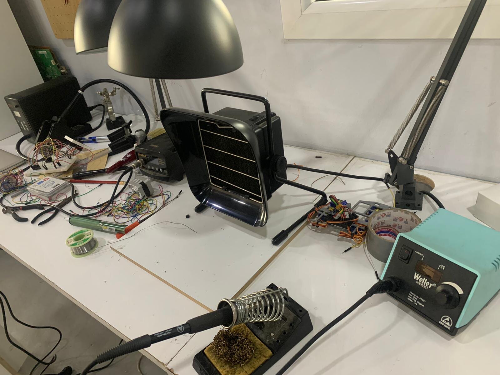
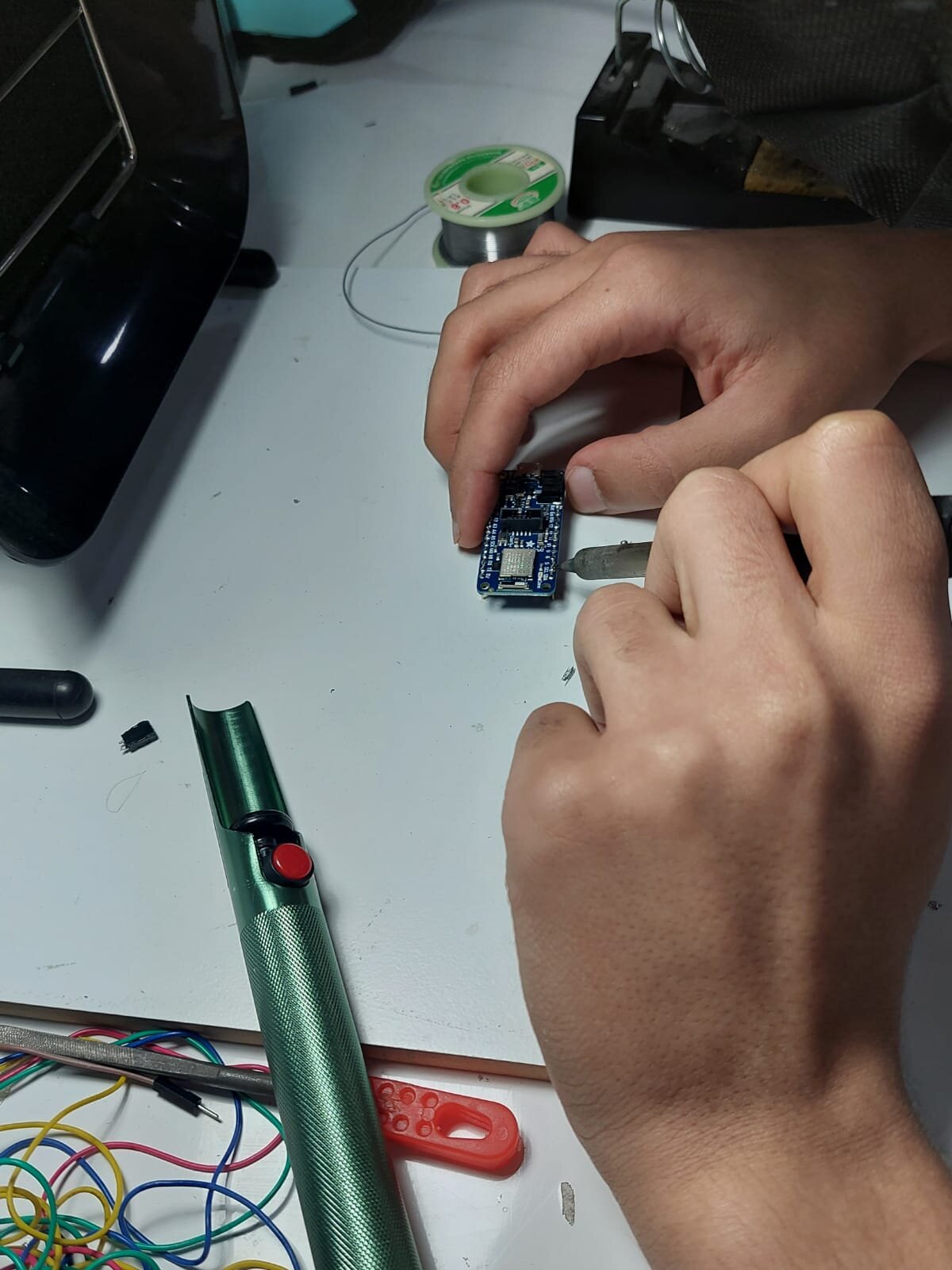
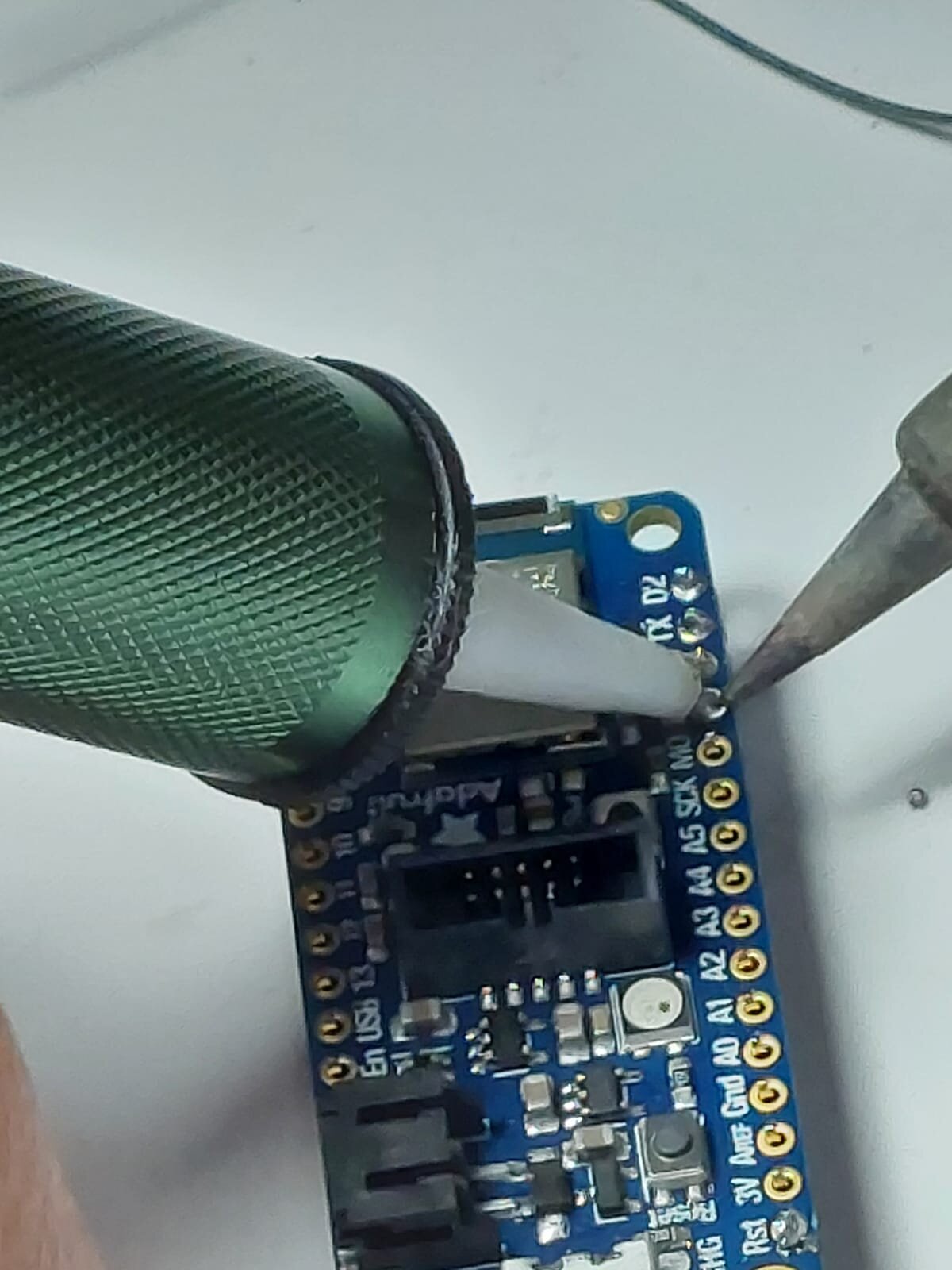
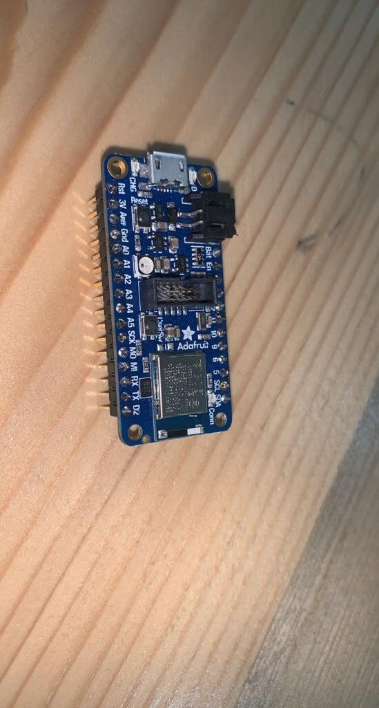
Solidification
We attached the pins to the adafruit by melting a material that will act as glue we used heating pen also and a sponge to clean the heating pen. The welding process happens very fast sometimes you will get off the road so there is a tool to take of whatever wrong you have done by re melting it the following image summarize the setup.