4. Embedded Programming
The learning outcomes of this week is to identify relevant information in a microcontroller datasheet, and implement programming protocols.
What is Embedded Programming
Embedded programming is a specific type of programming that supports the creation of digital based devices. Essentially, it involves programming small computers (microcontrollers) that drive devices. In terms of its practical implementation, embedded programming is useful in the design of software for automotive features like thermostats and handheld games.
A microcontroller is like a basic computer it is much simpler and has much less power than even the basic PC and used to implement certain tasks.
Group Assignment
We were given a microcontroller “Arduino MKR Wifi 1010” and tasked us to search for the following questions:
What’s the name and type of the microcontroller?
Arduino MKR WIFI 1010
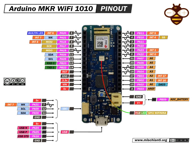
How Many pins does your microcontroller have?
it has a total of 28 pins: 8 digital I/O pins 7 analog input pins 1 analog output pins 13 PMW pins
What are the types of pins your microcontroller has?
Arduino MKR WIFI 1010 - Analog Output Pins - PWM Pins - External Interrupts
What type of sensors does your microcontroller have? (if any)
There are no sensors in the microcontroller pin itself but you can connect the following sensors: analog, digital and I2C sensor
What type of languages you can program it with? C++ by Arduino IDE
Link of microcontroller comparsion table
Individual Assignment
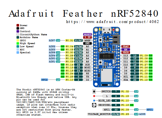
For the individual assignment we were given a task to test a microcontroller , it is Adafruit nrf52840. We test blinking the light with three challanges easy , medium and hard. this is the datasheet of the microcontroller
It has 16 pins and they are Power pins, Logic pins, Analog pins and BDM pins.
Types of sensor the microcontroller have
1- ST Micro series 9-DOF motion.
2- APDS9960 Proximity, light, color, and Gesture Sensor.
3- PDM Microphone sound sensor
4- SHT Humidity
5- BMP280 temperature and barometric pressure/altitude
Types of programming language the microcontroller supports
1- Bluefruit LE Connect
2- Bluefruit LE Connect OS X
3- Make Code
4- C++
5- Python
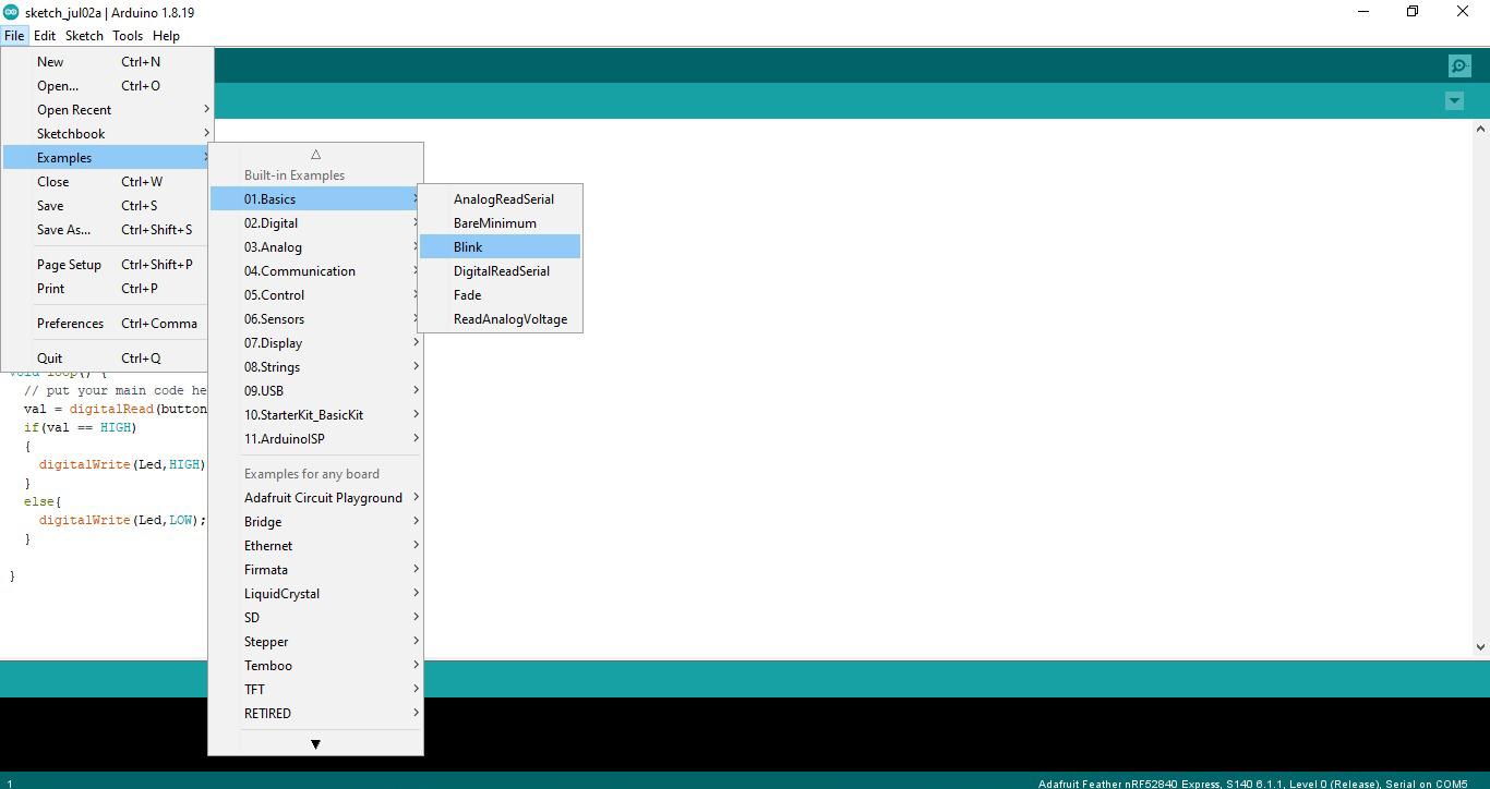
First we had to download Arduino IDE from Arduino formal website Don’t be fooled and install Arduino 2.0 beta version because it’s bad for using , just download the common one haha. Then, there are basic steps you have to follow for microcontroller “Adafruit nrf52840” setup.
Microcontroller setup steps
1- Download and install the Arduino IDE(At least **v1.8** ) 2- Go into Preferences 3- Add https://adafruit.github.io/arduino-board-index/package_adafruit_index.json as an **'Additional Board Manager URL' 4- Restart the Arduino IDE 5- Open the Boards Manager option from the Tools -> Board menu and install 'Adafruit nRF52 by Adafruit' (see image below) 
After doing the setup I tried one of basic applications “Blink” as example to test my microcontroller “Adafruit nrf52840”
/*
  Blink

  Turns an LED on for one second, then off for one second, repeatedly.

  Most Arduinos have an on-board LED you can control. On the UNO, MEGA and ZERO
  it is attached to digital pin 13, on MKR1000 on pin 6. LED_BUILTIN is set to
  the correct LED pin independent of which board is used.
  If you want to know what pin the on-board LED is connected to on your Arduino
  model, check the Technical Specs of your board at:
  https://www.arduino.cc/en/Main/Products

  modified 8 May 2014
  by Scott Fitzgerald
  modified 2 Sep 2016
  by Arturo Guadalupi
  modified 8 Sep 2016
  by Colby Newman

  This example code is in the public domain.

  https://www.arduino.cc/en/Tutorial/BuiltInExamples/Blink
*/

// the setup function runs once when you press reset or power the board
void setup() {
  // initialize digital pin LED_BUILTIN as an output.
  pinMode(LED_BUILTIN, OUTPUT);
}

// the loop function runs over and over again forever
void loop() {
  digitalWrite(LED_BUILTIN, HIGH);   // turn the LED on (HIGH is the voltage level)
  delay(1000);                       // wait for a second
  digitalWrite(LED_BUILTIN, LOW);    // turn the LED off by making the voltage LOW
  delay(1000);                       // wait for a second
}
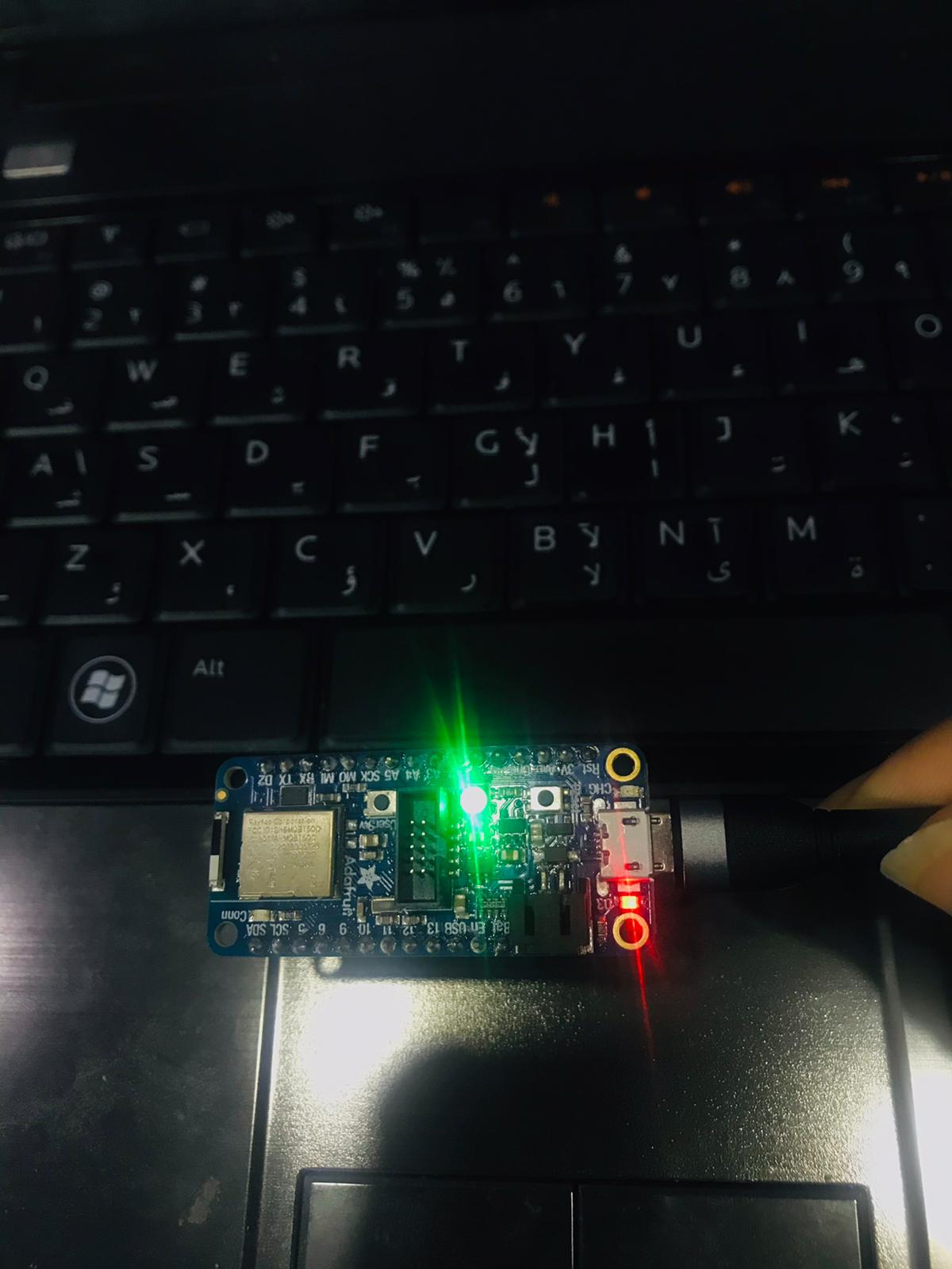
Then , I controlled LED light by adding ‘HIGH’ output and 500 milisecond.
## How code structure works ?
In the IDE there are two functions void setup and void loop.
- void setup() : is a function that you create at the top of each program. Inside the curly brackets is the code that you want to run one time as soon as the program starts running
- void loop(): another function so the code runs over and over as long as the microcontroller s turned on
- There are different types of input&output functions used: pinMode() , digitalRead(), digitalWrite(), analogRead() and analogWrite(). The one that is used to blink the internal LED is pinMode(). The pinMode() function has two arguments: one is the pin number, and the other is the mode of the pin
- delay() is a simple function used to pause programs for miliseconds.
Controlling by different timings.
TinkerCAD Tutorial
TinkerCAD allows you simulate microcontrollers which is useful for beginners. To simulate choose TinkerCAD circuits, then drag and drop Arduino Uno R3. At the top right corner press on code, the code is pre-made so after that you immediately start simulation.
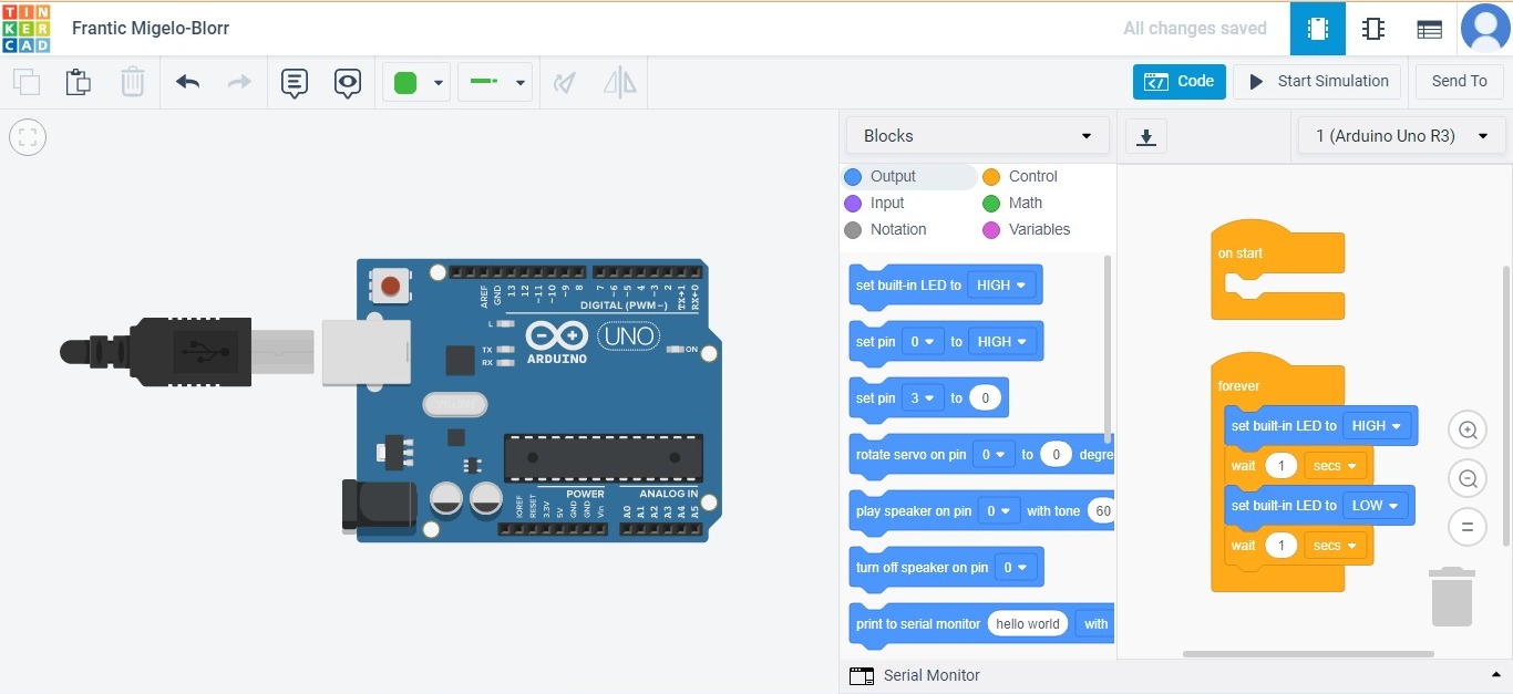
Initial pre-made simulation
Then we we were introduced to Morse Code, Morse Code is representing letters of alphabet, numbers and punctuation marks by an arrangement of dots, dashes and spaces. The codes are transmitted as electrical pulses represented as signals like flashing light.
How Morsecode works? . = Low -= High
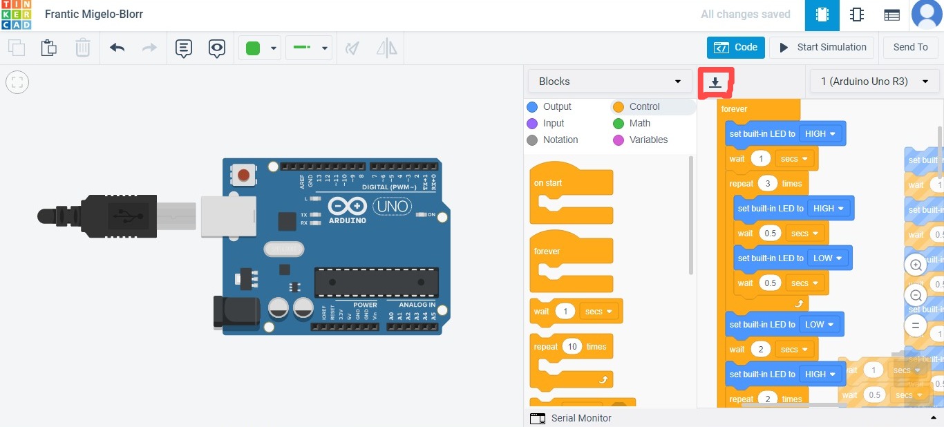
For given example I chose the word ‘book’ and put it in code blocks based on representation that we were given in class.
dot = 0.5 sec dash = 1 sec gap between dot and dash = 0.5 sec (off) gap between letter = 2 sec off
‘book’ in Morsecode -… — — -.-
1 sec 0.5 sec (off) 0.5 sec 0.5 sec (off) 0.5 sec 0.5 sec (off) 0.5 sec 2 sec off
1 sec 0.5 sec (off) 1 sec 0.5 sec (off) 1 sec 2 sec off
1 sec 0.5 sec (off) 1 sec 0.5 sec (off) 1 sec 2 sec off
1 sec 0.5 sec (off) 0.5 sec 0.5 sec (off) 1 sec
I applied the code in drag and drop bar then downloaded the code to test it in my by Adafruit nrf5840”
The Code
// C++ code
//
int counter;

int counter2;

int counter3;

void setup()
{
 pinMode(LED_BUILTIN, OUTPUT);
}

void loop()
{
 digitalWrite(LED_BUILTIN, HIGH);
 delay(1000); // Wait for 1000 millisecond(s)
 for (counter = 0; counter < 3; ++counter) {
   digitalWrite(LED_BUILTIN, HIGH);
   delay(500); // Wait for 500 millisecond(s)
   digitalWrite(LED_BUILTIN, LOW);
   delay(500); // Wait for 500 millisecond(s)
 }
 digitalWrite(LED_BUILTIN, LOW);
 delay(2000); // Wait for 2000 millisecond(s)
 digitalWrite(LED_BUILTIN, HIGH);
 for (counter2 = 0; counter2 < 2; ++counter2) {
   delay(1000); // Wait for 1000 millisecond(s)
   digitalWrite(LED_BUILTIN, LOW);
   delay(500); // Wait for 500 millisecond(s)
 }
 digitalWrite(LED_BUILTIN, HIGH);
 delay(1000); // Wait for 1000 millisecond(s)
 digitalWrite(LED_BUILTIN, LOW);
 delay(2000); // Wait for 2000 millisecond(s)
 for (counter3 = 0; counter3 < 2; ++counter3) {
   digitalWrite(LED_BUILTIN, HIGH);
   delay(1000); // Wait for 1000 millisecond(s)
   digitalWrite(LED_BUILTIN, LOW);
   delay(500); // Wait for 500 millisecond(s)
 }
 digitalWrite(LED_BUILTIN, HIGH);
 delay(1000); // Wait for 1000 millisecond(s)
 digitalWrite(LED_BUILTIN, LOW);
 delay(2000); // Wait for 2000 millisecond(s)
 digitalWrite(LED_BUILTIN, HIGH);
 delay(1000); // Wait for 1000 millisecond(s)
 digitalWrite(LED_BUILTIN, LOW);
 delay(500); // Wait for 500 millisecond(s)
 digitalWrite(LED_BUILTIN, HIGH);
 delay(500); // Wait for 500 millisecond(s)
 digitalWrite(LED_BUILTIN, LOW);
 delay(500); // Wait for 500 millisecond(s)
 digitalWrite(LED_BUILTIN, HIGH);
 delay(1000); // Wait for 1000 millisecond(s)
}
Challenges
Easy
Prompt: Blink your led but have your blink delay periods be randomized values between 1 second and 5 seconds
The solution: Apply the steps 1- Use TinkerCAD to add code brick that will allow you apply given “random delays between 1 and 5 second”
2- Simulate tp preview the code
3- Download the code to Arduino IDE then load it onto your microcontroller
4- The result “Tdaa !”
// C++ code
  //
  void setup()
  {
    pinMode(LED_BUILTIN, OUTPUT);
  }

  void loop()
  {
    digitalWrite(LED_BUILTIN, HIGH);
    delay(1000 * random(1, 5 + 1)); // Wait for 1000 * random(1, 5 + 1) millisecond(s)
    digitalWrite(LED_BUILTIN, LOW);
    delay(1000 * random(1, 5 + 1)); // Wait for 1000 * random(1, 5 + 1) millisecond(s)
  }
Medium
Prompt : pre code your microcontroller to send a Morse code 1 word message and challenge a friend, family member, your colleagues or your instructor to figure it out.
dot = 0.5 second light on.
dash=1 second light on.
gap between dots and dashes=0.5 second light off.
gap between letters=2 second light off
Hard
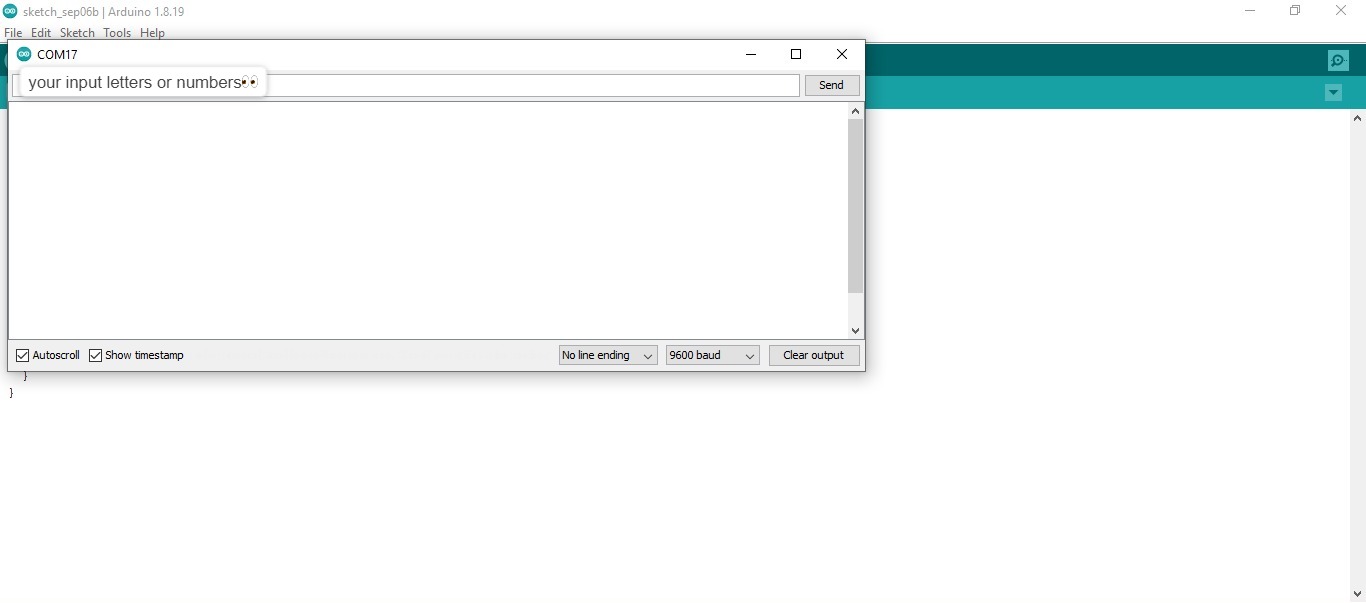
Prompt: you select the duration of the light being on and off while the program is running by entering it in the serial monitor. Write a code that takes the data from the serial monitor and delays by that amount of time.
Solution: - apply the same steps - To write code needed I searched for resources to help me and modified a bit to reach final code shown below
int incomingByte = 0; // for incoming serial data

void setup() {
  Serial.begin(9600); // opens serial port, sets data rate to 9600 bps
}

void loop() {
  // check if data is available
  if (Serial.available() > 0) {
    // read the incoming byte:
    incomingByte = Serial.read();

    // prints the received data
    Serial.print("I received: ");
    Serial.println((char)incomingByte);
  }
}
I wrote in serial monitor random things then it is translated as flashing light
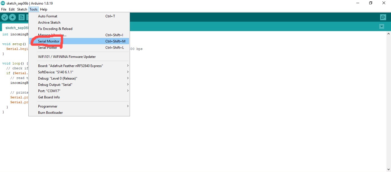
How to open the Serial Monitor?