7. Input & Output device
This week I learned how to make up thing from connecting circuit and control it by software that do specific operation.
# Input and Output
Input devices : Input device enables the user to send data, information or control signals to a computer.
Output devices : recieves data from the computer or microcontroller which is known as small PC.
Analog vs Digital
Analog signal is time-varying means the voltage changes based on reading it gets. For example, sound sensor will send out high dim light when voice gets louder and vice versa.
While digital, it gives either high or low voltage no situation in between. For example, sensor either light on or off based on distance if far or close.
Individual Assignment
We were tasked to measure something with sensors in lab connected with microcontroller then try to include more changes to see how input and output works all togather with the results.

Input device 1: Sound detection device
Sound sensor detects sound waves through its intensity and converting it to electrical signals
I tested sound sensor and by following the datasheet I could recognize how to connect sound sensor pins with microcontroller. The Datasheet !
following the datasheet I try to know the pins and its uses, first you have to know which are the input/output pins in the device and connect it to the microcontroller, the microcontroller I use is Adafruit I connected VCC +5 and GND from sensor to Adafruit pins of in/out. Then for the output pin of the sensor I connected it to Analog pin 13 you could choose any number since it is analog.
code
code part is the most interesting one, you have to know three parts the variables, void setup() and void loop() the variables are defined based on pin numbers, Led is meant by the internal small Led of the Adafruit microcontroller. val variable equal zero because will be made with if statement, once it detects the sound and read it as data (analog) will make Led intensity high.
int Led =12;
int buttonpin= 13;
int val = 0;


void setup() {

  // put your setup code here, to run once:
  pinMode(Led, OUTPUT);
  pinMode(buttonpin, INPUT);

}

void loop() {
  // put your main code here, to run repeatedly:
  val = digitalRead(buttonpin);
  if(val == HIGH)
  {
    digitalWrite(Led,HIGH);
  }
  else{
    digitalWrite(Led,LOW);
  }

}
Input device 2: Servo motor
A servo motor is a device that rotate with great precision. This type of motor consists of a control circuit that provides feedback on the current position of the motor shaft, this feedback allows the servo motors to rotate with great precision .It is just made up of a simple motor which runs through a servo mechanism. If motor is powered by a DC power supply then it is called DC servo motor, and if it is AC-powered motor then it is called AC servo motor.
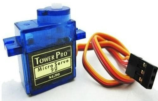
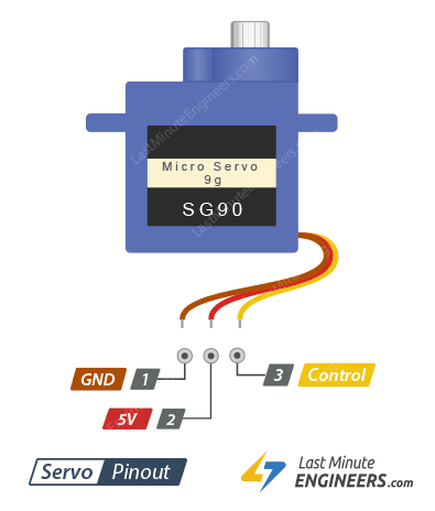
From the datasheet we connect GND and VCC to our microcontroller
// Include the Servo library
#include <Servo.h>
// Declare the Servo pin
Servo motor;
int servoPin=9;
// Create a servo object
Servo Servo1;
void setup() {
   // We need to attach the servo to the used pin number
   motor.attach(9);
   motor.write(18);
}
void loop(){
  for(servoPin=0;servoPin<180;servoPin++){
    motor.write(servoPin);
    delay(10);
  }

}
I tested it and worked, to see the rotation output change the angle in for loop and try yourself !
Problems encountred
1- when trying to test sound sensor I did not see any output then I realized that sound must be so loud and near the microcontroller so the sound waves are clearly detected and intensity of light becomes higher.
2- Servo motor first did not give any output, so I checked my wirings and code, then I realized that my wiring are flipped so rewired again and refreshed my ARDUINO IDE so it load code from the start.
Tips when it does not work
1- Check the portal and Board.
2- Check your wirings if they are in the right pins, and if wired pins are the same you defined in your code.
3- Load code again and test it.