3. Computer controlled cutting
This week we were introduced to one of fabrication tools “CNC” stands for Computer Controlled Cutting.Computer Controlled Cutting is a fabrication process that uses a thin, focused, laser beam to cut materials into custom designs, patterns, and shapes as specified by a designer.
Laser Cutter
Laser cutter is a narrow piece of computer control that cut materials for specific designs, patterns, and forms defined by a designer using softwares. It works with variety of materials, including wood, glass, paper,metal and plastic.It can also produce complicated pieces without the use of a custom-designed tool.
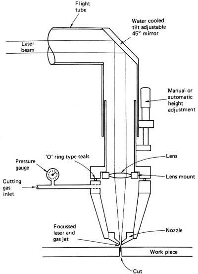
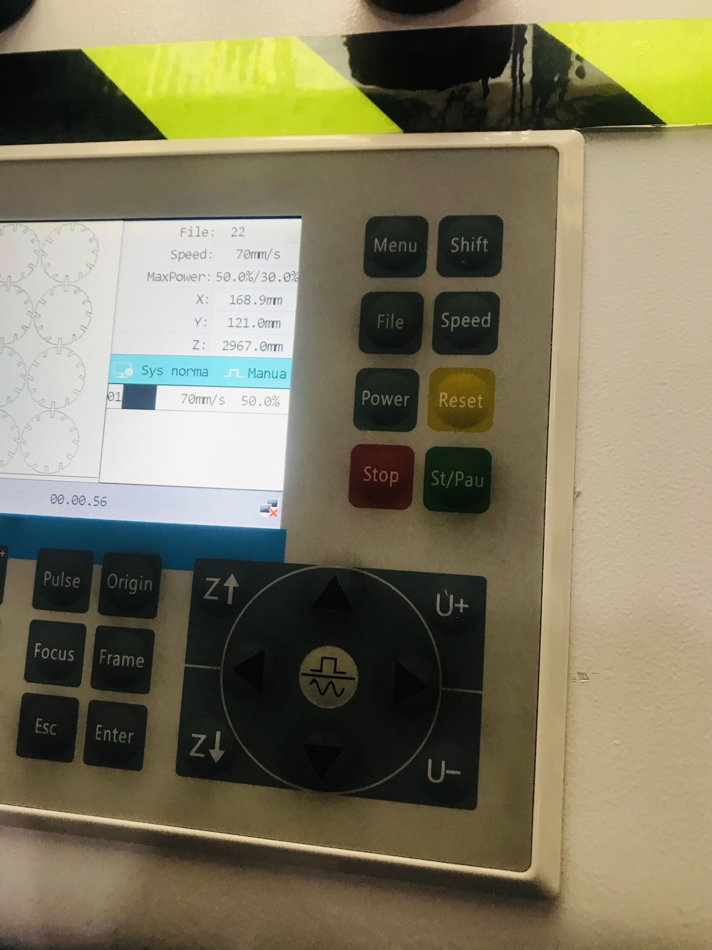
image of the laser cutter
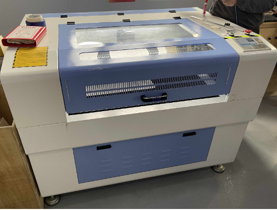
this the machine in the lab.
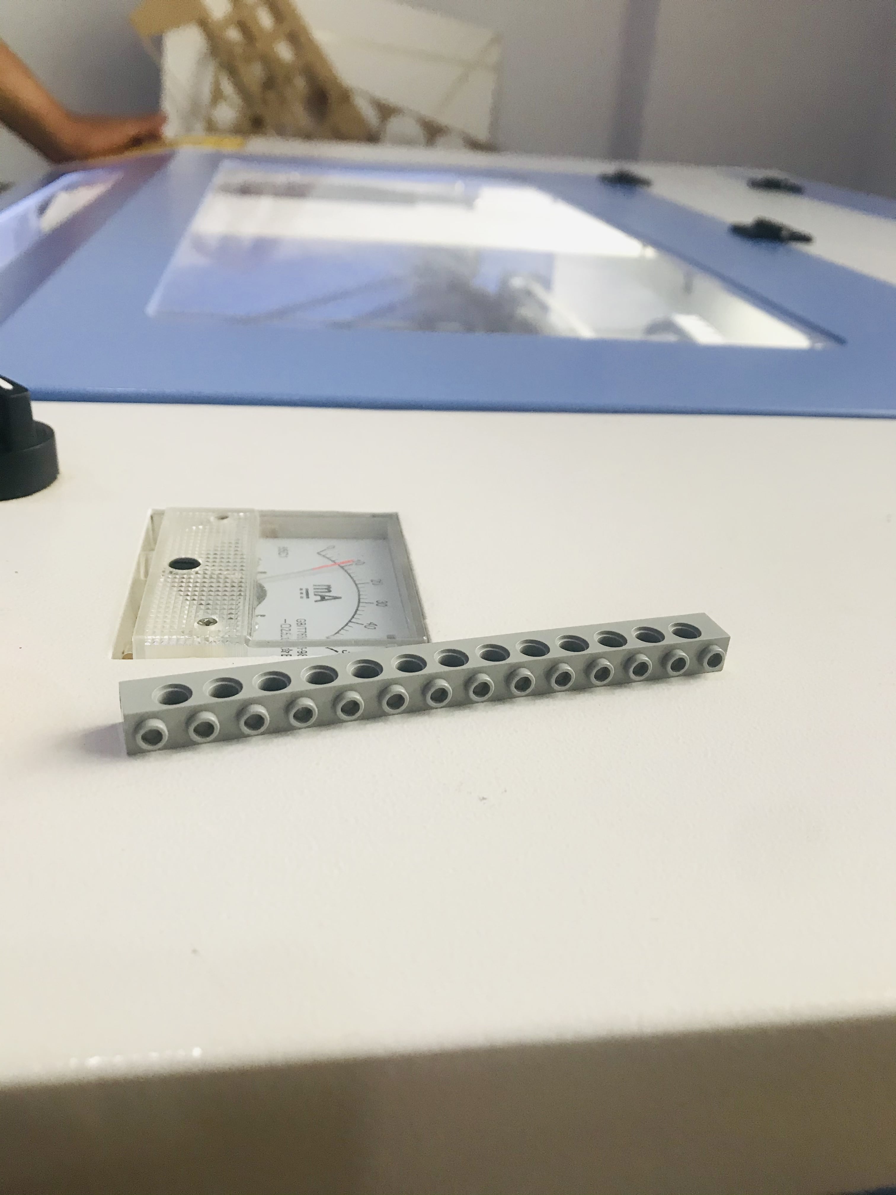 this is to adjust the level needed to cut your design
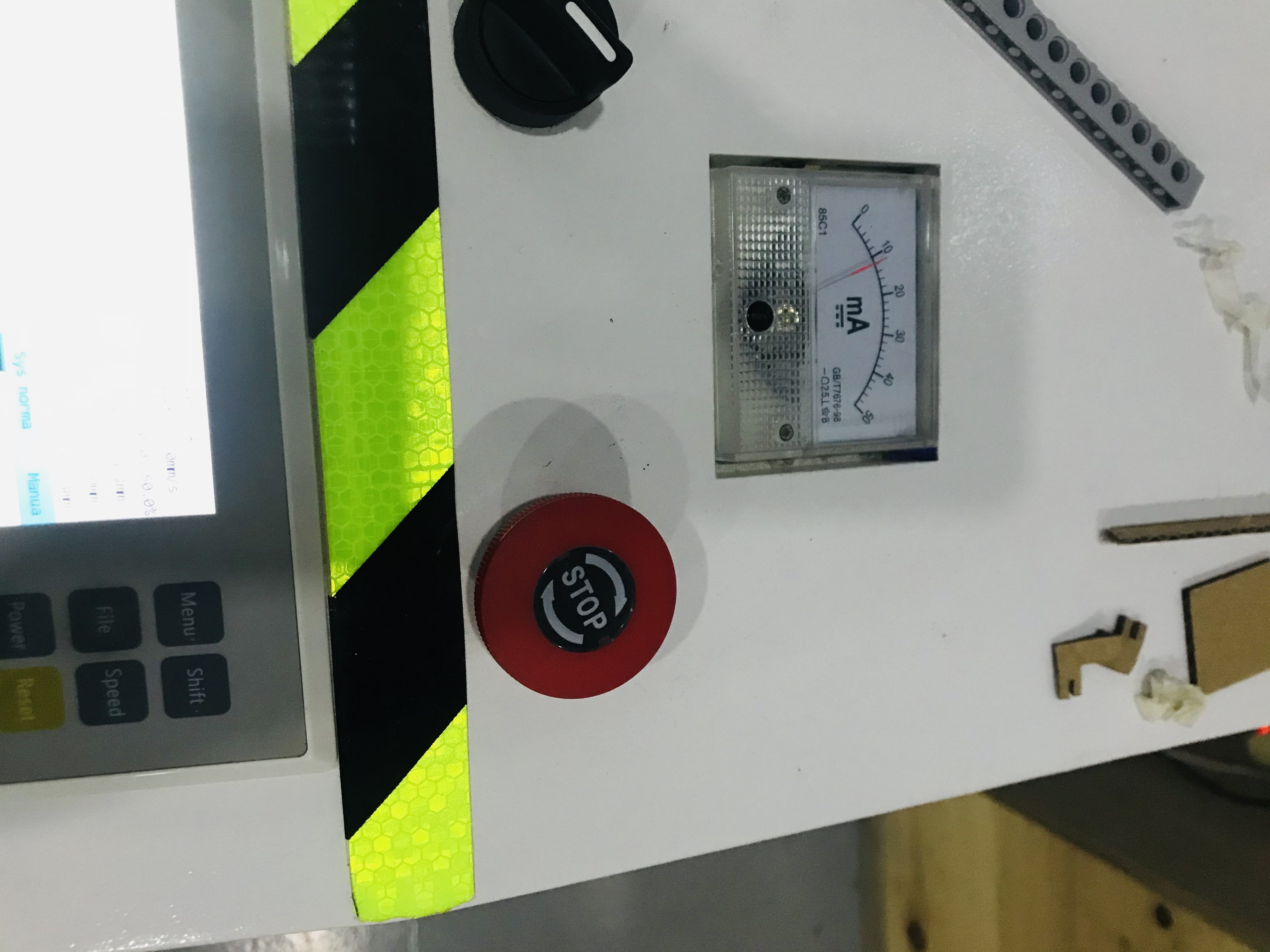 an emergency button
Group Assignment
For group assignment there are test procedures need to be done on the machine which they are lasercutter’s focus, power, speed, rate, kerf, and joint clearance. 1- Joints: means joints on the design when you overlap them they have to fit on each other not too big that make them fall and not too small that fails to overlap them.
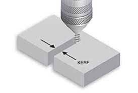
2- Kerf: is the amount of material cut using the laser cutter. In Other words, it is the width of the laser flow that takes from the material while cutting.
3- Laser speed: The best speed the laser have to move to get results correctly without mistakes.
4- Laser power: means the best power that the laser can cut the material, not big that consume more gas orelse and not small that it can’t cut the material.
5- Laser focus: this is critical character of the machine is to ensure the maximum amount of available energy produced by the tube reaches the work piece it is the “focal point”. If you are “out of focus” then the machine will not cut as effectively, as you are lessening the effect of the beam on the part.
6- Laser clearance: To attach to two parametric construction kit, the size of the joint must be known to get the best fit.
This link has all detalied procedure attached with images that shows the whole process Click here !
My Parametric Design
There are mutliple softwares to conduct the design process, the one I used is Cuttle xyz ,it is a web-based application to design basic shapes and transform it into combined nice shapes using different tools , the ones I used are rotation repeat and boolean difference.

Cuttle xyz Logo
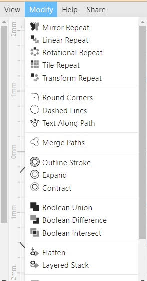
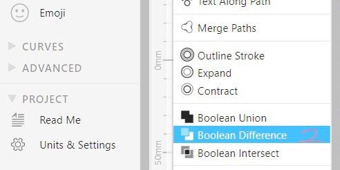
Here is the different tools can be used to create many different combined shapes
Steps I followed to create my design
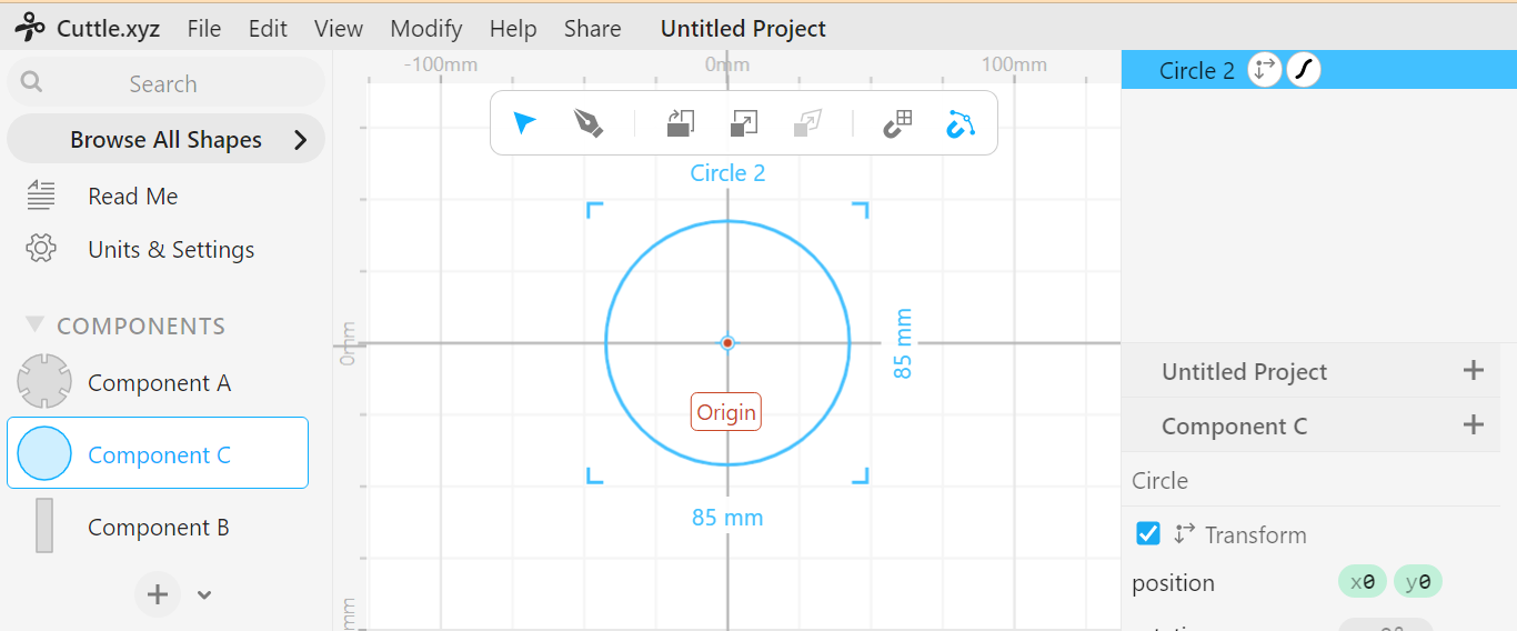
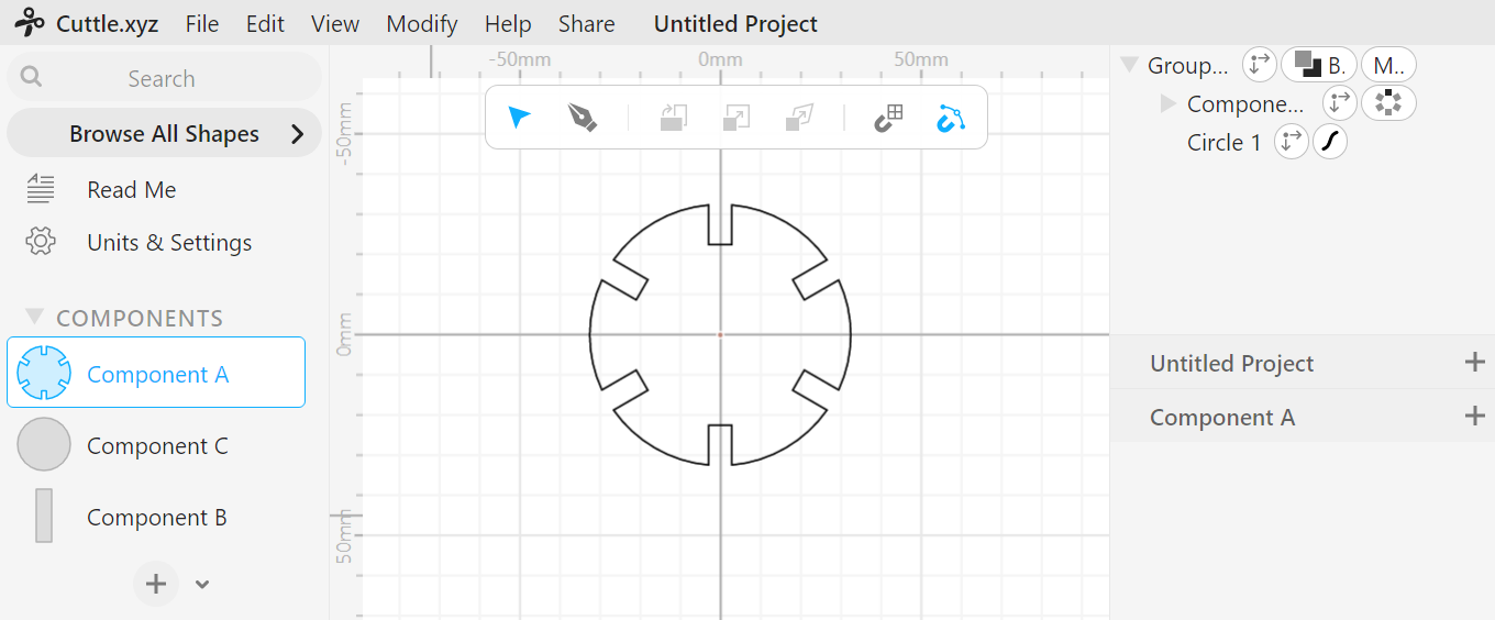
1- I started my design with circle shape labeld as compomnent ‘A’
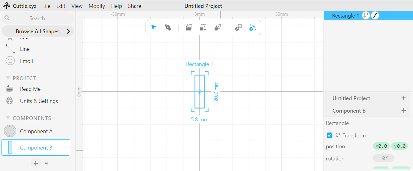
2- To combine with component ‘A’ I used rectangle as second shape that tools will be applied on.For constraints the instructor gave us a fixed measure 5.8 mm
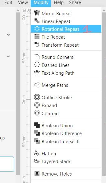
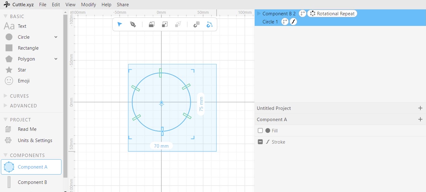
3- To apply the tools, by dragging and pulling component ‘B’ , I did rotation pattern and clicked on ‘Boolean Difference’
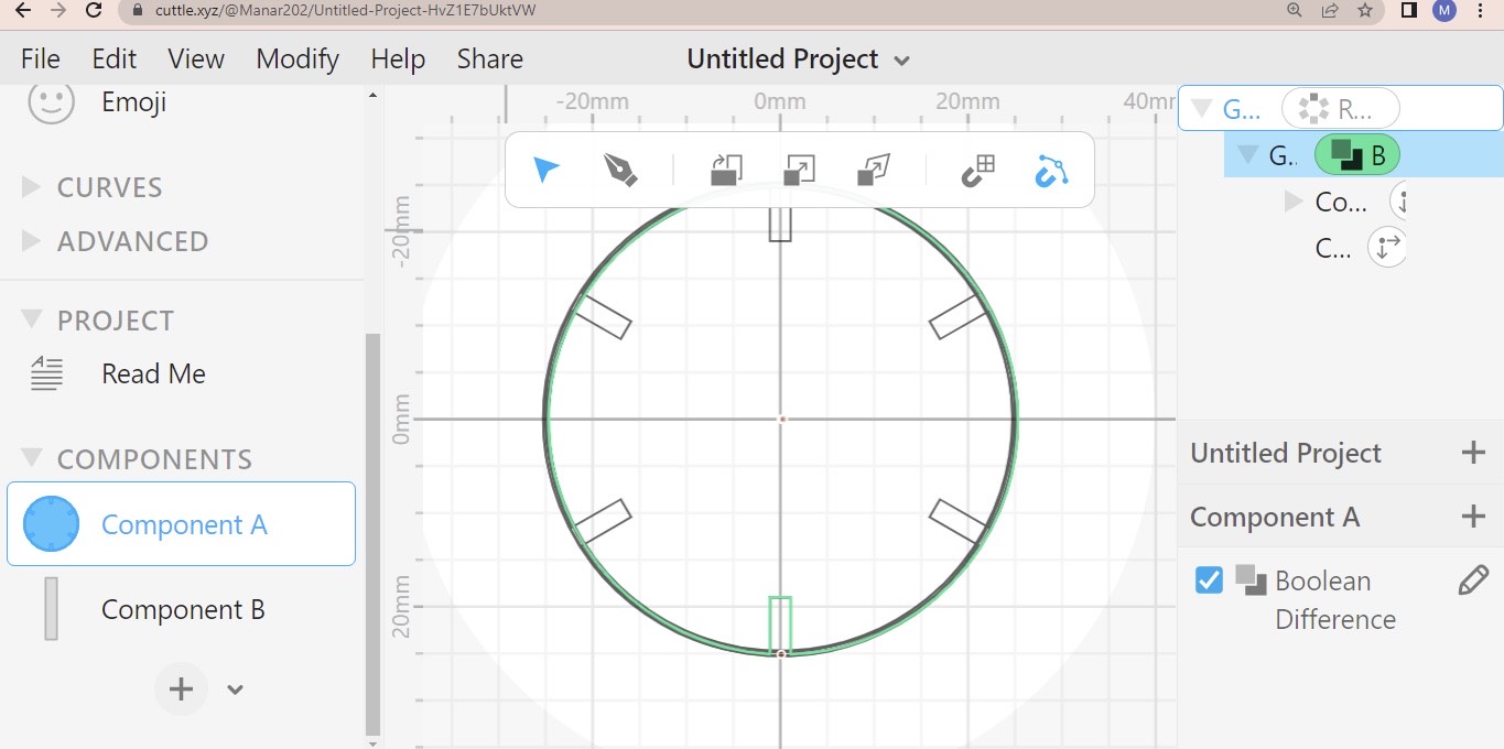
4- The result
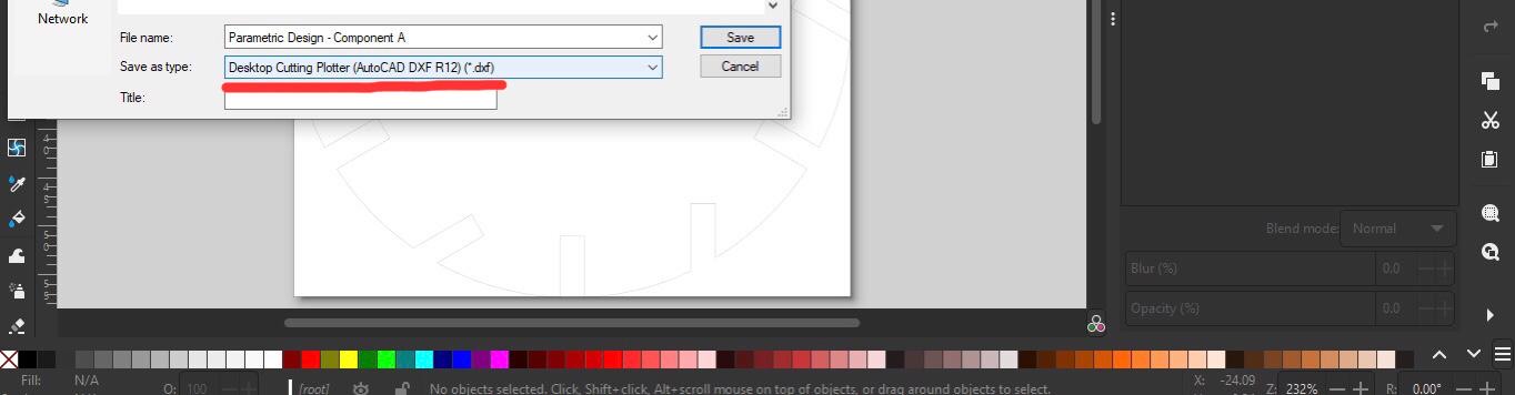
5- Then I exported the design as .SVG
6- For the design to be installed in RDWroks I had to convert it into .dxf by inkscape
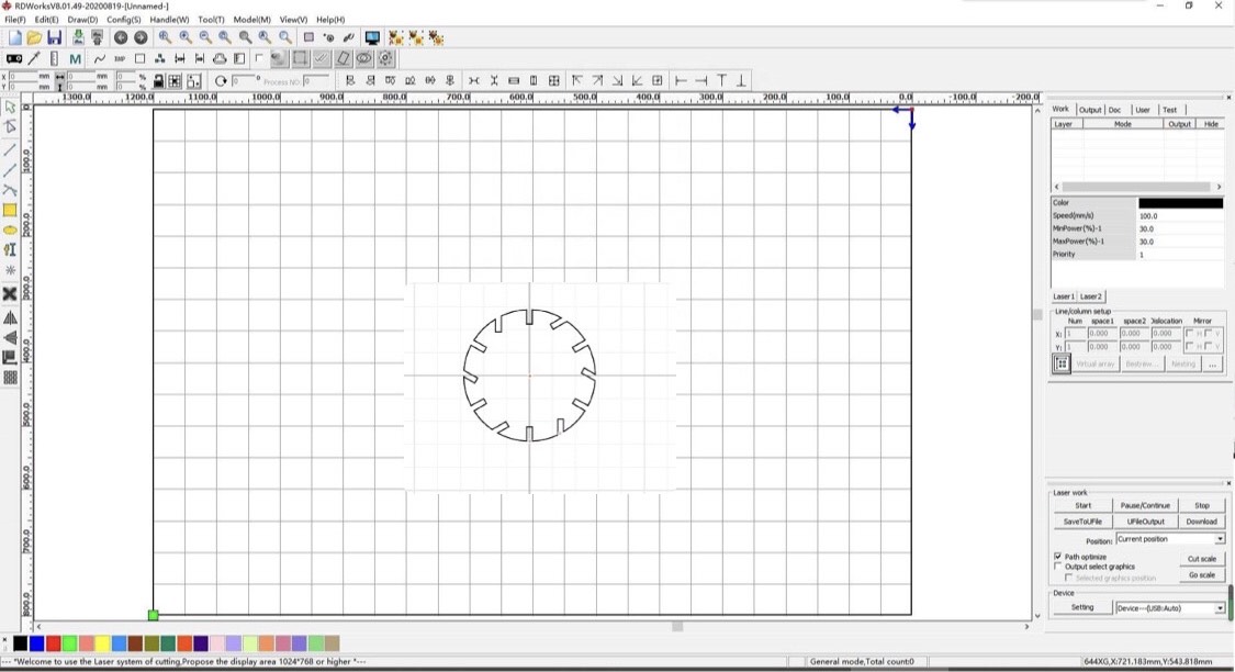
7- The Computer Aided Design used is RDWorks to be sent to the machine
example of another design
Note
I had an issue where constraints widen maybe because I resized my design in RDWorks but I continued the process when I informed the instructor
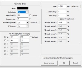
Before we send the design to machine, we assign the shown information. The speed is assigned to 70mm/s, and power is not changed the same as 50.
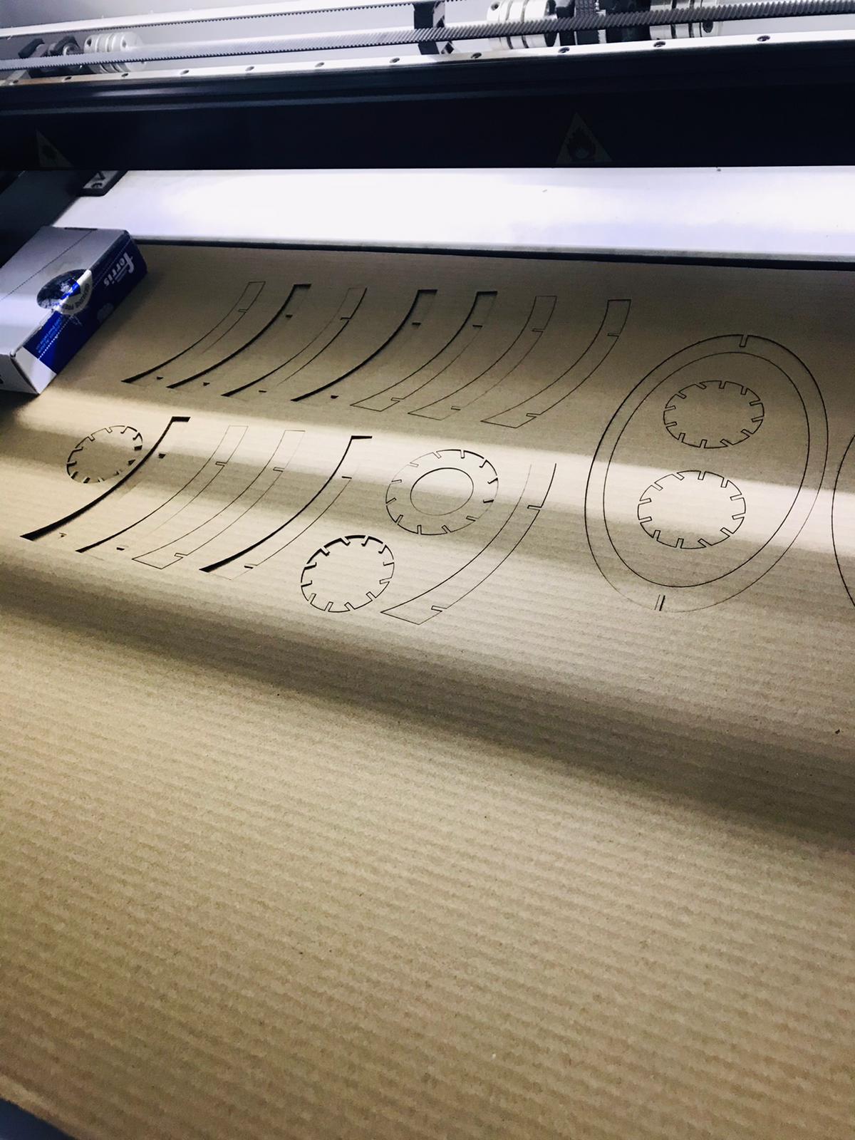
The laser cutter cutting off my design and colleague’s pieces
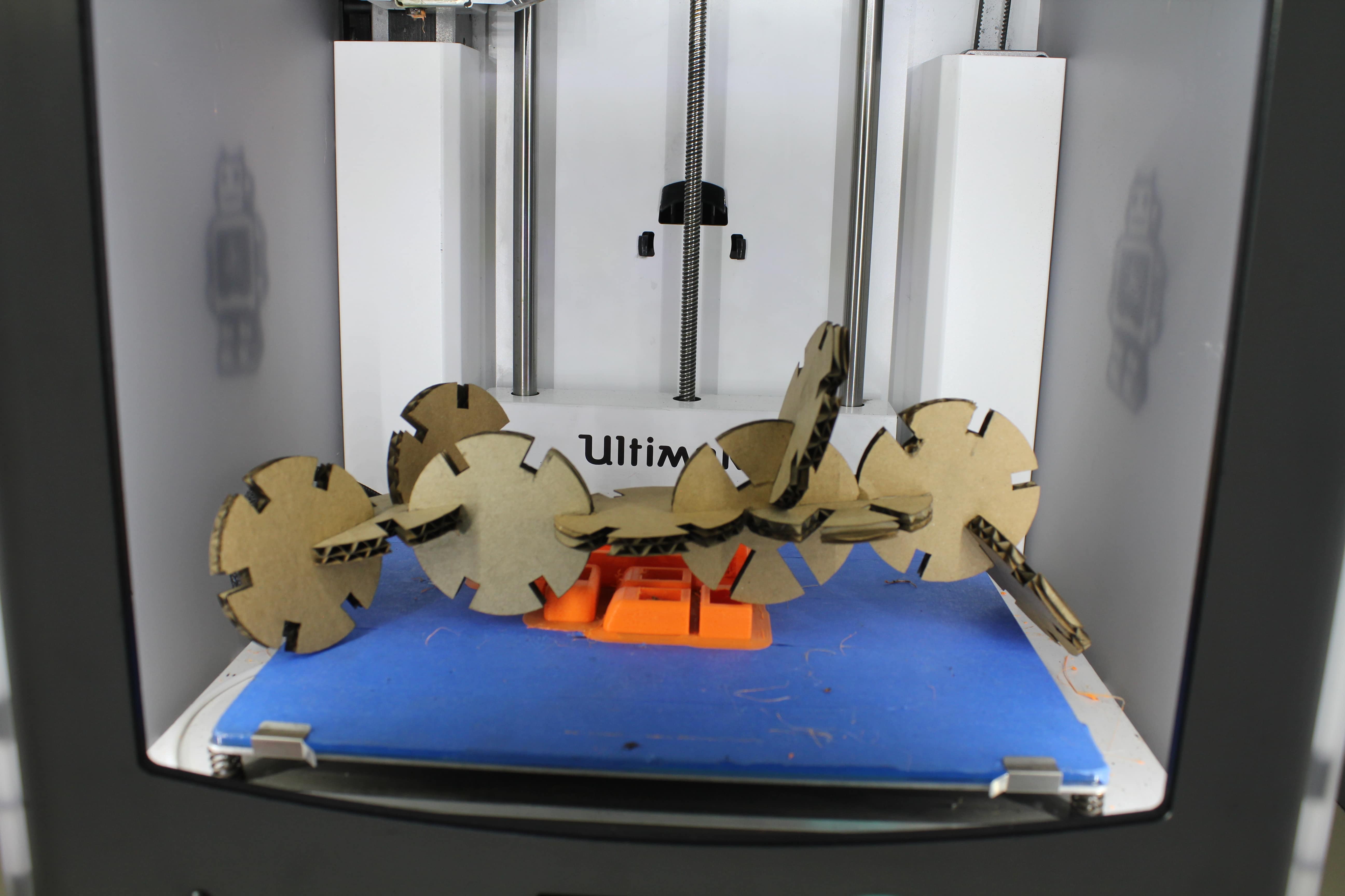
Heroshot of the design
Design file
Problems encountred in Cuttle xyz
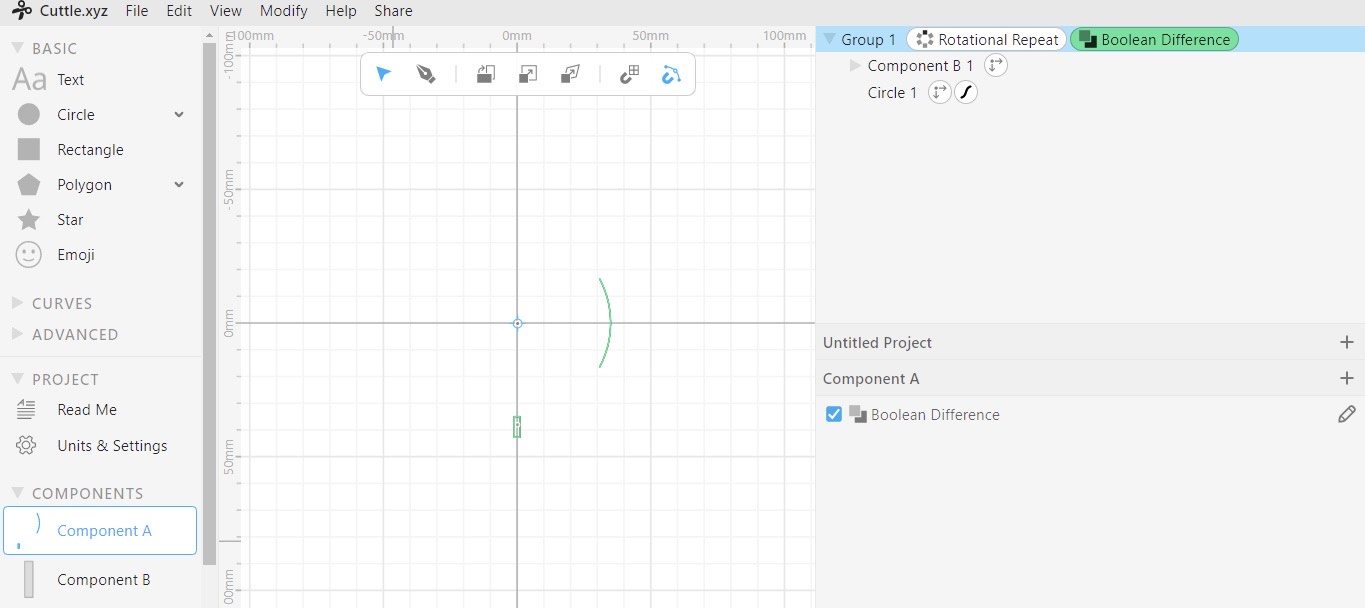
Sometimes Cuttle fails to create the desired shapes, when I was trying to get boolean difference, Cuttle created for me meaningless shape shown below:
To avoid this problem:
1- Make sure when you apply rotation pattern specify just the shape that will be rotated not two of them
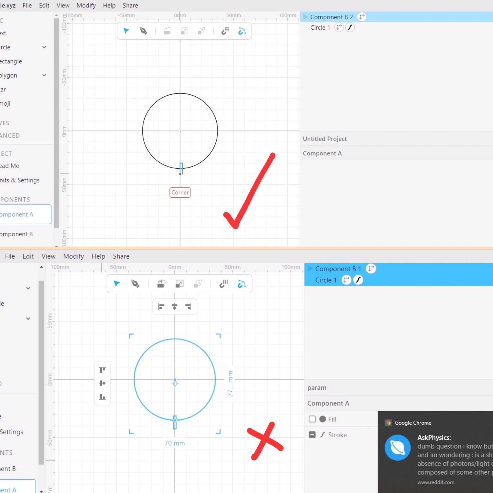
2- Then , when you apply boolean difference you have to specify the two shapes
3- And parametric design is created

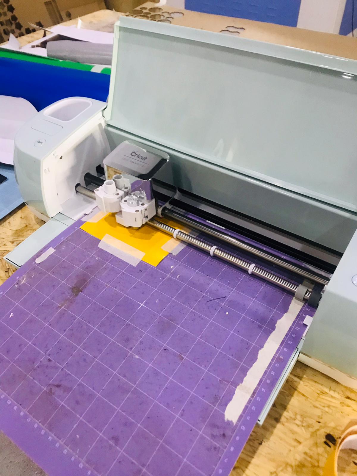
Vinyl Cutting
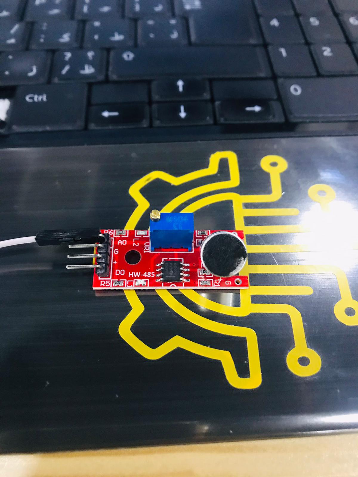
Vinyl cutters are mainly used to make stickers by using ‘Circuit’. I chose electronics design logo to be cut.
Steps on how to use Circuit steps
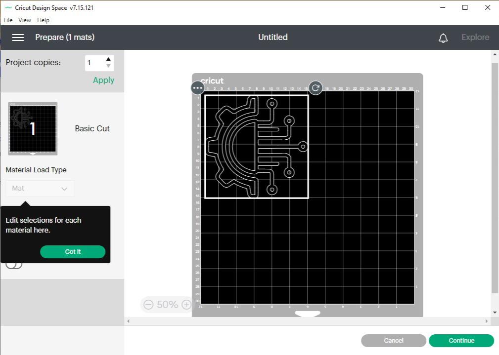
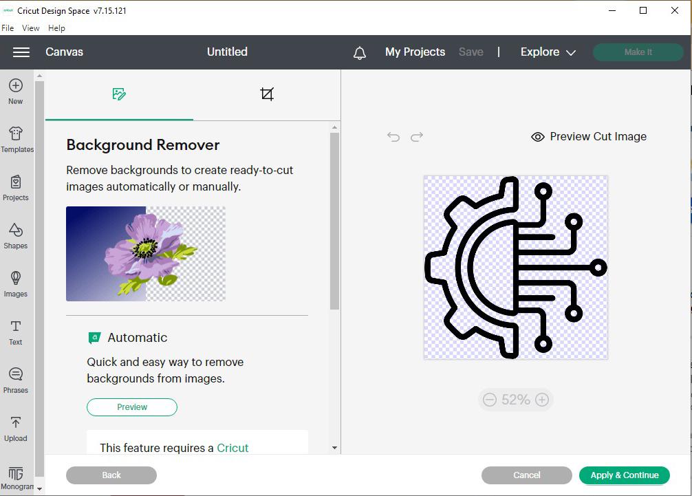
1- Download Circuit Design Space [Download](https://design.cricut.com/) 2- You could upload an image as .png, .jpg, .gif, .svg, .dxf, .heic or .bmp 3- Continue the instructions provided by the software 4- Then it will show option tas 'Backgroun Remover' so make sure to remove background to get a clean sticker 5- Proceed to print the sticker 6- Load the piece of vinyl into the machine, by placing the mat on the starting point on the device 7- When the design is cut remove vinyl extra that you won't nedd uding cutter 8- To position your sticker, put transparent paper on it then stick it onto any surface you'd like
I uploaded my design
Then sent it to canvas to resize it
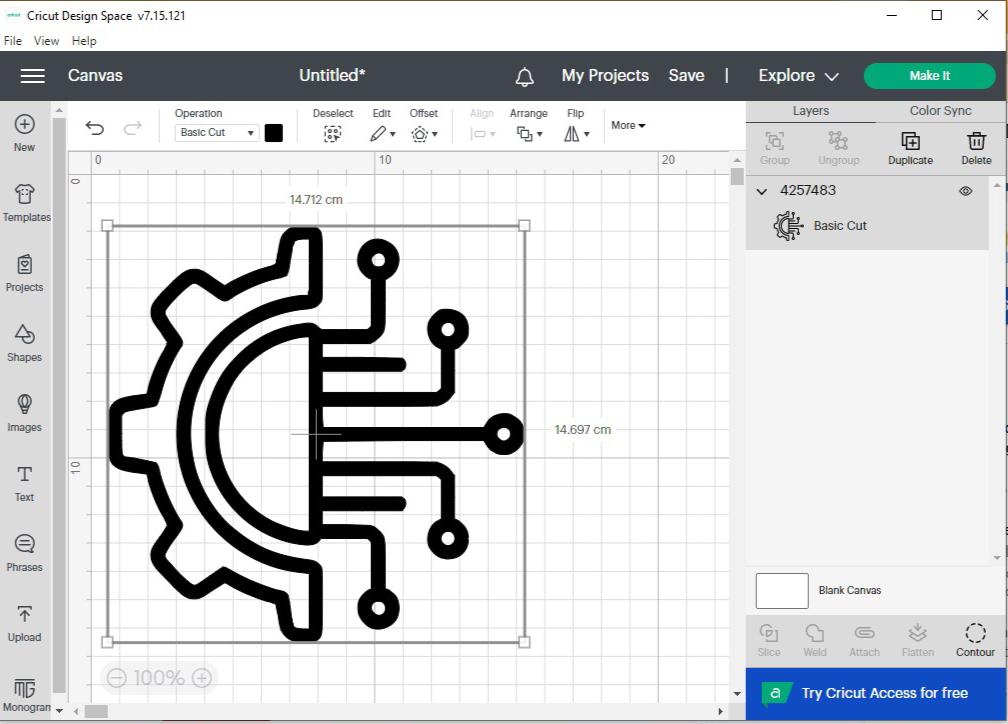
The selection area before printing