4. Embedded programming
This week I worked on embedded programming, we will use Arduino IDE.
Arduino IDE
We will use this software to program and code our microcontroller. First you need to download the software from the following link
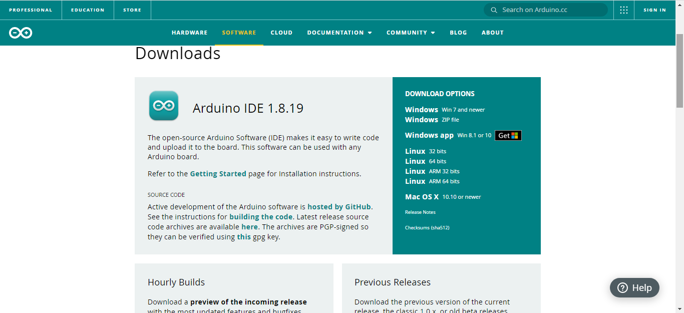
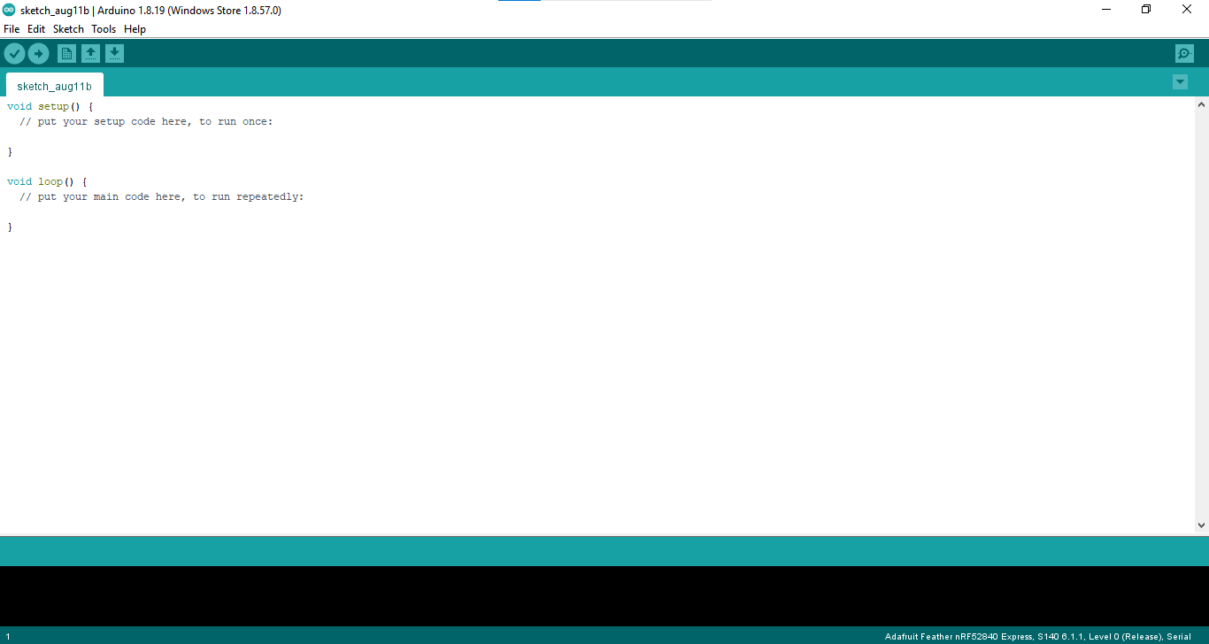
After its fully downloaded install the setup and run it
Setup your microcontroller
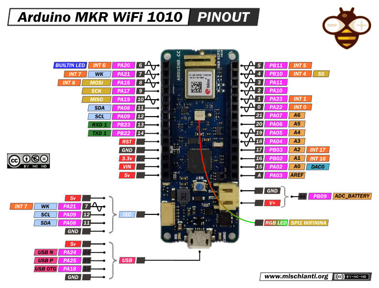
Mine was arduino MKR1010 and here is the datasheet for it
which is available already on Arduino IDE so we just needed to download the library of it
specifications of MKR1010
1-BOARD POWER SUPPLY (USB/VIN)= 5V
2-CIRCUIT OPERATING VOLTAGE= 3.3V
3-SUPPORTED BATTERY= Li-Po Single Cell, 3.7V, 1024mAh Minimum
4-DIGITAL I/O PINS= 8
5-PWM PINS= 13 (0 .. 8, 10, 12, 18 / A3, 19 / A4)
6-ANALOG INPUT PINS= 7 (ADC 8/10/12 bit)
7-ANALOG OUTPUT PINS= 1 (DAC 10 bit)
8-DC CURRENT PER I/O PIN= 7mA
9- it has 6 LED BUILTIN
MKR1010 PINOUT
what i learned
After reading the datasheet i learned that:
The MKR WiFi 1010 is a miniature sized module containing a SAMD21G18A Processor, the Nina W102 Module, a crypto chip (the ATECC508), and a 2MByte SPI Flash.
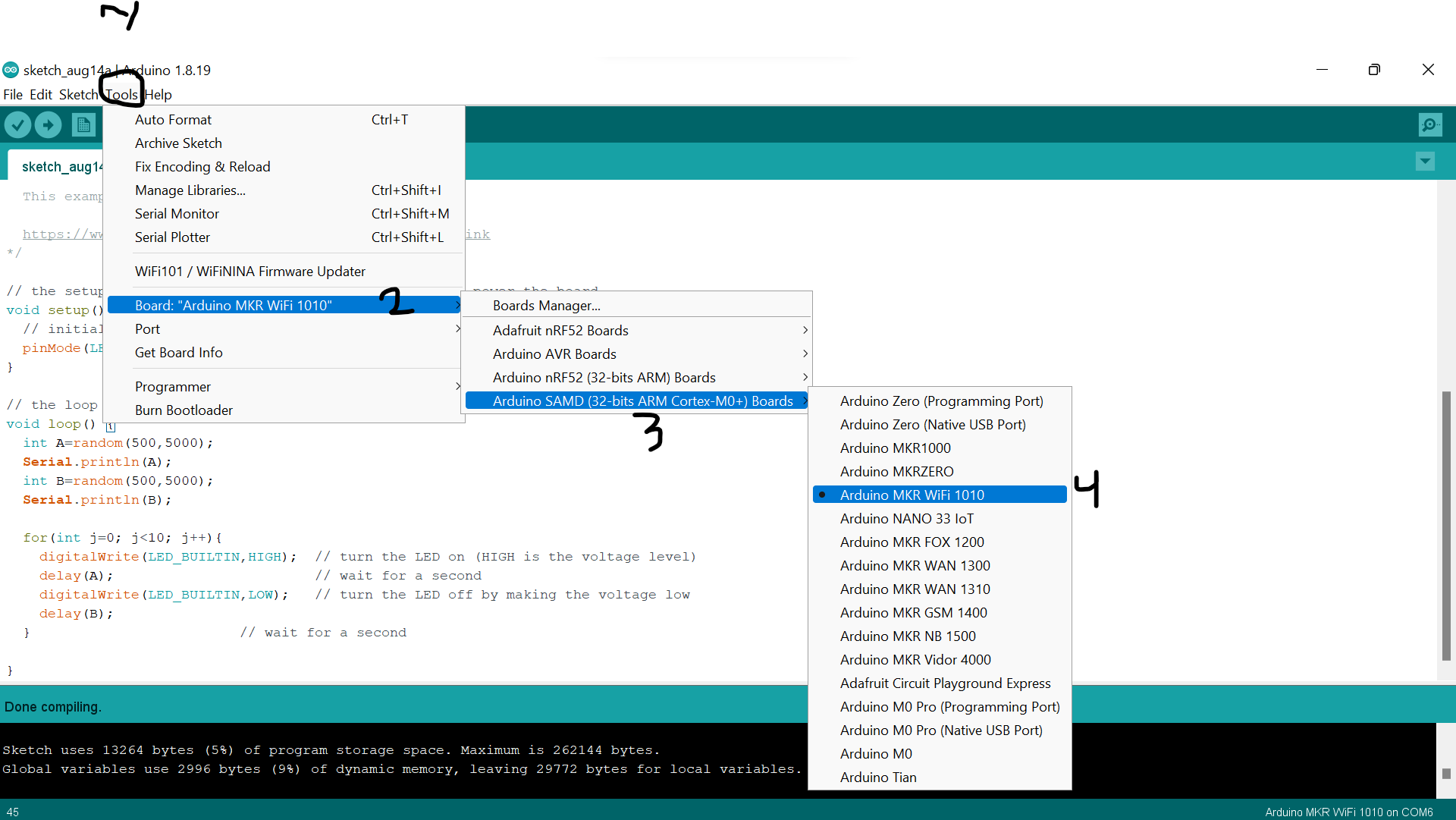
After that
Tools/Board/Board manager find ..... and install it, i already install it
Connect the microcontroller with USB and insert it to your laptop
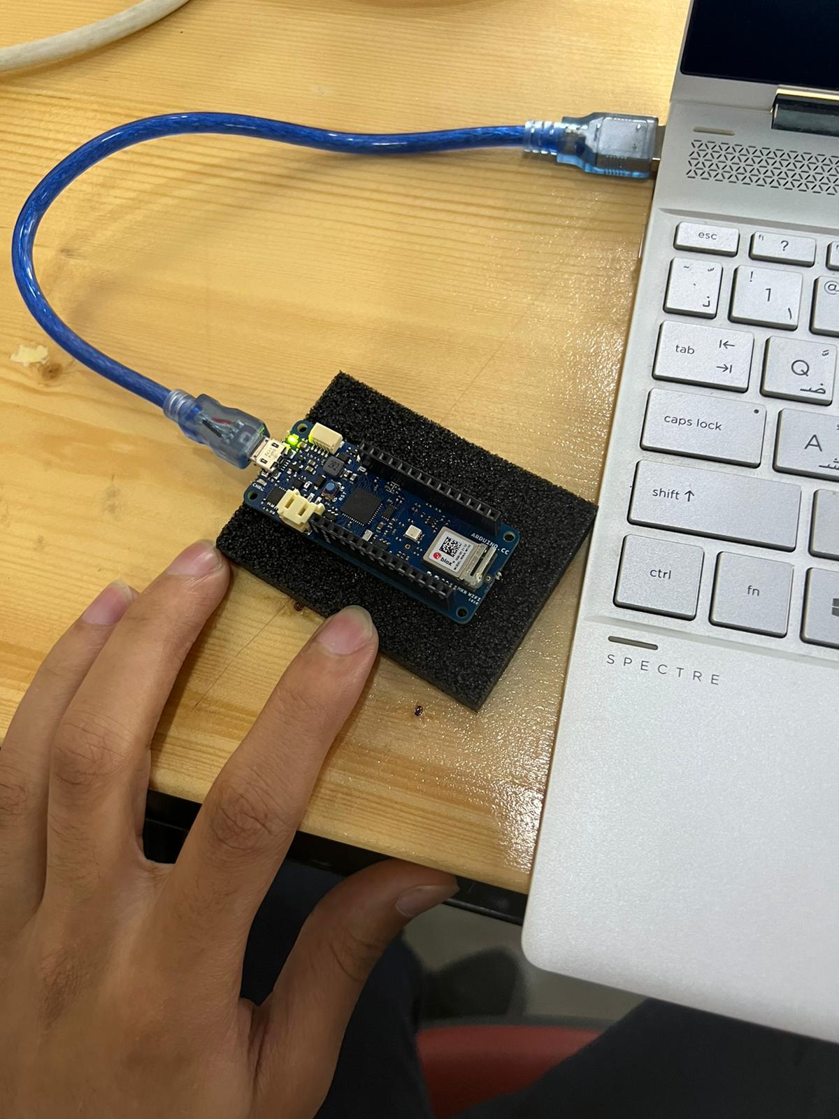
Tools/ Port and choose your microcontrollers
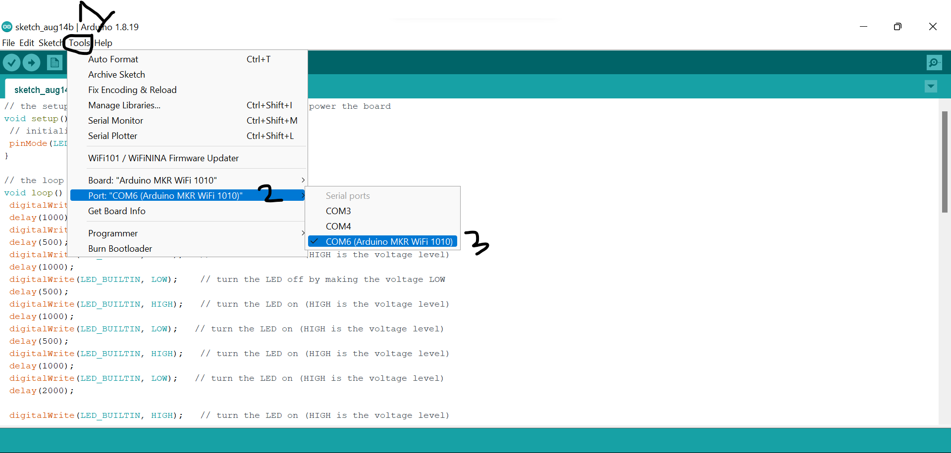
Click twice on it until green light is showing
And it is ready to be programmed :]
Blink
Simple programming code to make your microcontroller blink with the LED inserted on the board simple follow this:
Code Example of random blinking
/*
  Blink

  Turns an LED on for one second, then off for one second, repeatedly.

  Most Arduinos have an on-board LED you can control. On the UNO, MEGA and ZERO
  it is attached to digital pin 13, on MKR1000 on pin 6. LED_BUILTIN is set to
  the correct LED pin independent of which board is used.
  If you want to know what pin the on-board LED is connected to on your Arduino
  model, check the Technical Specs of your board at:
  https://www.arduino.cc/en/Main/Products

  modified 8 May 2014
  by Scott Fitzgerald
  modified 2 Sep 2016
  by Arturo Guadalupi
  modified 8 Sep 2016
  by Colby Newman

  This example code is in the public domain.

  https://www.arduino.cc/en/Tutorial/BuiltInExamples/Blink
*/

// the setup function runs once when you press reset or power the board
void setup() {
  // initialize digital pin LED_BUILTIN as an output.
  pinMode(LED_BUILTIN, OUTPUT);
}

// the loop function runs over and over again forever
void loop() {
  int A=random(500,5000);
  Serial.println(A);
  int B=random(500,5000);
  Serial.println(B);

  for(int j=0; j<10; j++){
    digitalWrite(LED_BUILTIN,HIGH);  // turn the LED on (HIGH is the voltage level)
    delay(A);                        // wait for a second
    digitalWrite(LED_BUILTIN,LOW);   // turn the LED off by making the voltage low
    delay(B);
  }                         // wait for a second

}
Morse Code
Morse code is a unique way to communicate were it language represented by combinations of long and short light or sound signals. It also can be written with dots, spaces and dashes you can use the following link to do so
We will apply this on our microcontroller to blink a word I chose the following word “Hello”
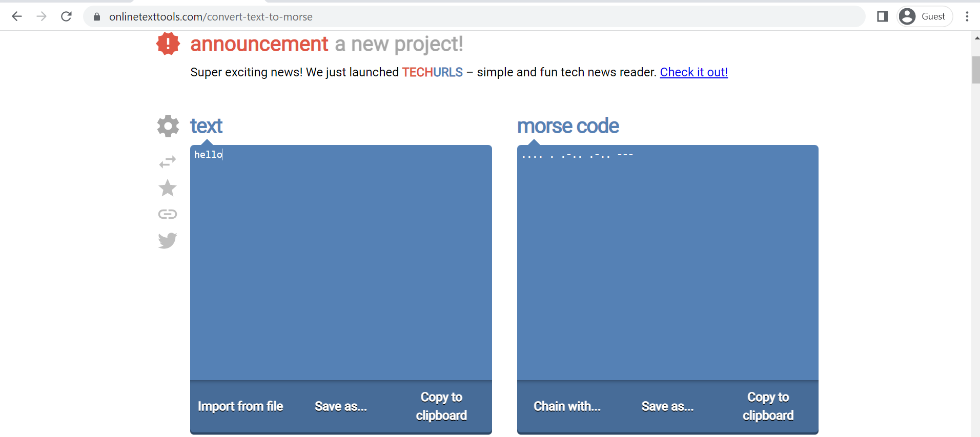
We will use the following rule to generate our code (.) = 1sec on (-) = 2sec on ( ) = 0.5sec off small space in same letter ( )= 2sec off space between two letters
Code Example of writing hello in morse code
// the setup function runs once when you press reset or power the board
void setup() {
 // initialize digital pin LED_BUILTIN as an output.
 pinMode(LED_BUILTIN, OUTPUT);
}

// the loop function runs over and over again forever
void loop() {
 digitalWrite(LED_BUILTIN, HIGH);   // turn the LED on (HIGH is the voltage level)
 delay(1000);                       // wait for a second
 digitalWrite(LED_BUILTIN, LOW);    // turn the LED off by making the voltage LOW
 delay(500);                       // wait for a second
 digitalWrite(LED_BUILTIN, HIGH);   // turn the LED on (HIGH is the voltage level)
 delay(1000);
 digitalWrite(LED_BUILTIN, LOW);    // turn the LED off by making the voltage LOW
 delay(500);
 digitalWrite(LED_BUILTIN, HIGH);   // turn the LED on (HIGH is the voltage level)
 delay(1000);
 digitalWrite(LED_BUILTIN, LOW);   // turn the LED on (HIGH is the voltage level)
 delay(500);
 digitalWrite(LED_BUILTIN, HIGH);   // turn the LED on (HIGH is the voltage level)
 delay(1000);
 digitalWrite(LED_BUILTIN, LOW);   // turn the LED on (HIGH is the voltage level)
 delay(2000);

 digitalWrite(LED_BUILTIN, HIGH);   // turn the LED on (HIGH is the voltage level)
 delay(1000);
 digitalWrite(LED_BUILTIN, LOW);   // turn the LED on (HIGH is the voltage level)
 delay(2000);

 digitalWrite(LED_BUILTIN, HIGH);   // turn the LED on (HIGH is the voltage level)
 delay(1000);
 digitalWrite(LED_BUILTIN, LOW);   // turn the LED on (HIGH is the voltage level)
 delay(500);
 digitalWrite(LED_BUILTIN, HIGH);   // turn the LED on (HIGH is the voltage level)
 delay(2000);
 digitalWrite(LED_BUILTIN, LOW);   // turn the LED on (HIGH is the voltage level)
 delay(500);
 digitalWrite(LED_BUILTIN, HIGH);   // turn the LED on (HIGH is the voltage level)
 delay(1000);
 digitalWrite(LED_BUILTIN, LOW);   // turn the LED on (HIGH is the voltage level)
 delay(500);
 digitalWrite(LED_BUILTIN, HIGH);   // turn the LED on (HIGH is the voltage level)
 delay(1000);
 digitalWrite(LED_BUILTIN, LOW);   // turn the LED on (HIGH is the voltage level)
 delay(2000);

   digitalWrite(LED_BUILTIN, HIGH);   // turn the LED on (HIGH is the voltage level)
 delay(1000);
 digitalWrite(LED_BUILTIN, LOW);   // turn the LED on (HIGH is the voltage level)
 delay(500);
 digitalWrite(LED_BUILTIN, HIGH);   // turn the LED on (HIGH is the voltage level)
 delay(2000);
 digitalWrite(LED_BUILTIN, LOW);   // turn the LED on (HIGH is the voltage level)
 delay(500);
 digitalWrite(LED_BUILTIN, HIGH);   // turn the LED on (HIGH is the voltage level)
 delay(1000);
 digitalWrite(LED_BUILTIN, LOW);   // turn the LED on (HIGH is the voltage level)
 delay(500);
 digitalWrite(LED_BUILTIN, HIGH);   // turn the LED on (HIGH is the voltage level)
 delay(1000);
 digitalWrite(LED_BUILTIN, LOW);   // turn the LED on (HIGH is the voltage level)
 delay(2000);


  digitalWrite(LED_BUILTIN, HIGH);   // turn the LED on (HIGH is the voltage level)
 delay(2000);
  digitalWrite(LED_BUILTIN, LOW);   // turn the LED on (HIGH is the voltage level)
 delay(500);
  digitalWrite(LED_BUILTIN, HIGH);   // turn the LED on (HIGH is the voltage level)
 delay(2000);
  digitalWrite(LED_BUILTIN, LOW);   // turn the LED on (HIGH is the voltage level)
 delay(500);
  digitalWrite(LED_BUILTIN, HIGH);   // turn the LED on (HIGH is the voltage level)
 delay(2000);
  digitalWrite(LED_BUILTIN, LOW);   // turn the LED on (HIGH is the voltage level)
 delay(500);
}
delay transfer
Code Example of transfering delay
  Blink

  Turns an LED on for one second, then off for one second, repeatedly.

  Most Arduinos have an on-board LED you can control. On the UNO, MEGA and ZERO
  it is attached to digital pin 13, on MKR1000 on pin 6. LED_BUILTIN is set to
  the correct LED pin independent of which board is used.
  If you want to know what pin the on-board LED is connected to on your Arduino
  model, check the Technical Specs of your board at:
  https://www.arduino.cc/en/Main/Products

  modified 8 May 2014
  by Scott Fitzgerald
  modified 2 Sep 2016
  by Arturo Guadalupi
  modified 8 Sep 2016
  by Colby Newman

  This example code is in the public domain.

  https://www.arduino.cc/en/Tutorial/BuiltInExamples/Blink
*/
int onBlinks=0;
int offBlinks=0;

// the setup function runs once when you press reset or power the board
void setup() {
  // initialize digital pin LED_BUILTIN as an output.
  pinMode(LED_BUILTIN, OUTPUT);
  digitalWrite(LED_BUILTIN,LOW);  // set the pin value on low at the begin
  Serial.begin(9600);
}

// the loop function runs over and over again forever
void loop() {
  while (onBlinks==0){
    Serial.println("How long do you want the LEDs to stay on in ms?");  // prompt user for input
    while (Serial.available() ==0){
      // wait for user to input data
    }
    onBlinks = Serial.parseInt();  // read the data the user has input
  }

  while (offBlinks==0){
    Serial.println("How long do you want the LEDs to stay off in ms?");  // prompt user for input
    while (Serial.available() ==1){
      // wait foe user to input data
    }
    offBlinks = Serial.parseInt();  // read the data the user has input
  }

  for(int i=0; i<5; i++){
    digitalWrite(LED_BUILTIN,HIGH);  // turn the LED on
    delay(onBlinks);  // wait for a second
    digitalWrite(LED_BUILTIN,LOW);   // turn the LED off
    delay(offBlinks);
    }
  }
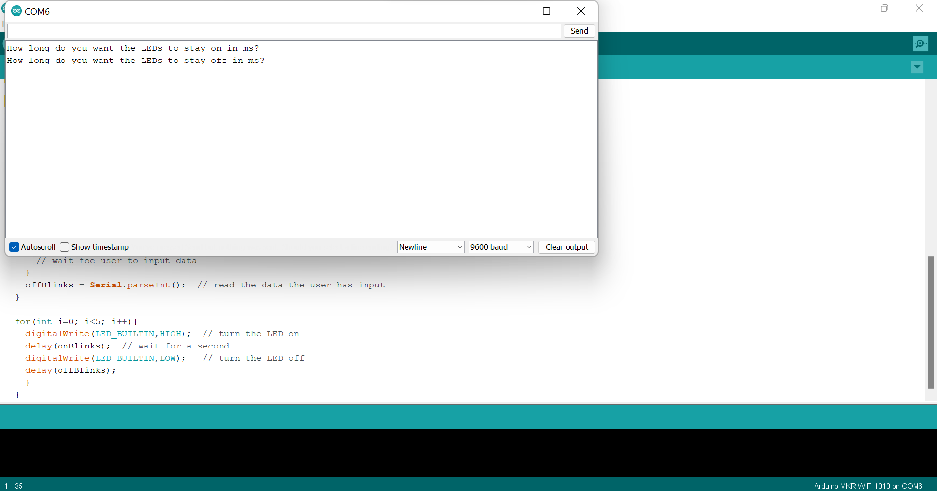
For LEDs to stay on i put 1000ms
For LEDs to stay off i put 2000ms
![]()
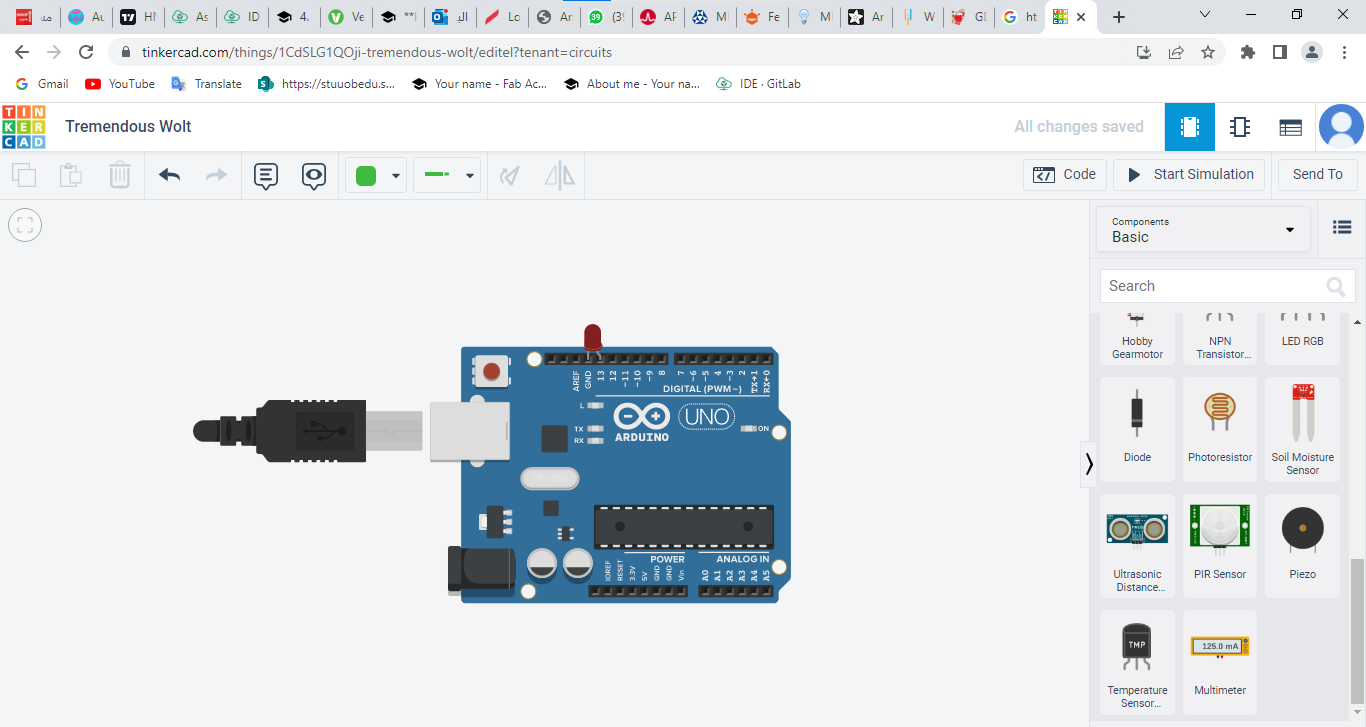
programing using tinkercad
Tinkercad also can be used to program like arduino IDE you need to choose electronics then the type of microelcontroller. if you are using MKR1010 you will not find it so use arduino because same coding is used
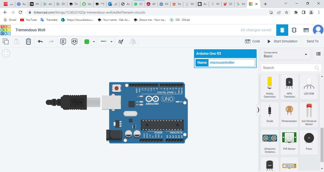
This site can make the code on the shape of blocks you can discover many function through it like repeat. I used it to make the same hello code
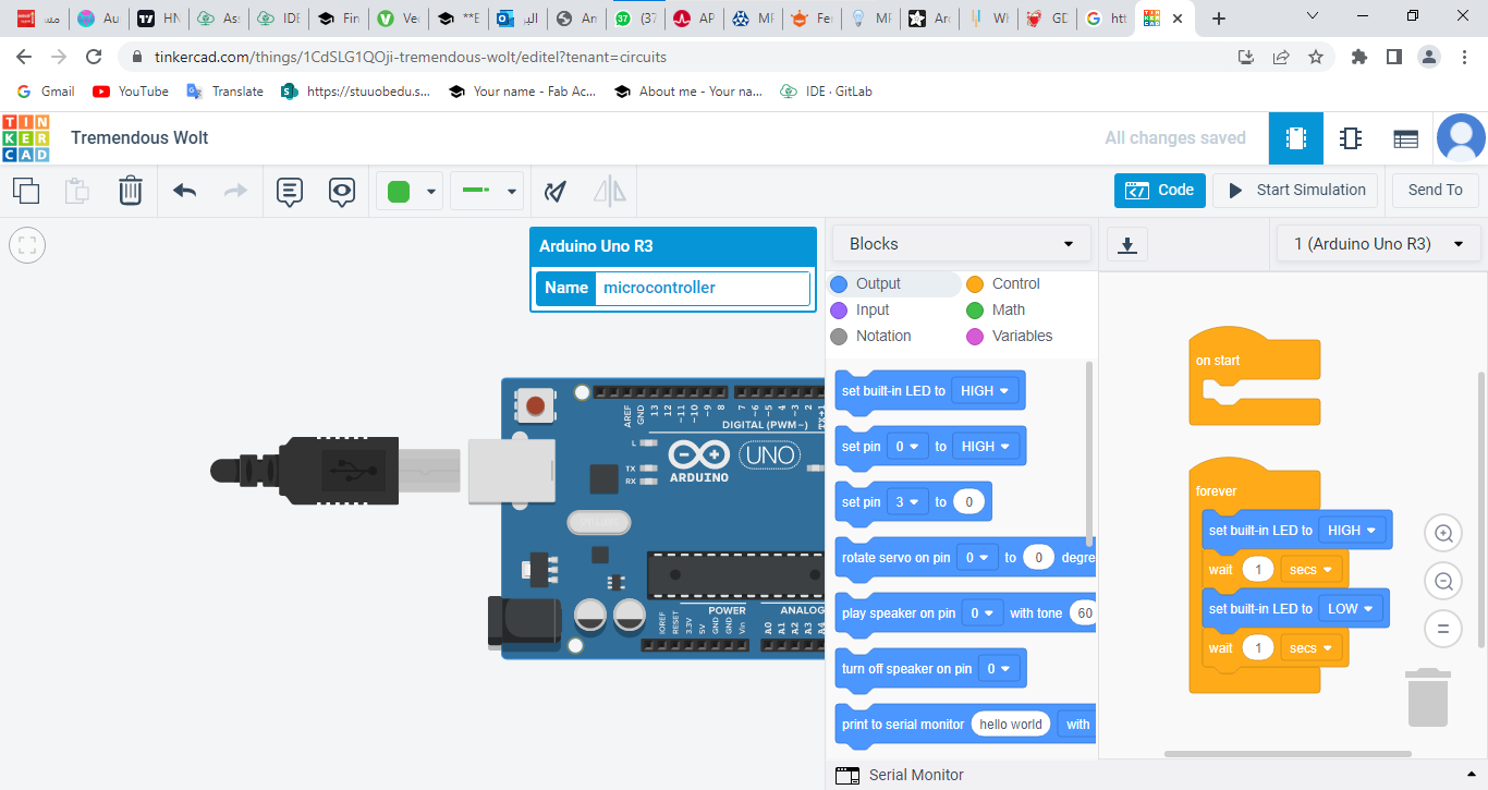
because I used repeat function the code is optimized with for inside the loop
 // C++ code
//
int counter;

int counter2;

int counter3;

int counter4;

int counter5;

void setup()
{
  pinMode(LED_BUILTIN, OUTPUT);
}

void loop()
{
  for (counter = 0; counter < 3; ++counter) {
    digitalWrite(LED_BUILTIN, HIGH);
    delay(1000); // Wait for 1000 millisecond(s)
    digitalWrite(LED_BUILTIN, LOW);
    delay(500); // Wait for 500 millisecond(s)
  }
  for (counter2 = 0; counter2 < 2; ++counter2) {
    digitalWrite(LED_BUILTIN, HIGH);
    delay(1000); // Wait for 1000 millisecond(s)
    digitalWrite(LED_BUILTIN, LOW);
    delay(2000); // Wait for 2000 millisecond(s)
  }
  for (counter3 = 0; counter3 < 2; ++counter3) {
    digitalWrite(LED_BUILTIN, HIGH);
  }
  for (counter4 = 0; counter4 < 2; ++counter4) {
    digitalWrite(LED_BUILTIN, HIGH);
    delay(2000); // Wait for 2000 millisecond(s)
    digitalWrite(LED_BUILTIN, LOW);
    delay(500); // Wait for 500 millisecond(s)
  }
  delay(1000); // Wait for 1000 millisecond(s)
  digitalWrite(LED_BUILTIN, LOW);
  delay(500); // Wait for 500 millisecond(s)
  digitalWrite(LED_BUILTIN, HIGH);
  delay(2000); // Wait for 2000 millisecond(s)
  for (counter5 = 0; counter5 < 2; ++counter5) {
    digitalWrite(LED_BUILTIN, LOW);
    delay(500); // Wait for 500 millisecond(s)
    digitalWrite(LED_BUILTIN, HIGH);
    delay(1000); // Wait for 1000 millisecond(s)
  }
  digitalWrite(LED_BUILTIN, HIGH);
  delay(2000); // Wait for 2000 millisecond(s)
}
Tinkercad also allows simulation to any object external like LED to be connected to the Arduino through pin no 13