7. Input & Output device
This week I worked on different elements that is either output or input devices including how to program them & connections
Types of wires
1-Positive: Voltage common collector (vcc) or vin
2-Negative: Ground or GND
Different Aspects
1-Microcontroller: can be used as power source
2-Digital: alternating voltage between high & low
3-Analog: Can have many voltage due to the sinusoidal pattern. In other words you can control voltage amount using it
4-Currents: We have two types of currents AC & DC
Input Sensors
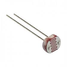
1-Light Sensor It works on the photoresistor light sensitivity and resistance to the amount of light falling on it
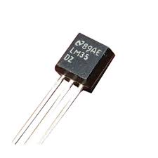
2-Temperature Sensor Device used to measure temperature depending on its resistance & the received voltage
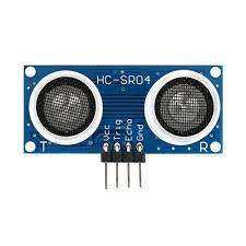
3-Ultrasonic Sensor It is distance sensor it measures the distance by emitting high frequency sound waves and receiving the reflection back. The time it takes to go & rebound is calculated and converted to distance
for me i choose the LDR sensor as input sensor
LDR sensor with MKR1010 microcontroller
LDR sensor which refer to Light Dependent Resistor (Photoresistor)
how does LDR sensor works
It is relatively easy to understand the basics of how an LDR works without delving into complicated explanations. It is first necessary to understand that an electrical current consists of the movement of electrons within a material.
Good conductors have a large number of free electrons that can drift in a given direction under the action of a potential difference. Insulators with a high resistance have very few free electrons, and therefore it is hard to make the them move and hence a current to flow.
An LDR or photoresistor is made any semiconductor material with a high resistance. It has a high resistance because there are very few electrons that are free and able to move - the vast majority of the electrons are locked into the crystal lattice and unable to move. Therefore in this state there is a high LDR resistance.
As light falls on the semiconductor, the light photons are absorbed by the semiconductor lattice and some of their energy is transferred to the electrons.
The amount of energy transferred to the electrons gives some of them sufficient energy to break free from the crystal lattice so that they can then conduct electricity. This results in a lowering of the resistance of the semiconductor and hence the overall LDR resistance.
the process is progressive, and as more light shines on the LDR semiconductor, so more electrons are released to conduct electricity and the resistance falls further
connection of the sensor
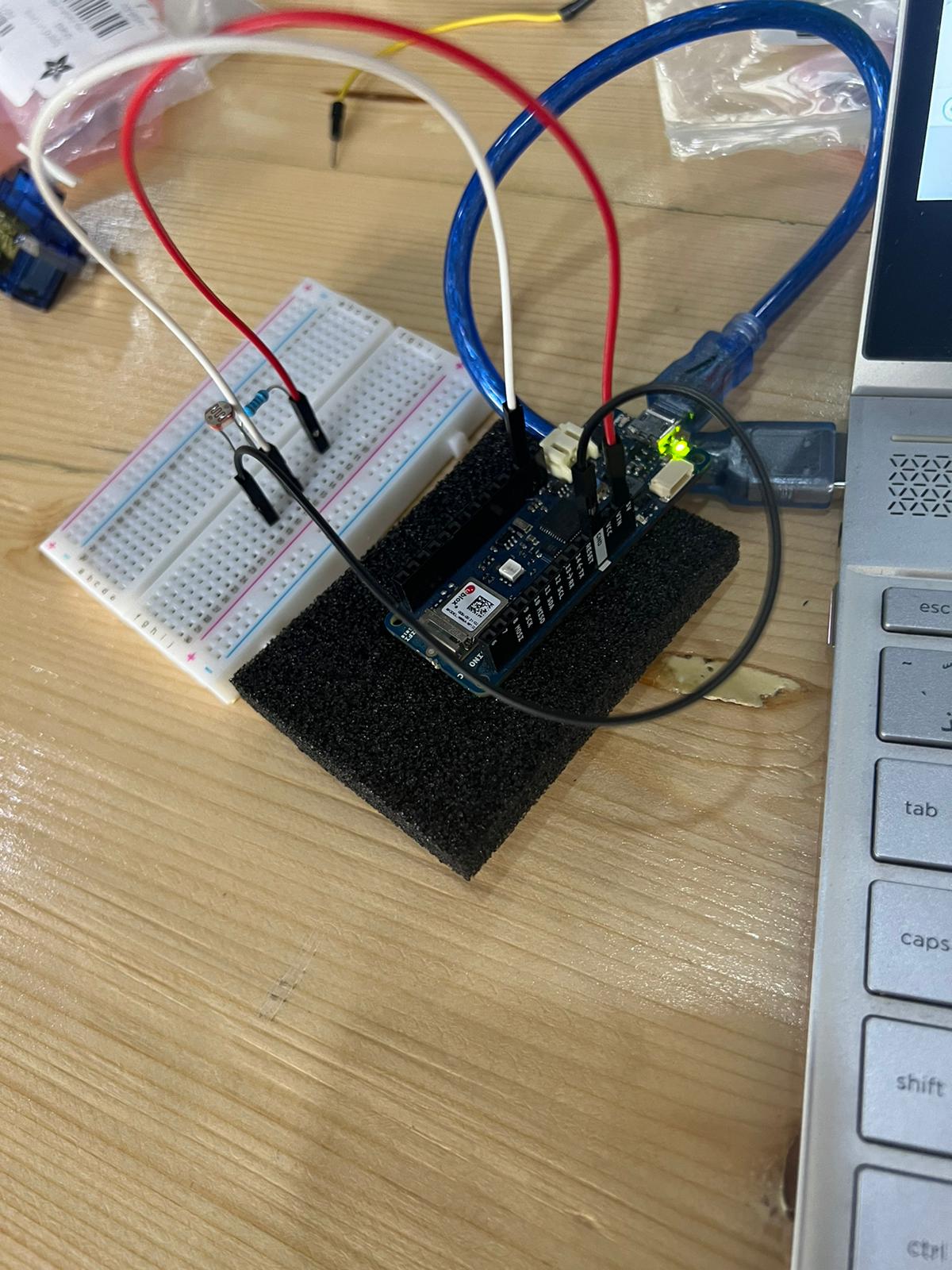
the code of the LDR sensor with volt unit
/*
  ReadAnalogVoltage

  Reads an analog input on pin 0, converts it to voltage, and prints the result to the Serial Monitor.
  Graphical representation is available using Serial Plotter (Tools > Serial Plotter menu).
  Attach the center pin of a potentiometer to pin A0, and the outside pins to +5V and ground.

  This example code is in the public domain.

  https://www.arduino.cc/en/Tutorial/BuiltInExamples/ReadAnalogVoltage
*/

// the setup routine runs once when you press reset:
void setup() {
  // initialize serial communication at 9600 bits per second:
  Serial.begin(9600);
}

// the loop routine runs over and over again forever:
void loop() {
  // read the input on analog pin 0:
  int sensorValue = analogRead(A0);
  // Convert the analog reading (which goes from 0 - 1023) to a voltage (0 - 5V):
  float voltage = sensorValue * (5.0 / 1023.0);
  // print out the value you read:
  Serial.println(voltage);
}
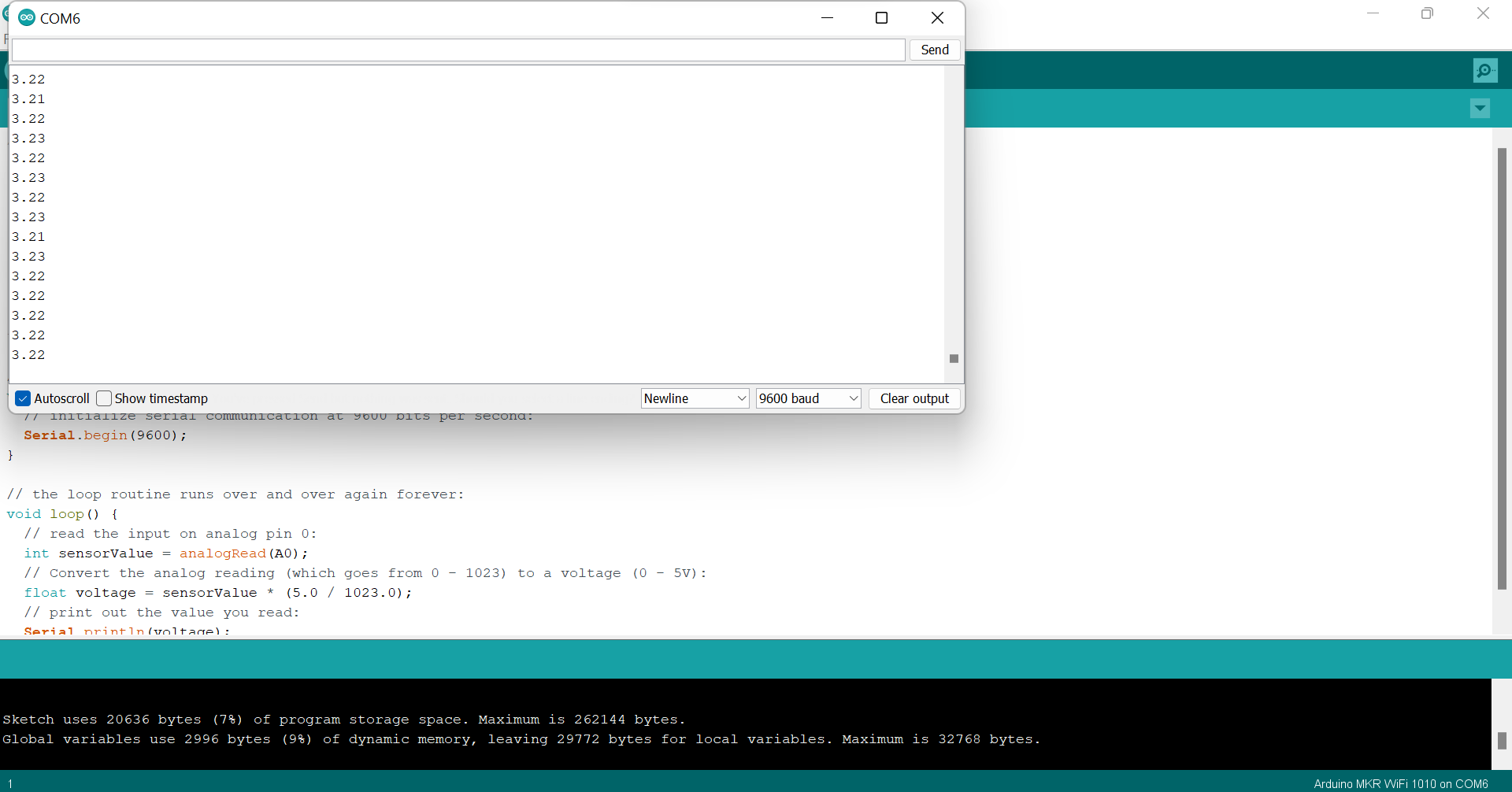
result of test for three cases
case1: when i dont put any thing around the LDR (on the status of the room)
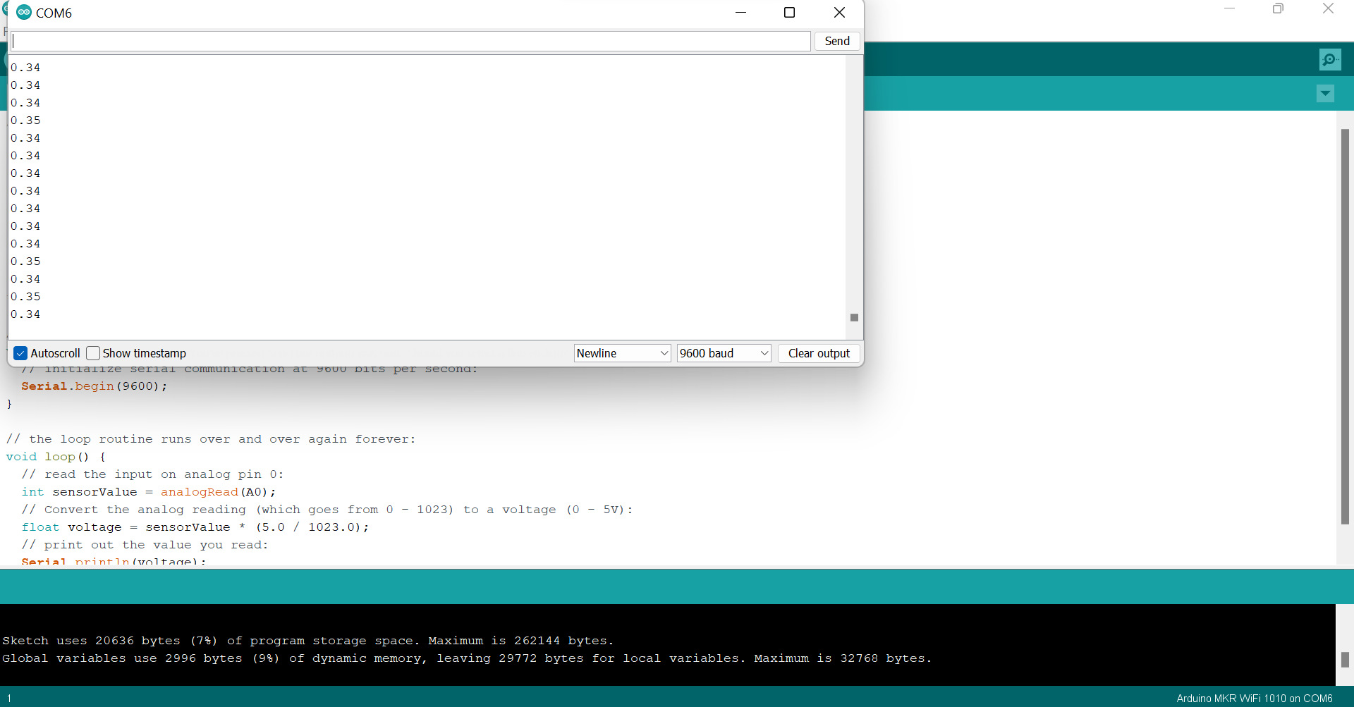
case2: when i put my hand around the LDR (covering the LDR with my hand)
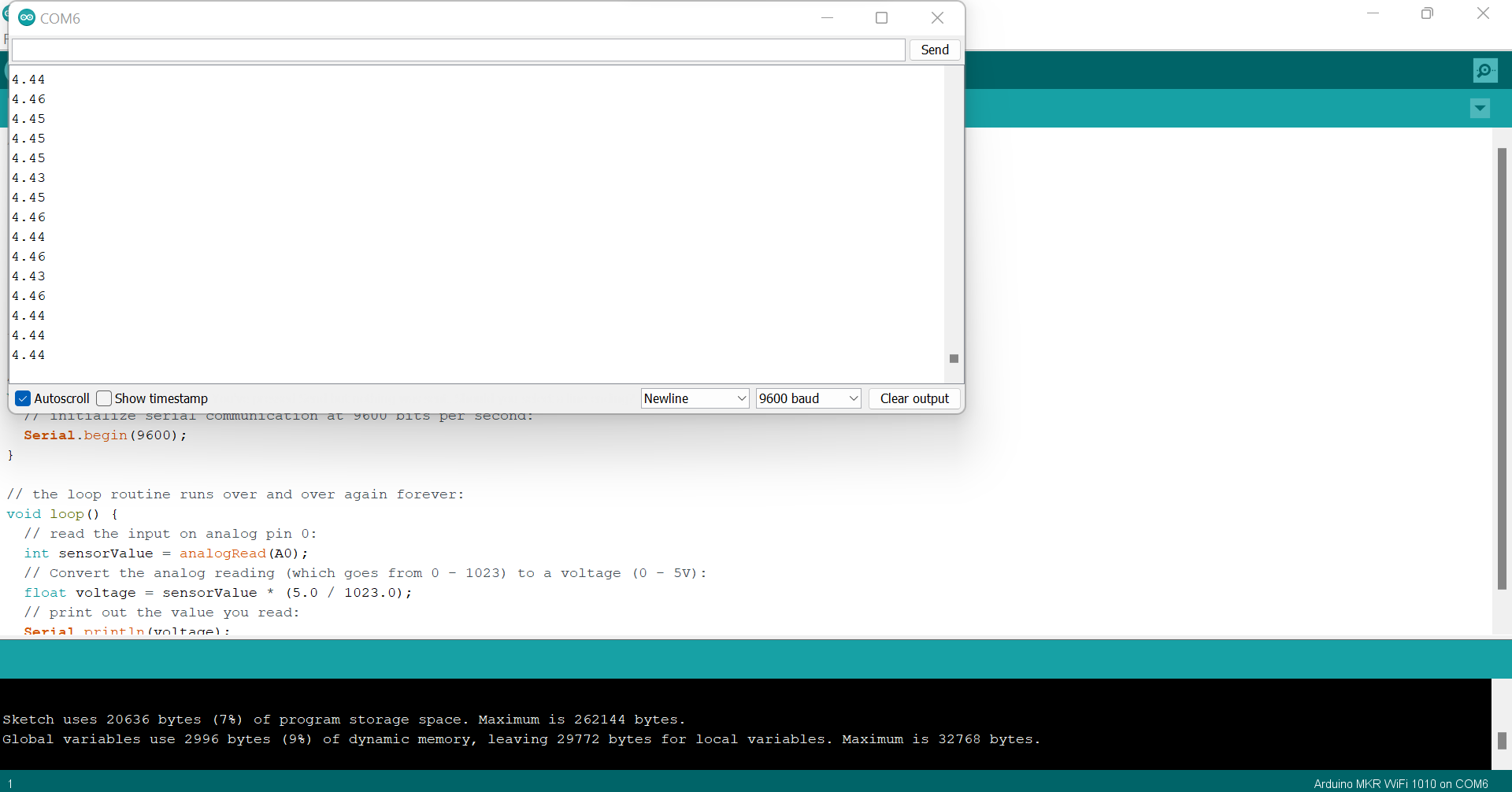
case3: when i put the light of the phone around the LDR
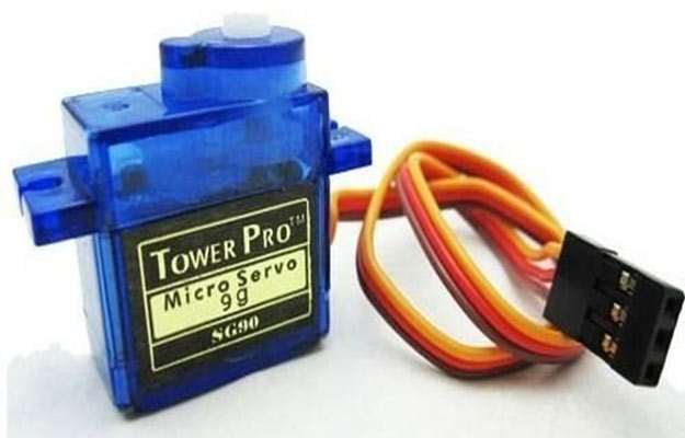
output sensor
for output sensor we use the servo motor
connection of servo motor with mkr1010
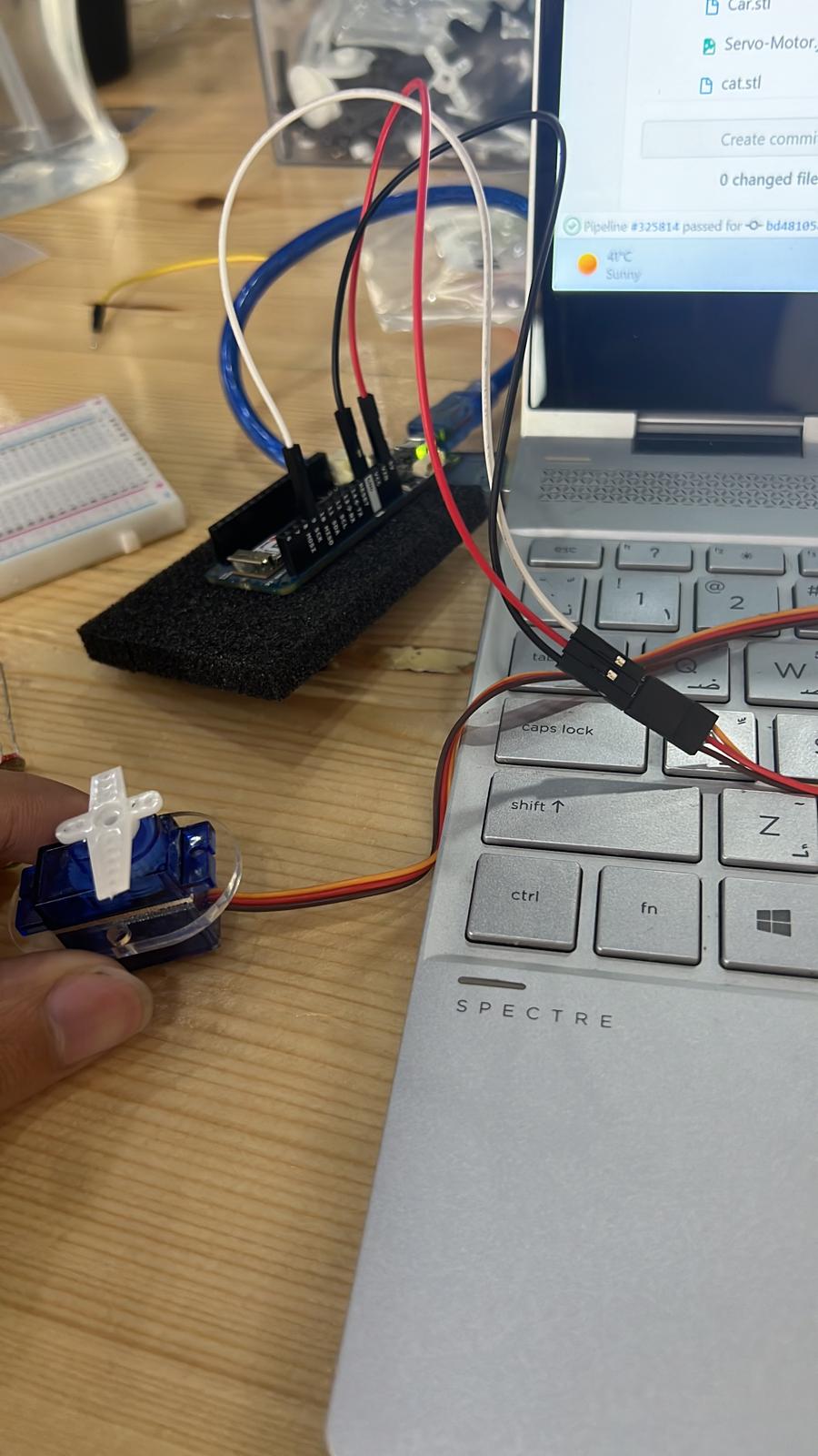
the code of servo motor
/* Servo motor with Arduino example code. Position and sweep. More info: https://www.makerguides.com/ */

// Include the servo library:
#include <Servo.h>

// Create a new servo object:
Servo myservo;

// Define the servo pin:
#define servoPin 9

// Create a variable to store the servo position:
int angle = 0;

void setup() {
  // Attach the Servo variable to a pin:
  myservo.attach(servoPin);
}

void loop() {
  // Tell the servo to go to a particular angle:
  myservo.write(90);
  delay(1000);
  myservo.write(180);
  delay(1000);
  myservo.write(0);
  delay(1000);

  // Sweep from 0 to 180 degrees:
  for (angle = 0; angle <= 180; angle += 1) {
    myservo.write(angle);
    delay(15);
  }

  // And back from 180 to 0 degrees:
  for (angle = 180; angle >= 0; angle -= 1) {
    myservo.write(angle);
    delay(30);
  }
  delay(1000);
}
the result of output(the servo motor)
the result is the motor rotating in 180 degree only
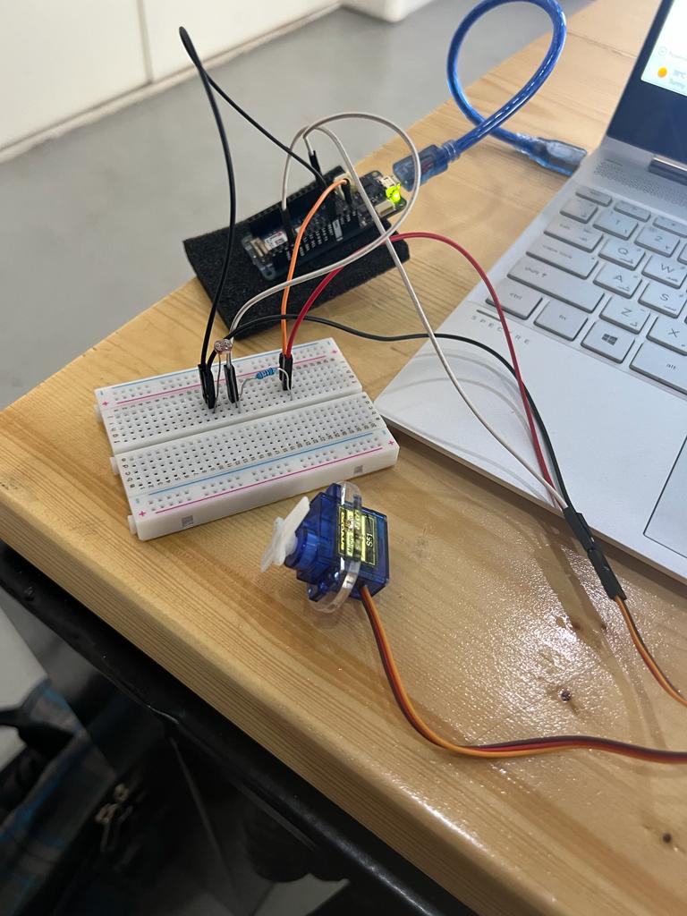
full system(input&output together), the input(LDR sensor) with the output(servo motor)
for the full system i choose for input the (LDR sensor) and for the output i choose the (servo motor)
connection of LDR sensor & SERVO motor with mkr1010
the code of LDR sensor & SERVO motor together
#include <Servo.h>

Servo myservo;  // create servo object to control a servo
int ldr = 0;  //analog pin to which LDR is connected
int ldr_value = 0; //variable to store LDR values
int take_photo = 100; // value when we want to take a photo when a light comes on
int pos = 0;    // variable to store the servo position


void setup() {
Serial.begin(9600); //start serial Monitor
myservo.attach(9);  // attaches the servo on pin 9 to the servo object
}

void loop() {

ldr_value = analogRead(ldr);
Serial.println(ldr_value); //prints photoresistor value
delay(100); // value updated every 0.1 second.

if (ldr_value < take_photo) // if sensor value is less than 100 it will turn the servo on.
   {
    //take photo

    for (pos = 0; pos <= 180; pos += 1) { // goes from 0 degrees to 180 degrees
        // in steps of 1 degree
        myservo.write(pos);              // tell servo to go to position in variable 'pos'
        delay(5);                       // waits 5ms for the servo to reach the position
      }
      for (pos = 180; pos >= 0; pos -= 1) { // goes from 180 degrees to 0 degrees
        myservo.write(pos);              // tell servo to go to position in variable 'pos'
        delay(5);                       // waits 5ms for the servo to reach the position
      }
      delay (10000);  //wait 10 seconds before checking again

    }
   else
   {
    Serial.println(ldr_value);
   }
}
the result of input and output together
i didint face any issue during this week
group assignment
for group assignment check out sami’s documentation