4. Embedded programming
This week i worked on software called Arduino which is open-source Arduino Software (IDE) makes it easy to write code and upload it to the board. This software can be used with any Arduino board.
What is Miscroconroller?
A microcontroller is a compact integrated circuit designed to govern a specific operation in an embedded system. A typical microcontroller includes a processor, memory and input/output (I/O) peripherals on a single chip.
Sometimes referred to as an embedded controller or microcontroller unit (MCU), microcontrollers are found in vehicles, robots, office machines, medical devices, mobile radio transceivers, vending machines and home appliances, among other devices. They are essentially simple miniature personal computers (PCs) designed to control small features of a larger component, without a complex front-end operating system (OS).
How does it work ?
A microcontroller is embedded inside of a system to control a singular function in a device. It does this by interpreting data it receives from its I/O peripherals using its central processor. The temporary information that the microcontroller receives is stored in its data memory, where the processor accesses it and uses instructions stored in its program memory to decipher and apply the incoming data. It then uses its I/O peripherals to communicate and enact the appropriate action.
Microcontrollers are used in a wide array of systems and devices. Devices often utilize multiple microcontrollers that work together within the device to handle their respective tasks.
For example, a car might have many microcontrollers that control various individual systems within, such as the anti-lock braking system, traction control, fuel injection or suspension control. All the microcontrollers communicate with each other to inform the correct actions. Some might communicate with a more complex central computer within the car, and others might only communicate with other microcontrollers. They send and receive data using their I/O peripherals and process that data to perform their designated tasks.
Arduino -introduction and setup
First:I opened the board manager from tools>board>board manager and search by writing the board name
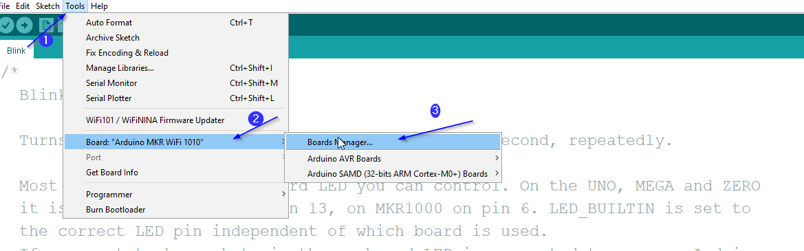
Second:From board manager, i searched for the model i worked on which is “mkr 1010 wifi ” and installed it so i could start working on it

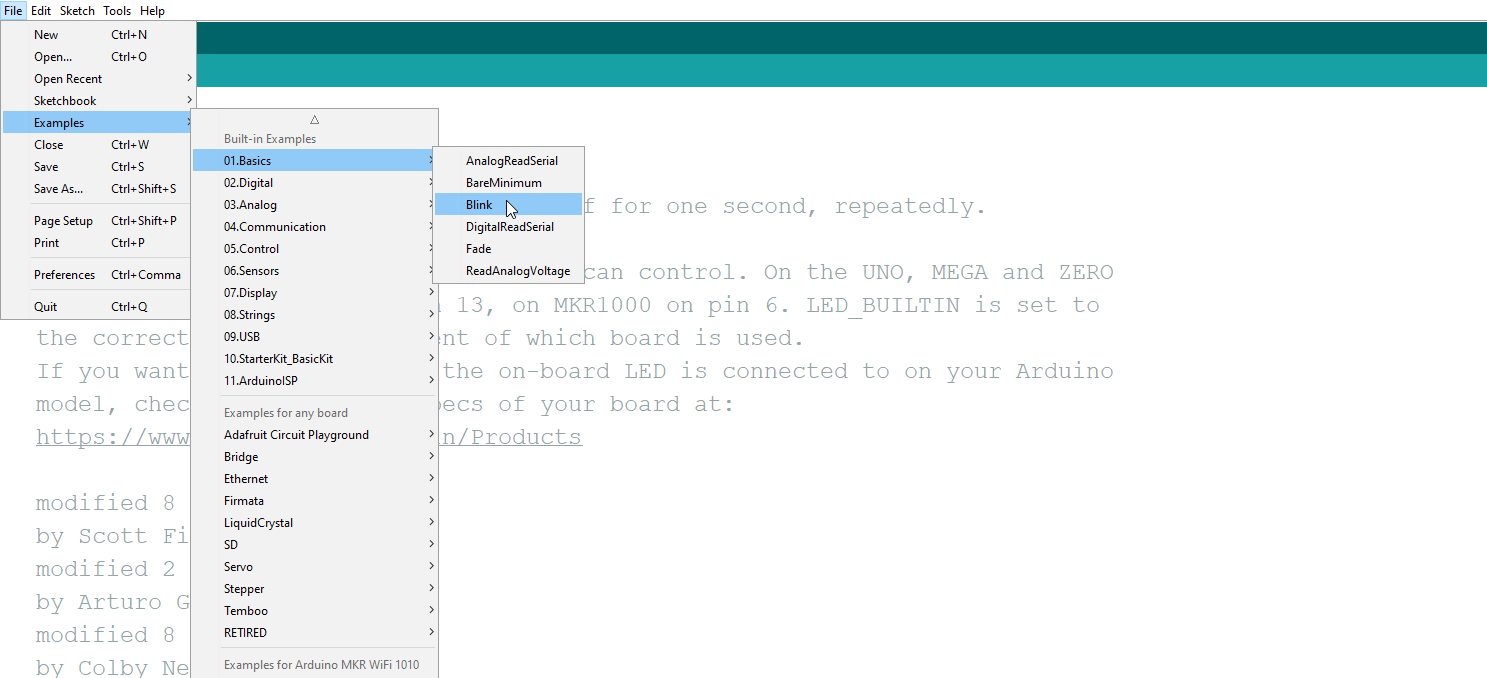
Third:i worked on assesment using “Blink” saved in arduino
Arduino - Assessments
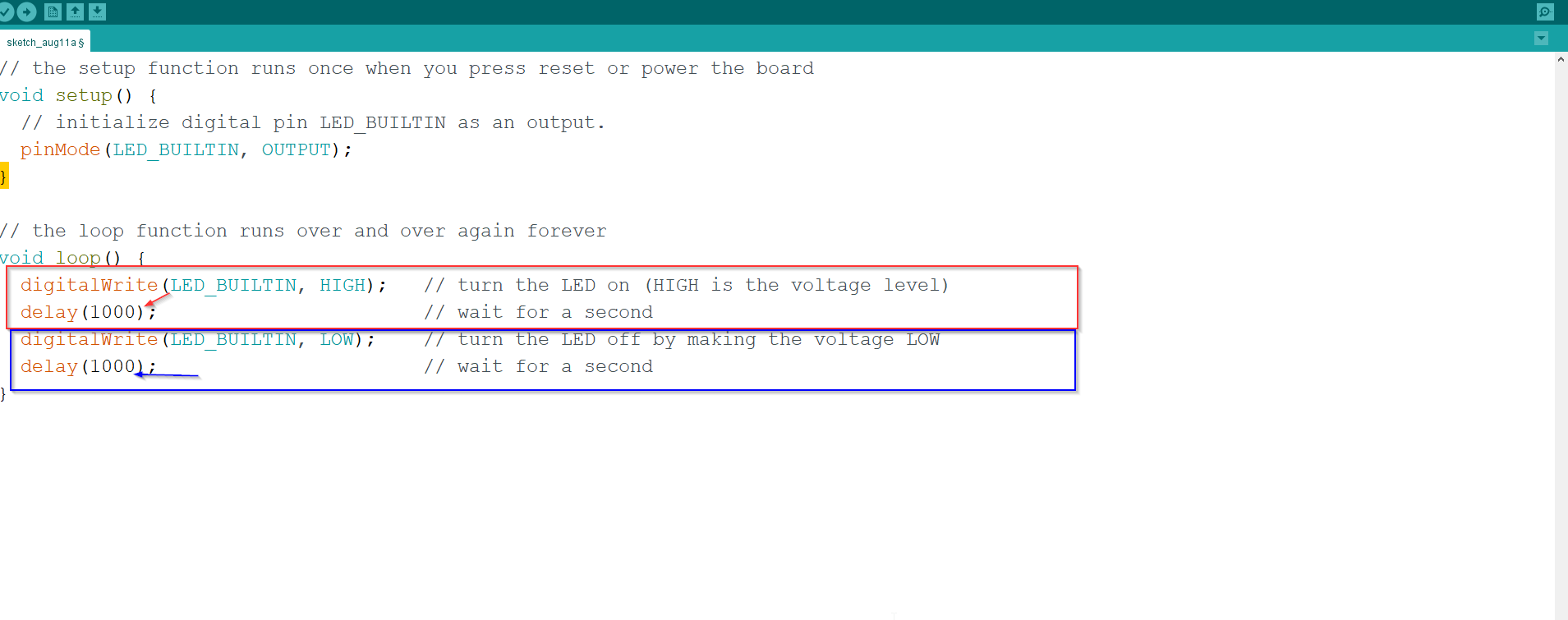
Assesment(1):in this assesment, i was required to do a simple morse code
Here in the red tringular, is command to make the board Turns on for a time that is specfided in the next line,the time is in milli second.
As for blue tringular, is commange to make board Turns offf for a time that is specified in the next line
void setup() {

  // initialize digital pin LED_BUILTIN as an output.
  pinMode(LED_BUILTIN, OUTPUT);
}

// the loop function runs over and over again forever
void loop() {
digitalWrite(LED_BUILTIN, HIGH);
delay(1000);
digitalWrite(LED_BUILTIN, LOW);
delay(1000);
     }
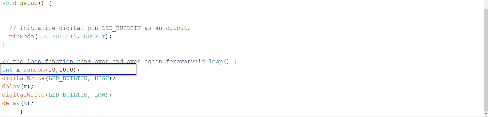
Assesment(2):in this assesment, i was required to do the same as Assesment(1) but with random delay
it was basically the same as assesment(1) but instead , i defined integer called random which will generate a random number in the range specfied , and then the timing of the on and off time will be that random number
void setup() {

  // initialize digital pin LED_BUILTIN as an output.
  pinMode(LED_BUILTIN, OUTPUT);
}

// the loop function runs over and over again forever
void loop() {
int x=random(10,1000);
digitalWrite(LED_BUILTIN, HIGH);
delay(x);
digitalWrite(LED_BUILTIN, LOW);
delay(x);
     }
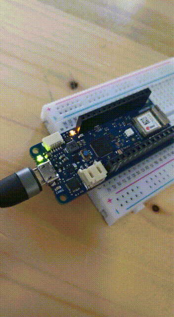
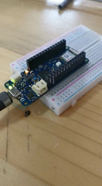
Hero shot video
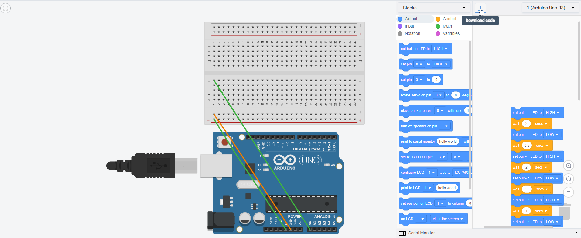
Programming using tinkercad
STEP1:open tinkercad and click on design
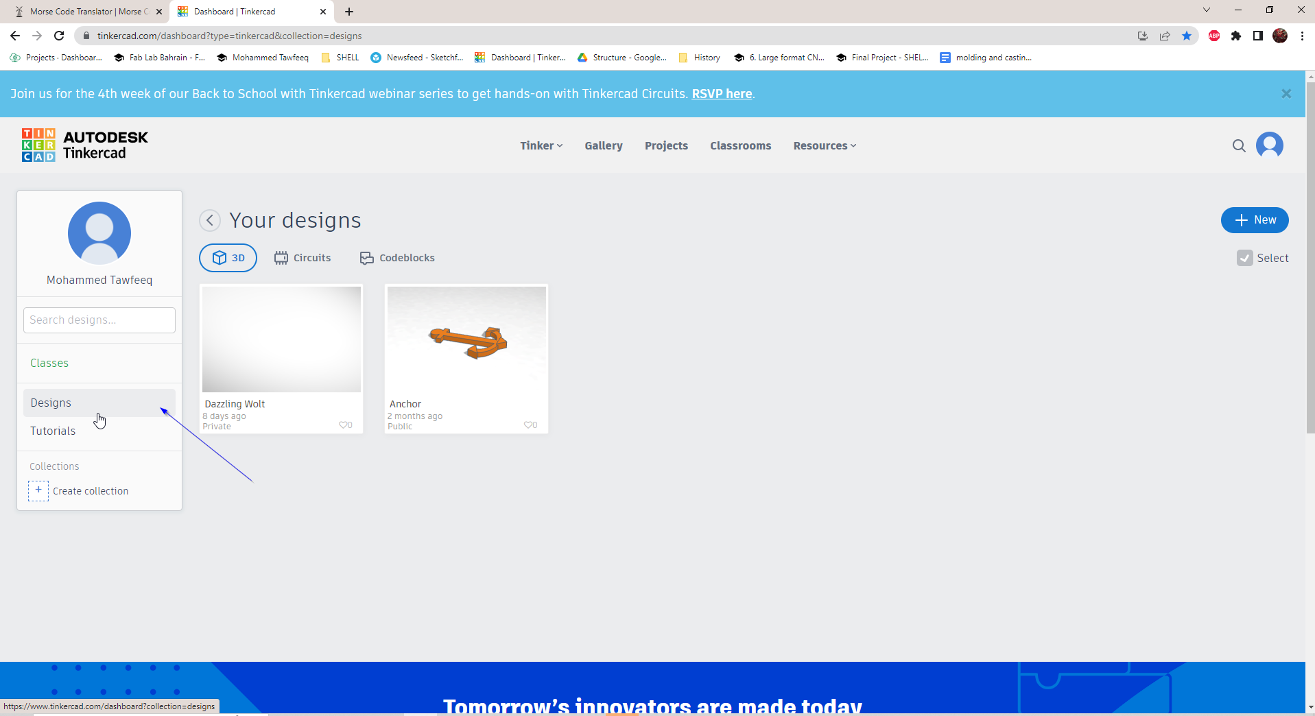
STEP2:Click New > circuit

STEP3:Here i added the blockes to write the word “map” in morse code
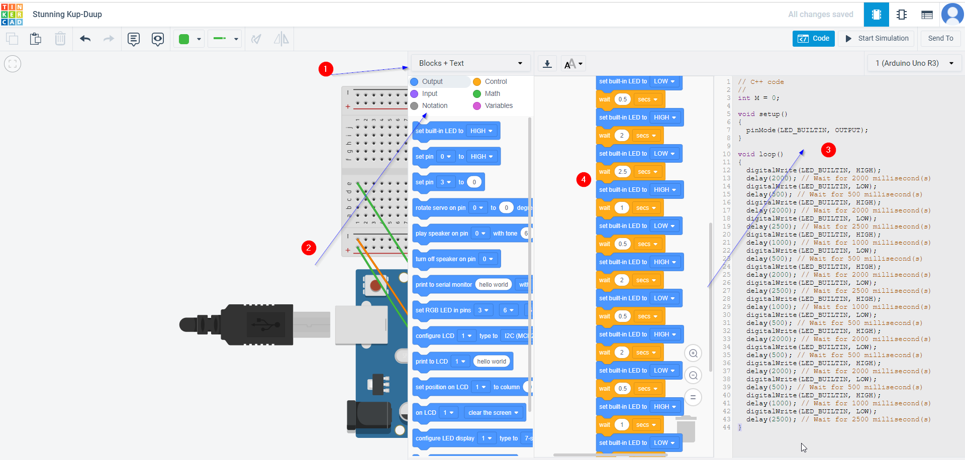
STEP:Finally i downloaded the code and it is downloaded as ino file that can be run using IDE
Code:
int M = 0;

void setup()
{
  pinMode(LED_BUILTIN, OUTPUT);
}

void loop()
{
  digitalWrite(LED_BUILTIN, HIGH);
  delay(2000); // Wait for 2000 millisecond(s)
  digitalWrite(LED_BUILTIN, LOW);
  delay(500); // Wait for 500 millisecond(s)
  digitalWrite(LED_BUILTIN, HIGH);
  delay(2000); // Wait for 2000 millisecond(s)
  digitalWrite(LED_BUILTIN, LOW);
  delay(2500); // Wait for 2500 millisecond(s)
  digitalWrite(LED_BUILTIN, HIGH);
  delay(1000); // Wait for 1000 millisecond(s)
  digitalWrite(LED_BUILTIN, LOW);
  delay(500); // Wait for 500 millisecond(s)
  digitalWrite(LED_BUILTIN, HIGH);
  delay(2000); // Wait for 2000 millisecond(s)
  digitalWrite(LED_BUILTIN, LOW);
  delay(500); // Wait for 500 millisecond(s)
  digitalWrite(LED_BUILTIN, HIGH);
  delay(2000); // Wait for 2000 millisecond(s)
  digitalWrite(LED_BUILTIN, LOW);
  delay(500); // Wait for 500 millisecond(s)
  digitalWrite(LED_BUILTIN, HIGH);
  delay(1000); // Wait for 1000 millisecond(s)
  digitalWrite(LED_BUILTIN, LOW);
  delay(2500); // Wait for 2500 millisecond(s)
}
HERO SHOT VIDEO 2