4. Embedded Programming
Introduction
This week we were introduced to embedded programming and specifically the microcontroller board. So, What is the microcontroller?
“It is a compact integrated circuit designed to govern a specific operation in an embedded system. A typical microcontroller includes a processor, memory, and input/output (I/O) peripherals on a single chip.”
Group Assignment
For the group assignment, each group was given a different type of microcontroller and asked to search and identify certain characteristics.
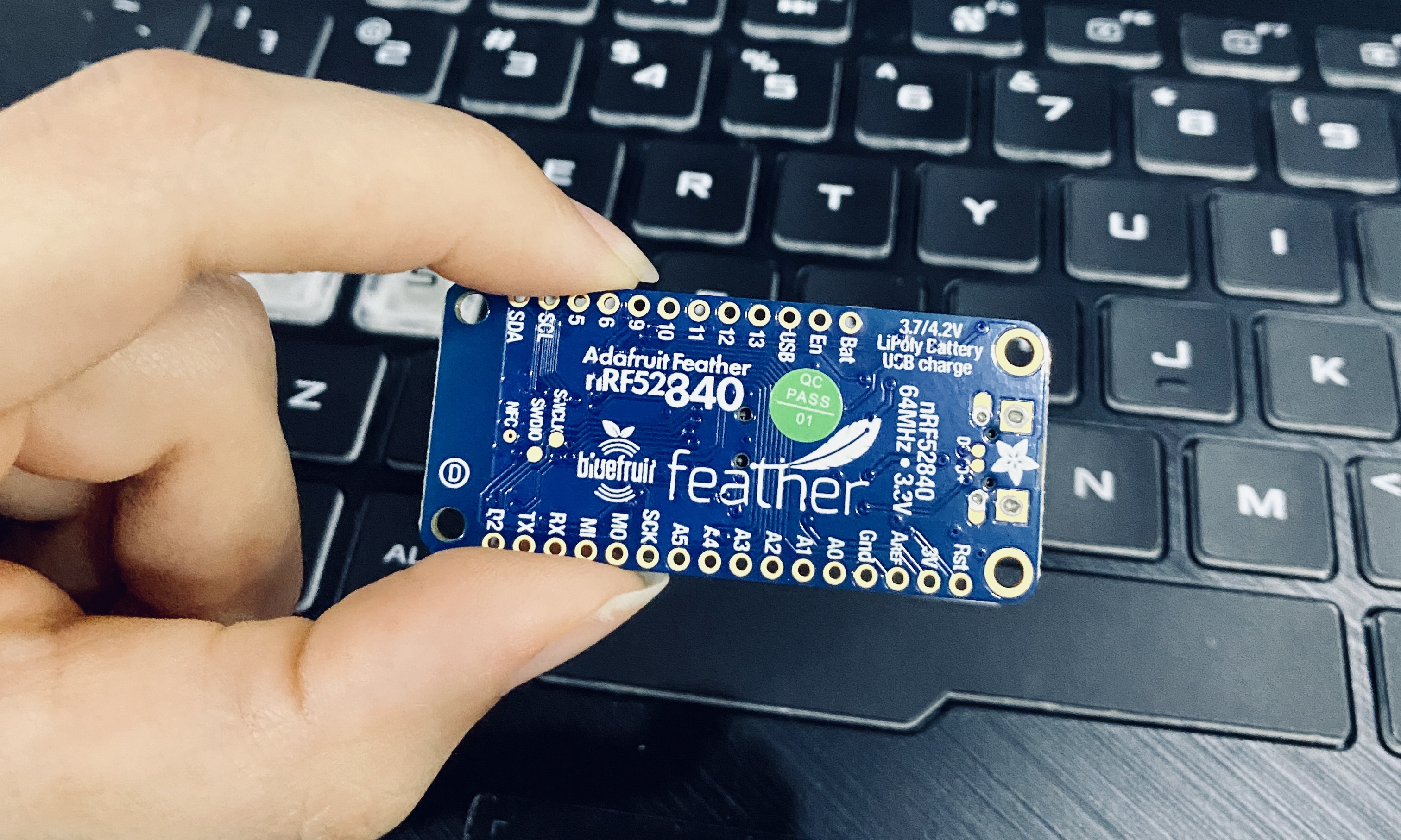
Our group (Sara, Noor, and I) had this microcontroller shown below.
-
Name and Type of the Microcontroller: Adafruit Feather nRF52840 Express
-
Number of Pins: 28 pins
-
Types of Pins: GPIO, ADC pins, PWM outputs
-
Types of Sensors: None, but can connect external sensors
-
Types of Languages that can be programmed with: Python, C++
Click here to see the entire group assignment where we compared all the different types of the microcontrollers.
Individual Assignment
Arduino IDE
For the individual assignment, we started by downloading “Arduino IDE” software as it is an open-source that makes it easy to write code and upload it to the board.
How to download the software?
- Visit the Arduino website
- Choose the suitable download option for your PC
- Click on “Just Download” and it will start downloading automatically
After downloading “Arduino IDE” software, we followed the steps on Adafruit website in order to set it up to the Adafruit Feather nRF52840 Express microcontroller.
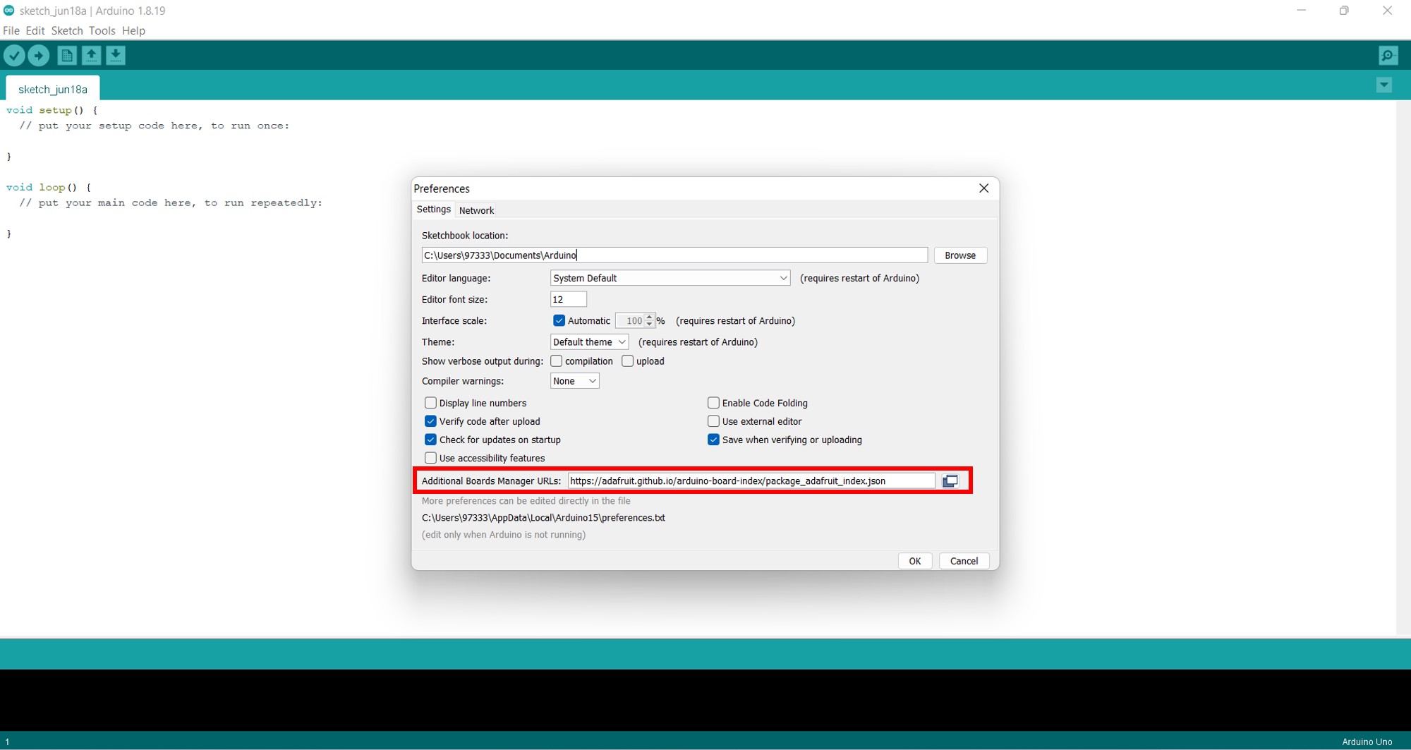
So first of all, I started the Arduino IDE, went into Preferences, and added “https://adafruit.github.io/arduino-board-index/package_adafruit_index.json” as an ‘Additional Board Manager URL’ as shown in the image below.
After that, I restarted the Arduino IDE, opened the ‘Boards Manager’ option from the Tools -> Board menu, and installed ‘Adafruit nRF52 by Adafruit’ as shown in the following image.
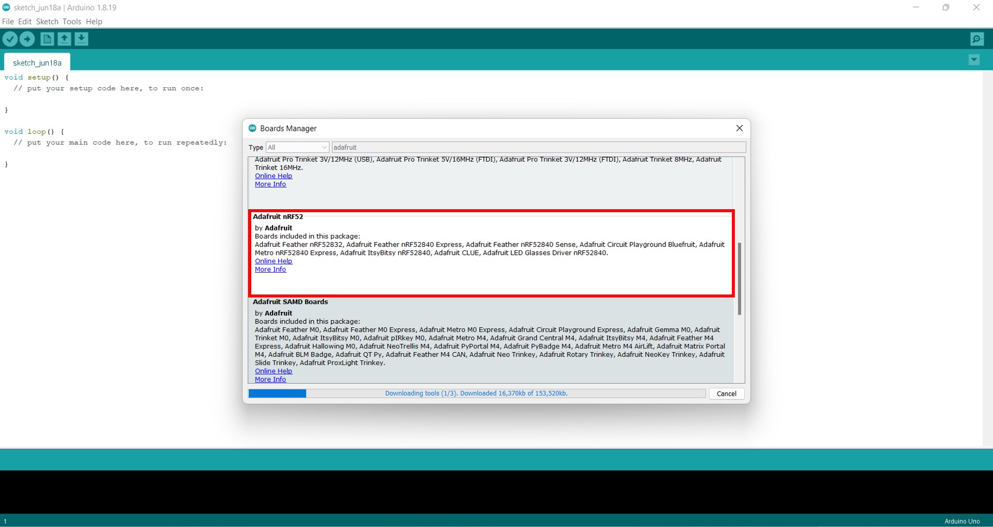
Note: The delay during the installation stage is normal, so be patient and let it terminate normally.
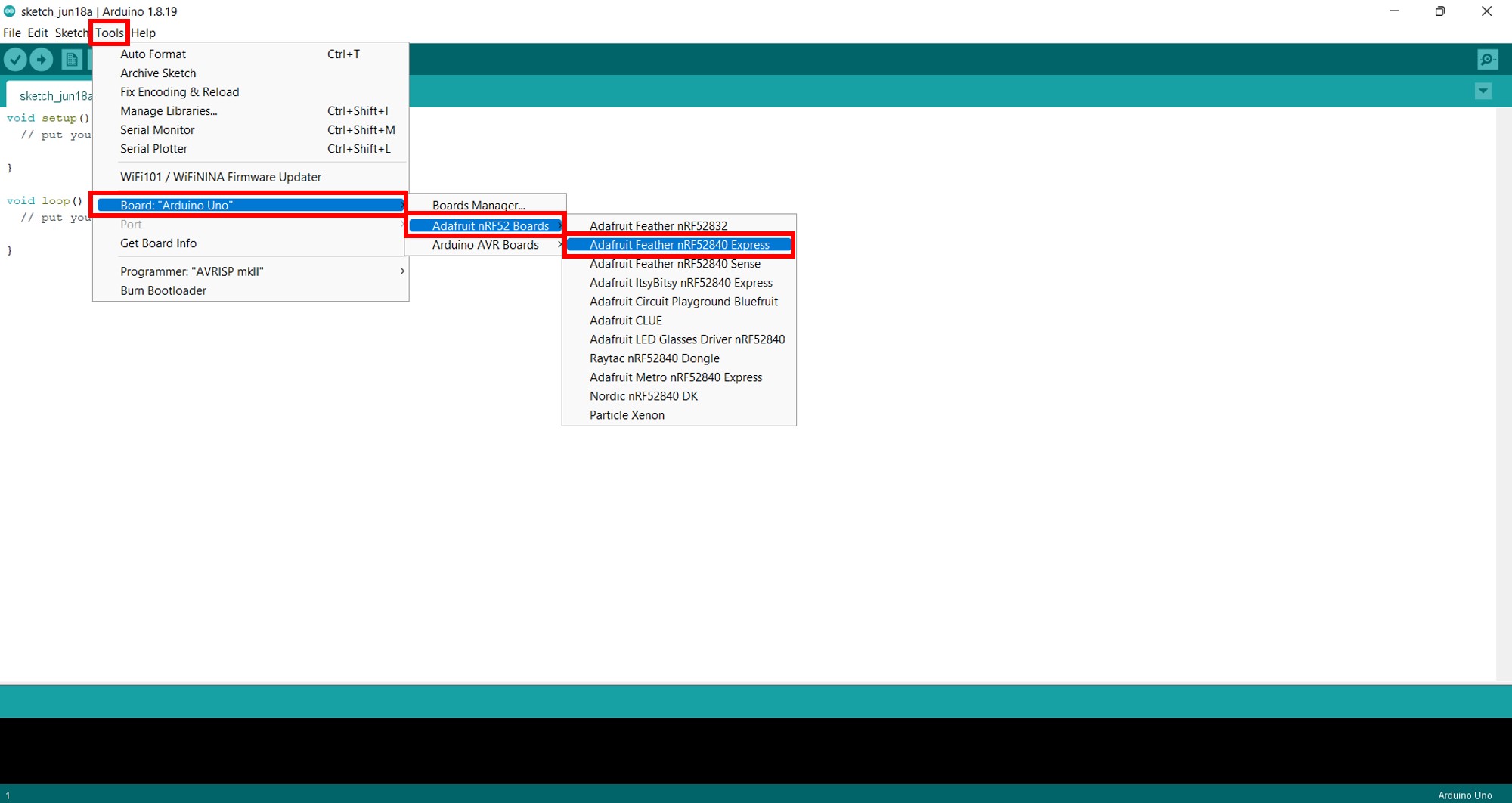
Once it is installed, config to use the right compiler and settings from the ‘Tools –> Board’ menu as shown here.
Blink Code
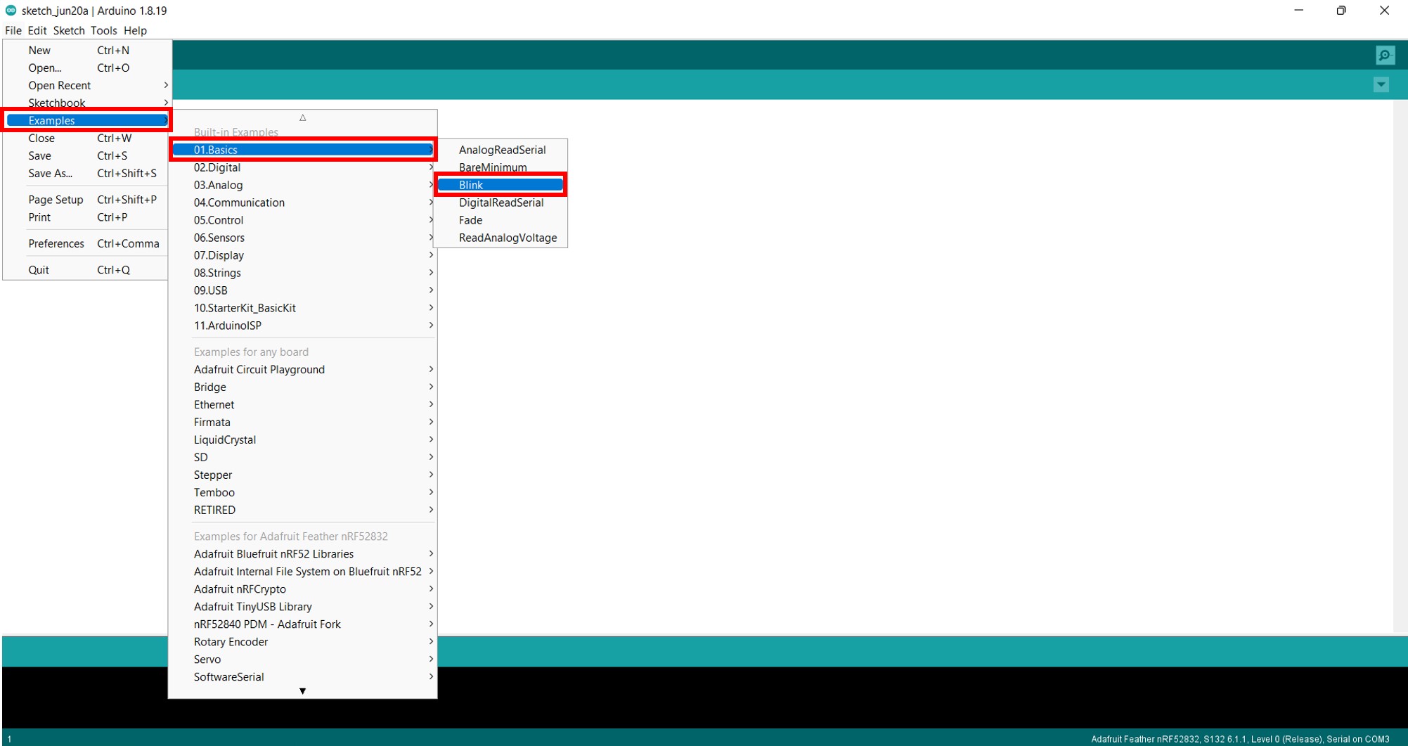
I started the process with something simple, I programmed the microcontroller board with the ‘Blink’ example code that is built into the Arduino IDE software (File > Examples > Basics > Blink).
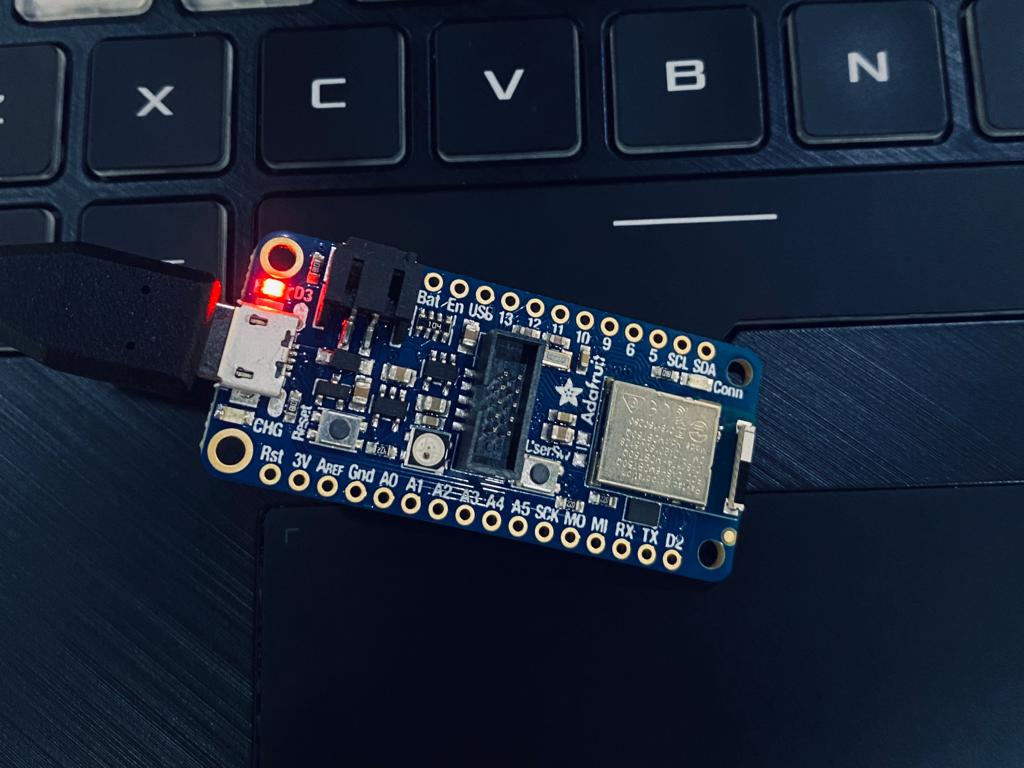
These are before blinking:
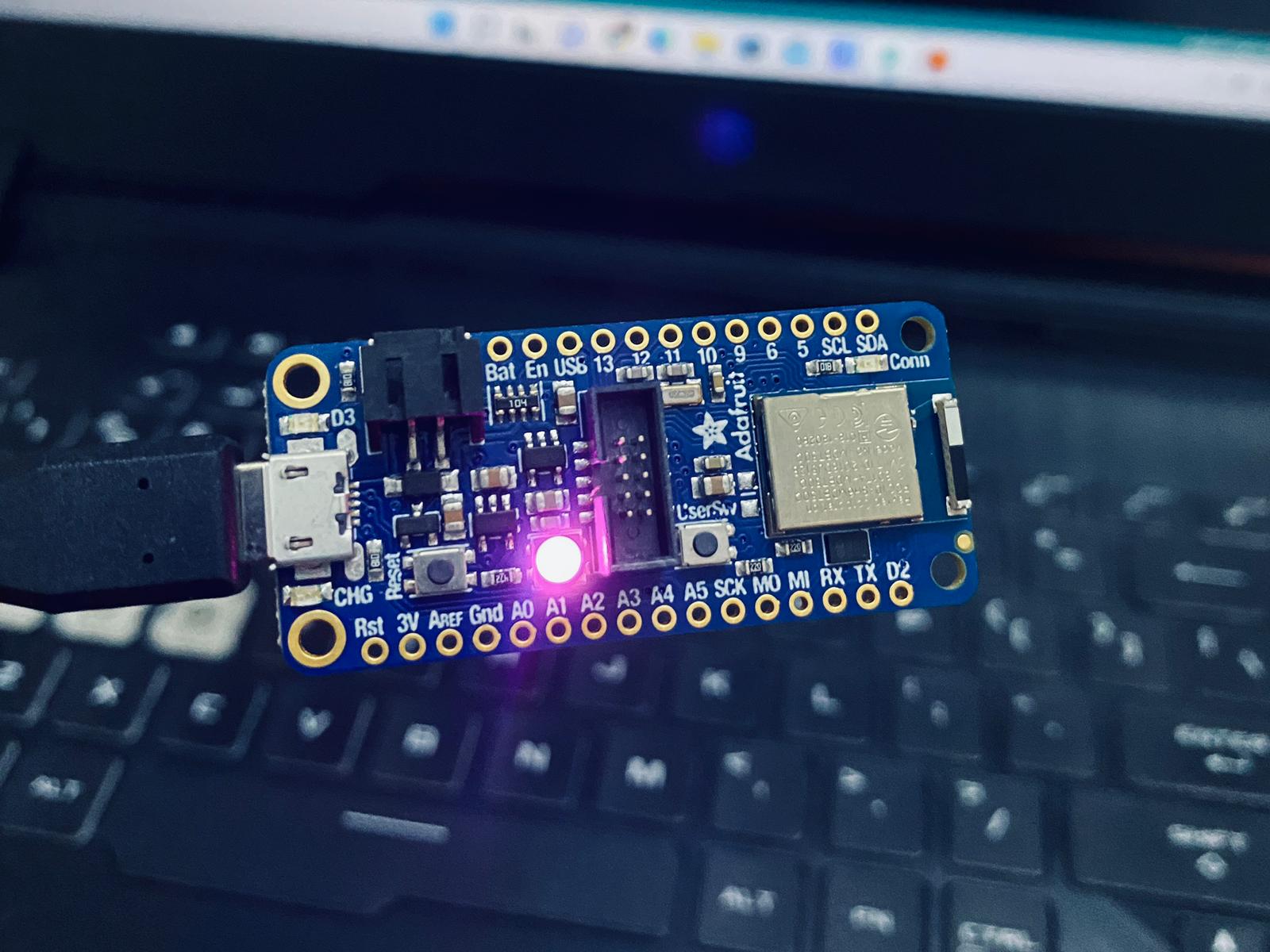
These are after blinking:
/*
  Blink

  Turns an LED on for one second, then off for one second, repeatedly.

  Most Arduinos have an on-board LED you can control. On the UNO, MEGA and ZERO
  it is attached to digital pin 13, on MKR1000 on pin 6. LED_BUILTIN is set to
  the correct LED pin independent of which board is used.
  If you want to know what pin the on-board LED is connected to on your Arduino
  model, check the Technical Specs of your board at:
  https://www.arduino.cc/en/Main/Products

  modified 8 May 2014
  by Scott Fitzgerald
  modified 2 Sep 2016
  by Arturo Guadalupi
  modified 8 Sep 2016
  by Colby Newman

  This example code is in the public domain.

  https://www.arduino.cc/en/Tutorial/BuiltInExamples/Blink
*/

// the setup function runs once when you press reset or power the board
void setup() {
  // initialize digital pin LED_BUILTIN as an output.
  pinMode(LED_BUILTIN, OUTPUT);
}

// the loop function runs over and over again forever
void loop() {
  digitalWrite(LED_BUILTIN, HIGH);   // turn the LED on (HIGH is the voltage level)
  delay(1000);                       // wait for a second
  digitalWrite(LED_BUILTIN, LOW);    // turn the LED off by making the voltage LOW
  delay(1000);                       // wait for a second
}
Here is a longer code for blinking which uses different timings.
/*
  Blink

  Turns an LED on for one second, then off for one second, repeatedly.

  Most Arduinos have an on-board LED you can control. On the UNO, MEGA and ZERO
  it is attached to digital pin 13, on MKR1000 on pin 6. LED_BUILTIN is set to
  the correct LED pin independent of which board is used.
  If you want to know what pin the on-board LED is connected to on your Arduino
  model, check the Technical Specs of your board at:
  https://www.arduino.cc/en/Main/Products

  modified 8 May 2014
  by Scott Fitzgerald
  modified 2 Sep 2016
  by Arturo Guadalupi
  modified 8 Sep 2016
  by Colby Newman

  This example code is in the public domain.

  https://www.arduino.cc/en/Tutorial/BuiltInExamples/Blink
*/

// the setup function runs once when you press reset or power the board
void setup() {
  // initialize digital pin LED_BUILTIN as an output.
  pinMode(LED_BUILTIN, OUTPUT);
}

// the loop function runs over and over again forever
void loop() {
  digitalWrite(LED_BUILTIN, HIGH);   // turn the LED on (HIGH is the voltage level)
  delay(1000);                       // wait for a second
  digitalWrite(LED_BUILTIN, LOW);    // turn the LED off by making the voltage LOW
  delay(500);                       // wait for a second

  digitalWrite(LED_BUILTIN, HIGH);   // turn the LED on (HIGH is the voltage level)
  delay(2000);                       // wait for a second
  digitalWrite(LED_BUILTIN, LOW);    // turn the LED off by making the voltage LOW
  delay(1000);                       // wait for a second

  digitalWrite(LED_BUILTIN, HIGH);   // turn the LED on (HIGH is the voltage level)
  delay(3000);                       // wait for a second
  digitalWrite(LED_BUILTIN, LOW);    // turn the LED off by making the voltage LOW
  delay(1500);                       // wait for a second

    digitalWrite(LED_BUILTIN, HIGH);   // turn the LED on (HIGH is the voltage level)
  delay(4000);                       // wait for a second
  digitalWrite(LED_BUILTIN, LOW);    // turn the LED off by making the voltage LOW
  delay(2000);                       // wait for a second
}
TinkerCAD
We used TinkerCAD as another software for coding and programming the microcontroller. It is a free web app for 3D design, electronics, and coding.
After exploring TinkerCAD, we moved on to morsecode.world website in order to translate a word into a morse code as you can see below.
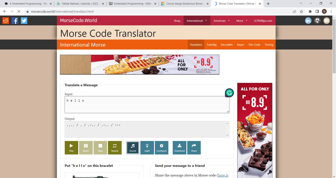
Then, I used the above output (.... / . / .-.. / .-.. / —) to build the code in TinkerCAD using the blocks mode.
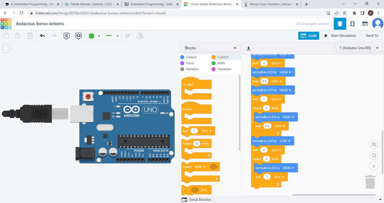
Finally, I downloaded the code into Arduino and uploaded it into my microcontroller.
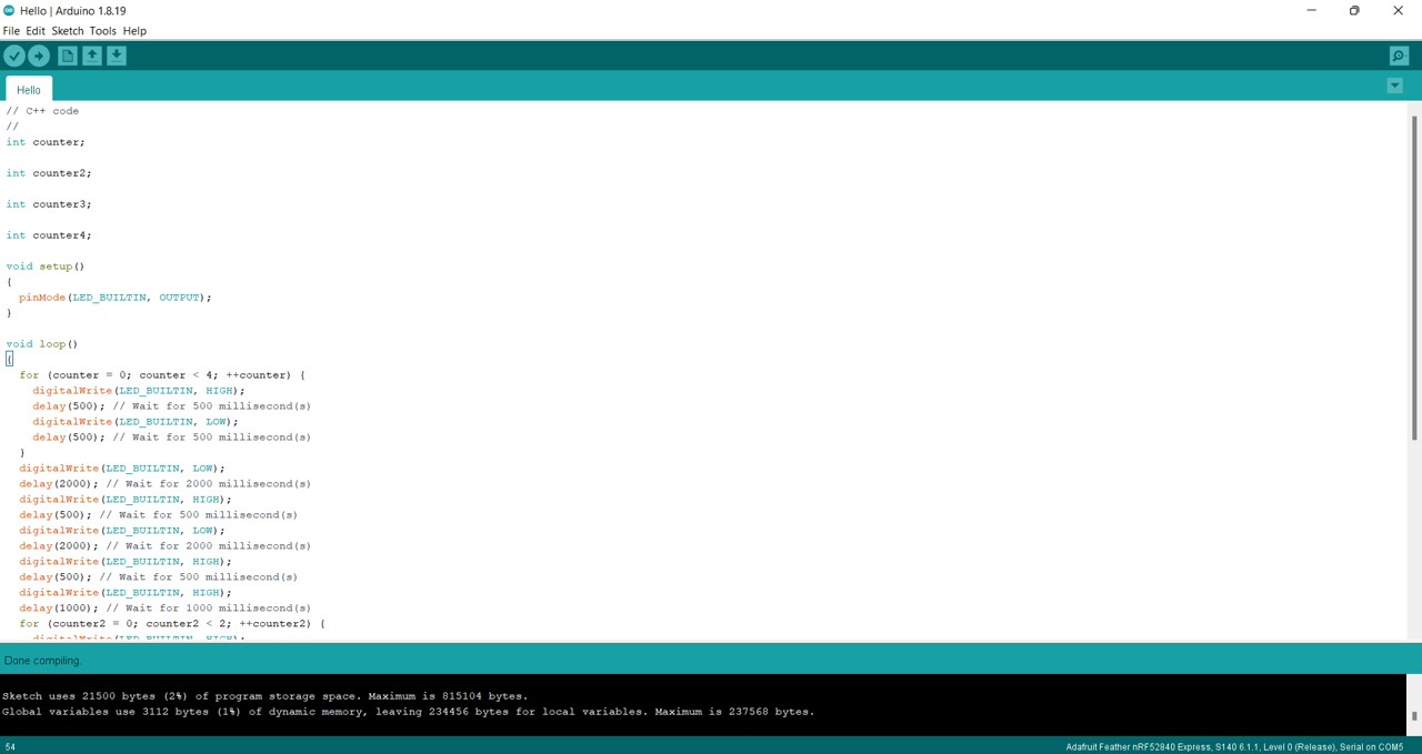
// C++ code
//
int counter;

int counter2;

int counter3;

int counter4;

void setup()
{
  pinMode(LED_BUILTIN, OUTPUT);
}

void loop()
{
  for (counter = 0; counter < 4; ++counter) {
    digitalWrite(LED_BUILTIN, HIGH);
    delay(500); // Wait for 500 millisecond(s)
    digitalWrite(LED_BUILTIN, LOW);
    delay(500); // Wait for 500 millisecond(s)
  }
  digitalWrite(LED_BUILTIN, LOW);
  delay(2000); // Wait for 2000 millisecond(s)
  digitalWrite(LED_BUILTIN, HIGH);
  delay(500); // Wait for 500 millisecond(s)
  digitalWrite(LED_BUILTIN, LOW);
  delay(2000); // Wait for 2000 millisecond(s)
  digitalWrite(LED_BUILTIN, HIGH);
  delay(500); // Wait for 500 millisecond(s)
  digitalWrite(LED_BUILTIN, HIGH);
  delay(1000); // Wait for 1000 millisecond(s)
  for (counter2 = 0; counter2 < 2; ++counter2) {
    digitalWrite(LED_BUILTIN, HIGH);
    delay(500); // Wait for 500 millisecond(s)
  }
  digitalWrite(LED_BUILTIN, LOW);
  delay(2000); // Wait for 2000 millisecond(s)
  digitalWrite(LED_BUILTIN, HIGH);
  delay(500); // Wait for 500 millisecond(s)
  digitalWrite(LED_BUILTIN, HIGH);
  delay(1000); // Wait for 1000 millisecond(s)
  for (counter3 = 0; counter3 < 2; ++counter3) {
    digitalWrite(LED_BUILTIN, HIGH);
    delay(500); // Wait for 500 millisecond(s)
  }
  digitalWrite(LED_BUILTIN, LOW);
  delay(2000); // Wait for 2000 millisecond(s)
  for (counter4 = 0; counter4 < 3; ++counter4) {
    digitalWrite(LED_BUILTIN, HIGH);
    delay(1000); // Wait for 1000 millisecond(s)
  }
}
Challenges
Easy Mode
“Blink your led but have your blink delay periods be randomized values between 1 second and 5 seconds.”
Solution:
// the setup function runs once when you press reset or power the board
void setup() {
  // initialize digital pin LED_BUILTIN as an output.
  pinMode(LED_BUILTIN, OUTPUT);
}

// the loop function runs over and over again forever
void loop() {
  digitalWrite(LED_BUILTIN, HIGH);   // turn the LED on (HIGH is the voltage level)
  delay (1000*random(1,5+1));         // wait for a second
  digitalWrite(LED_BUILTIN, LOW);    // turn the LED off by making the voltage LOW
  delay (1000*random(1,5+1));         // wait for a second
}
Medium Mode
“Pre code your microcontroller to send a Morse code 1 word message and challenge a friend, family member, your colleagues or your instructor to figure it out.”
Dot = 0.5 second light on.
Dash = 1 second light on.
Gap between dots and dashes = 0.5 second light off.
Gap between letters = 2 second light off
Solution: Kindly, refer back to the TinkerCAD documentation.
Hard Mode
“You select the duration of the light being on and off while the program is running by entering it in the serial monitor. Write a code that takes the data from the serial monitor and delays by that amount of time.”
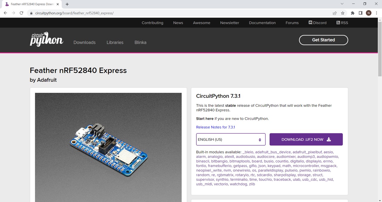
Python
“Python is a high-level, interpreted, general-purpose programming language” and it was introduced to us as a third option to program our microcontroller.
First, I downloaded CircuitPython and Mu Editor as shown in the below images.
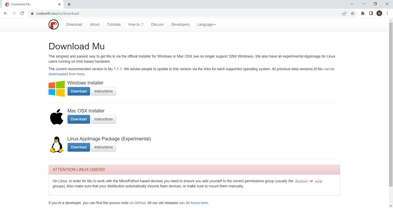
After that, I searched how to blink the LED within my microcontroller using the Mu Editor. However, on the Adafruit website, I figured out that I have to do several steps first in order to successfully install the CircuitPython on my computer.
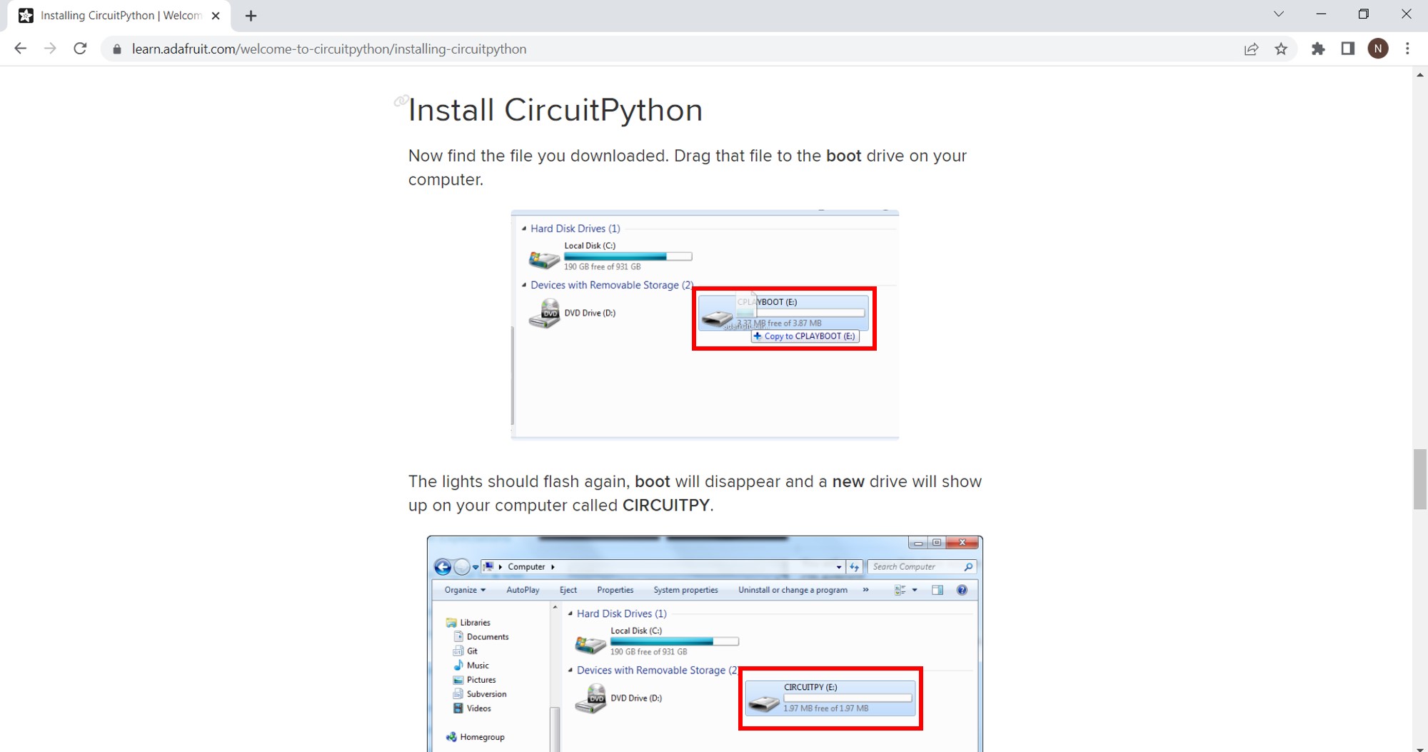
Finally, I followed the steps for ‘Creating and Editing Codes’ provided on the Adafruit website. Downloaded the file, and copied and pasted the code into my editor.
import board
import digitalio
import time

led = digitalio.DigitalInOut(board.LED)
led.direction = digitalio.Direction.OUTPUT

while True:
    led.value = True
    time.sleep(0.5)
    led.value = False
    time.sleep(0.5)
And it is successfully blinking!
General Notes
-
The light grey text in Arduino IDE is just a comment and it does not affect the code.
-
Use the repeat block option in TinkerCAD to make your work easier and faster.
-
In order for the port in Arduino IDE to work, your PC should be connected to the microcontroller board.
-
Do not forget to double click on the reset button on the board itself every time you change the code in Arduino IDE.
-
The code that you put inside void setup() will only run once, and that will be at the beginning of your program while in void loop(), your code will repeat over and over again.
-
A normal circuit is usually connected to a battery. However, in this case, it is connected to a USB and there is no human intervention. In other words, the code is deciding the whole process.
Personal Opinion
References
Adafruit Industries (2019). Adafruit Feather nRF52840 Express. [online] Adafruit.com. Available at: Click Here [Accessed 18 Jun. 2022].
Adafruit Learning System. (n.d.). Introducing the Adafruit nRF52840 Feather. [online] Available at: Click Here [Accessed 19 Jun. 2022].
IoT Agenda. (n.d.). What is a Microcontroller and How Does it Work? [online] Available at: Click Here [Accessed 19 Jun. 2022].