7. Input & Output device
This week we worked on programming input and output devices, each one separately.
Introduction
“An input device sends information to a computer system for processing, and an output device reproduces or displays the results of that processing. Input devices only allow for the input of data to a computer and output devices only receive the output of data from another device.”
Examples of input devices: Mouse, keyboard, web cam, microphone, etc.
Examples of output devices: Projector, monitor, speaker, printer, etc.

Individual Assignment
For the individual assignment, we were asked to add a sensor to a microcontroller board and read it. Also, we were asked to add an output device and program it to do something.
Input Device
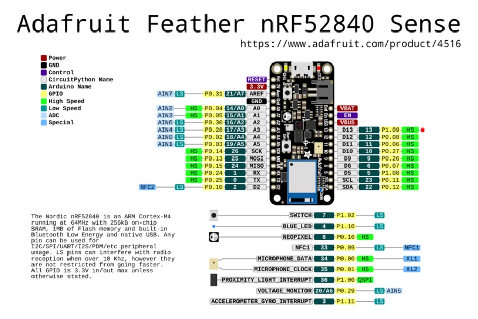
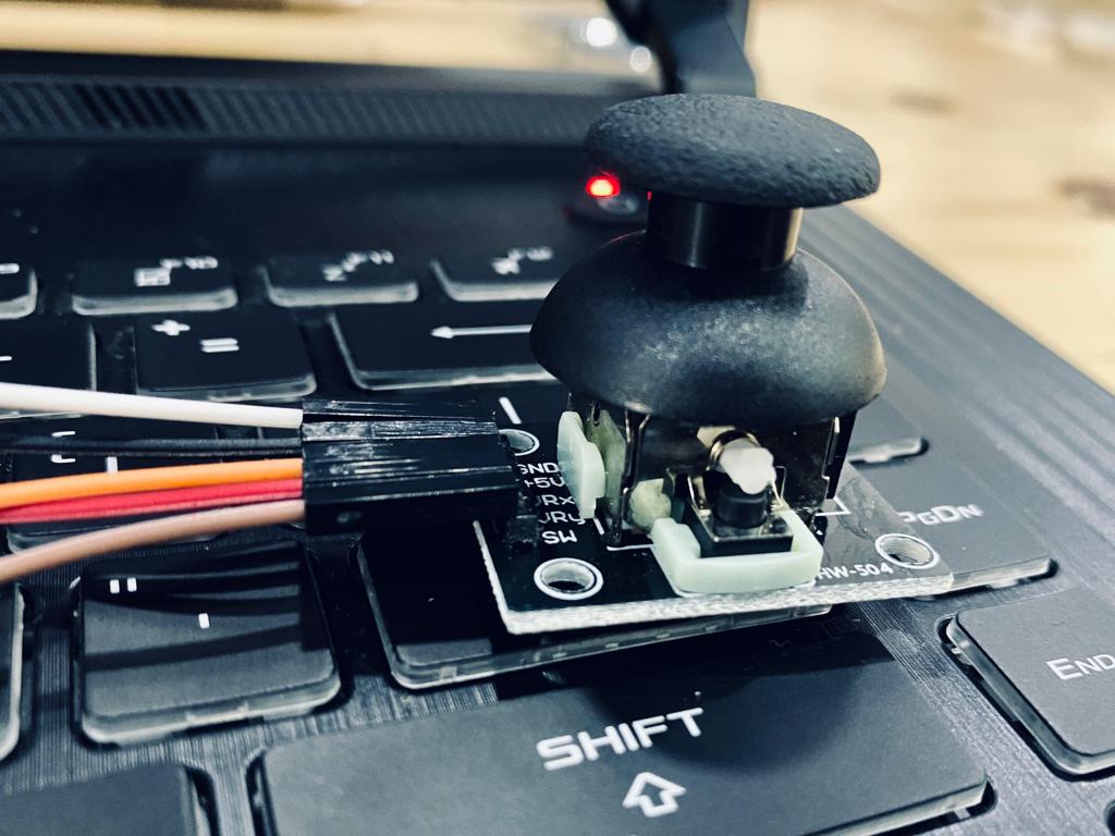
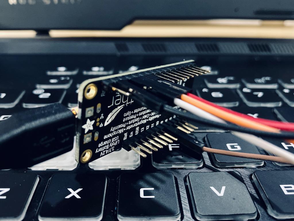
For the input device, I had a 2-Axis Joystick sensor and Adafruit Feather nRF52840 Sense microcontroller.
2-Axis Joystick
“It is very similar to the ‘analog’ joysticks on PS2 (PlayStation 2) controllers. It is a self-centering spring loaded joystick, meaning when you release the joystick it will center itself. It also contains a comfortable cup-type knob/cap which gives the feel of a thumb-stick.”

Programming
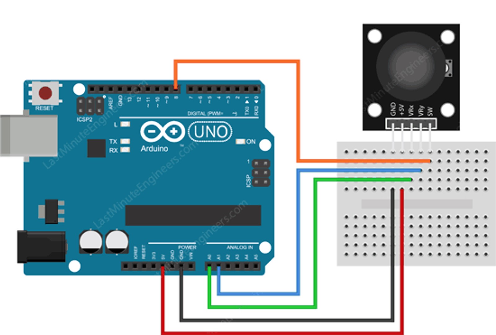
So first, I searched about the pinouts of both devices and how to connect them together as shown in the images below.
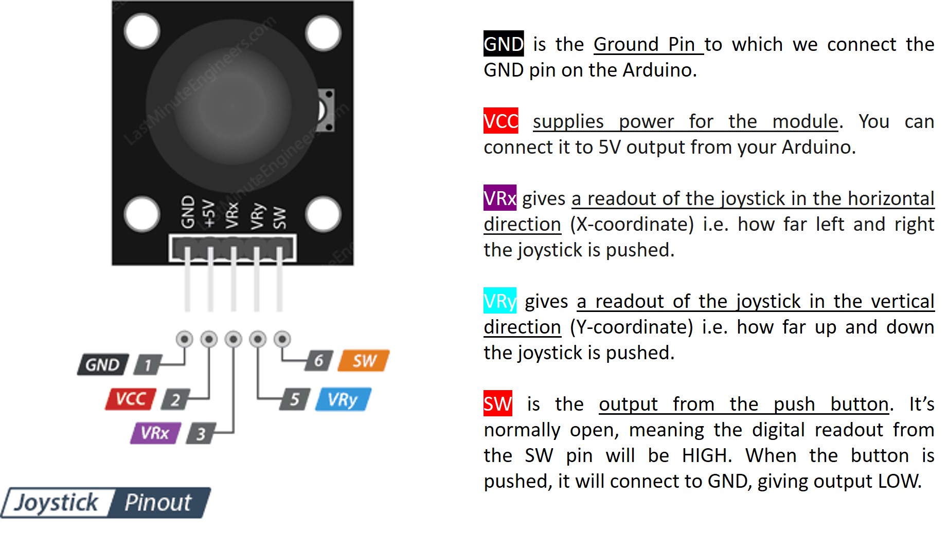
This schematic diagram of the Joystick shows that each pin has a different function and has to be connected with a specific pin on the Arduino Uno.
Second, I connected the Joystick with the microcontroller using wires as the following:
Third, I copied the pre-made code that I found on the Last Minute Engineers website and paste it into Arduino software.
// Arduino pin numbers
const int SW_pin = 8; // digital pin connected to switch output
const int X_pin = 0; // analog pin connected to X output
const int Y_pin = 1; // analog pin connected to Y output

void setup() {
  pinMode(SW_pin, INPUT);
  digitalWrite(SW_pin, HIGH);
  Serial.begin(9600);
}

void loop() {
  Serial.print("Switch:  ");
  Serial.print(digitalRead(SW_pin));
  Serial.print(" | ");
  Serial.print("X-axis: ");
  Serial.print(analogRead(X_pin));
  Serial.print(" | ");
  Serial.print("Y-axis: ");
  Serial.print(analogRead(Y_pin));
  Serial.println(" | ");
  delay(200);
}
It did not work from the first time because the software could not recognize the word “serial” that was included in the code, and to solve that error I had to include a library (Sketch > Include Library > Software Serial).

After that, unfortunately, it did not work as well. However, I noticed that I have to change X and Y pins from 0 and 1 into A0 and A1.
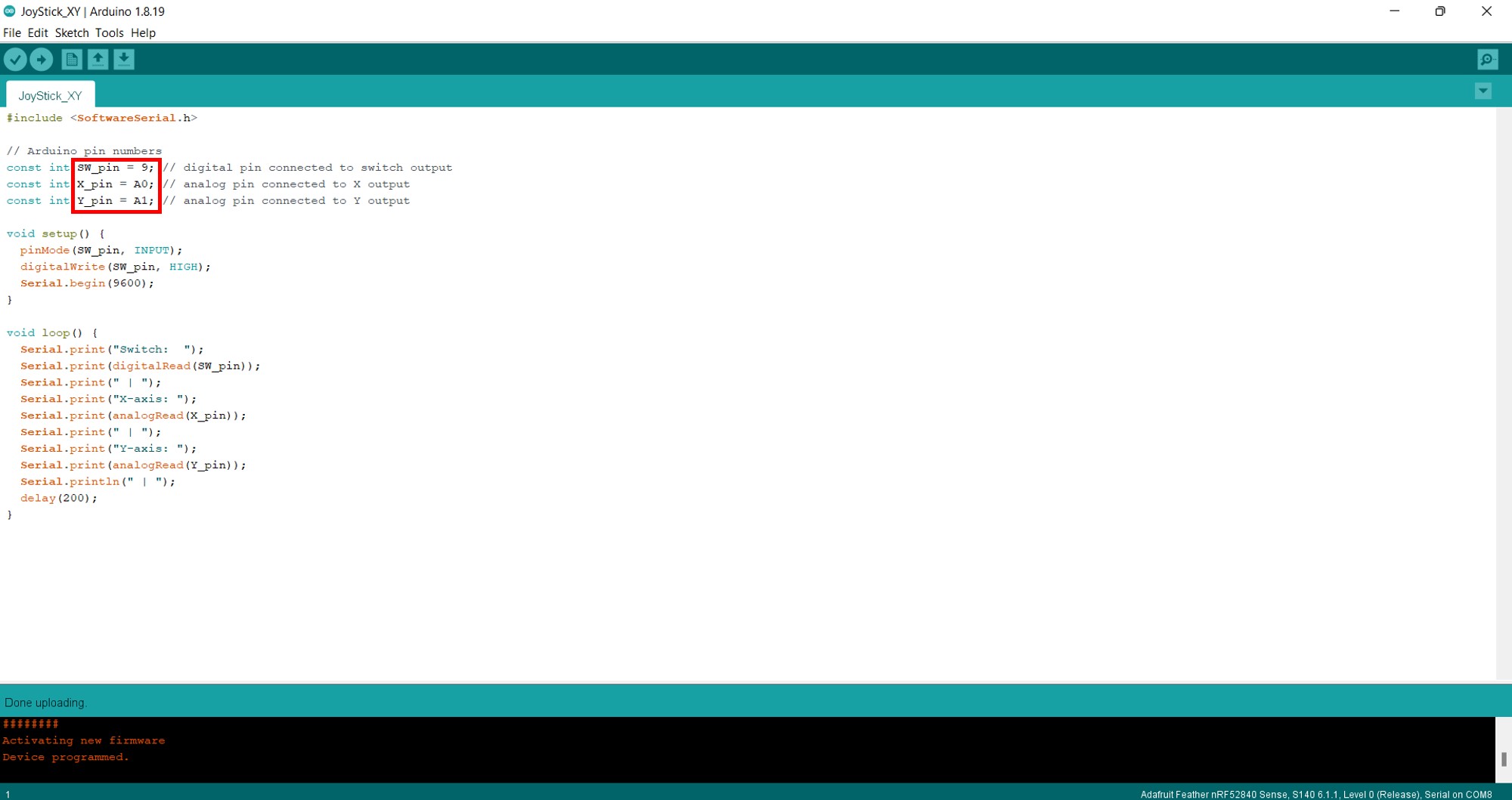
Finally, it worked successfully and I saw the Joystick module output on the serial monitor.

Code Explanation
How does the above code work?
“The sketch starts by initializing connections of Joystick module on the Arduino. The SW pin is connected to Arduino Pin#8 while the VRx and VRy pins are connected to Analog pin #0 and #1.”
// Arduino pin numbers
const int SW_pin = 8; // digital pin connected to switch output
const int X_pin = 0; // analog pin connected to X output
const int Y_pin = 1; // analog pin connected to Y output
“In setup() function: We initialize the SW pin as an input and keep it HIGH. This is because as long as the SW pin is HIGH, we know that the button is not pressed. We also start the serial communication.”
pinMode(SW_pin, INPUT);
  digitalWrite(SW_pin, HIGH);
  Serial.begin(9600);
“In loop() function: We merely read the value of SW pin using digitalRead() function, VRx & VRy pin using analogRead() and display on serial monitor.”
Serial.print("Switch:  ");
  Serial.print(digitalRead(SW_pin));
  Serial.print(" | ");
  Serial.print("X-axis: ");
  Serial.print(analogRead(X_pin));
  Serial.print(" | ");
  Serial.print("Y-axis: ");
  Serial.print(analogRead(Y_pin));
  Serial.println(" | ");
  delay(200);
Output Device
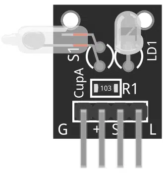
For the output device, I had a KY-027 Magic Light Cup (a mercury switch) and Adafruit Feather nRF52840 Sense microcontroller.
Mercury Switch
“It is a type of switch wherein the contacts are closed by a blob of mercury. If the switch is tilted, the mercury will flow and will open the contacts.”
Programming
I followed the same procedure I did for the input device, so first I searched for the wiring diagram and the connection between the Arduino Uno and the KY-027 Magic Light Cup Module.

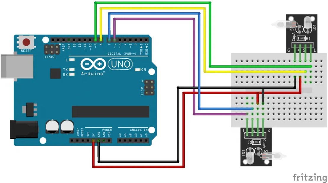
Here you can see part of the connection.

I used a pre-made code that is available on Arduino Modules website to run the device and it worked successfully from the first time.
int ledPinA = 9;
int switchPinA = 8;
int switchStateA = 0;
int ledPinB = 6;
int switchPinB = 7;
int switchStateB = 0;
int brightness   = 0;
void setup()
{
  pinMode(ledPinA, OUTPUT);
  pinMode(ledPinB, OUTPUT);
  pinMode(switchPinA, INPUT);
  pinMode(switchPinB, INPUT);
}
void loop()
{
  switchStateA = digitalRead(switchPinA);
  if (switchStateA == HIGH && brightness != 255)
  {
   brightness ++;
  }
  switchStateB = digitalRead(switchPinB);
  if (switchStateB == HIGH && brightness != 0)
  {
   brightness --;
  }
  analogWrite(ledPinA, brightness);  //  A slow fade out
  analogWrite(ledPinB, 255 - brightness);  // B slow bright up
  delay(20);
}
Code Explanation
How does the above code work?
It basically controls the brightness of the LED by tilting the module. As for that, once you apply power to the microcontroller board, slowly tilt the module and the LED’s brightness will be dimmer. Also, when you bring it back upright the module, the LED will slowly become brighter as you can see in the attached video below.
Personal Opinion
This is one of the easiest weeks in the academy, even though I do not have any background in programming but I found it straightforward.
References
www.computerhope.com. (n.d.). What is the difference between an input and output device? [online] Available at: Click Here [Accessed 6 Jul. 2022].
Last Minute Engineers. (2018). In-Depth: How 2-Axis Joystick Works? Interface with Arduino & Processing. [online] Available at: Click Here [Accessed 6 Jul. 2022].
Electronics, P. (2020). Using the Magic Light Cup Module KY-027 with Arduino. [online] Phipps Electronics. Available at: Click Here [Accessed 6 Jul. 2022].