Final Project
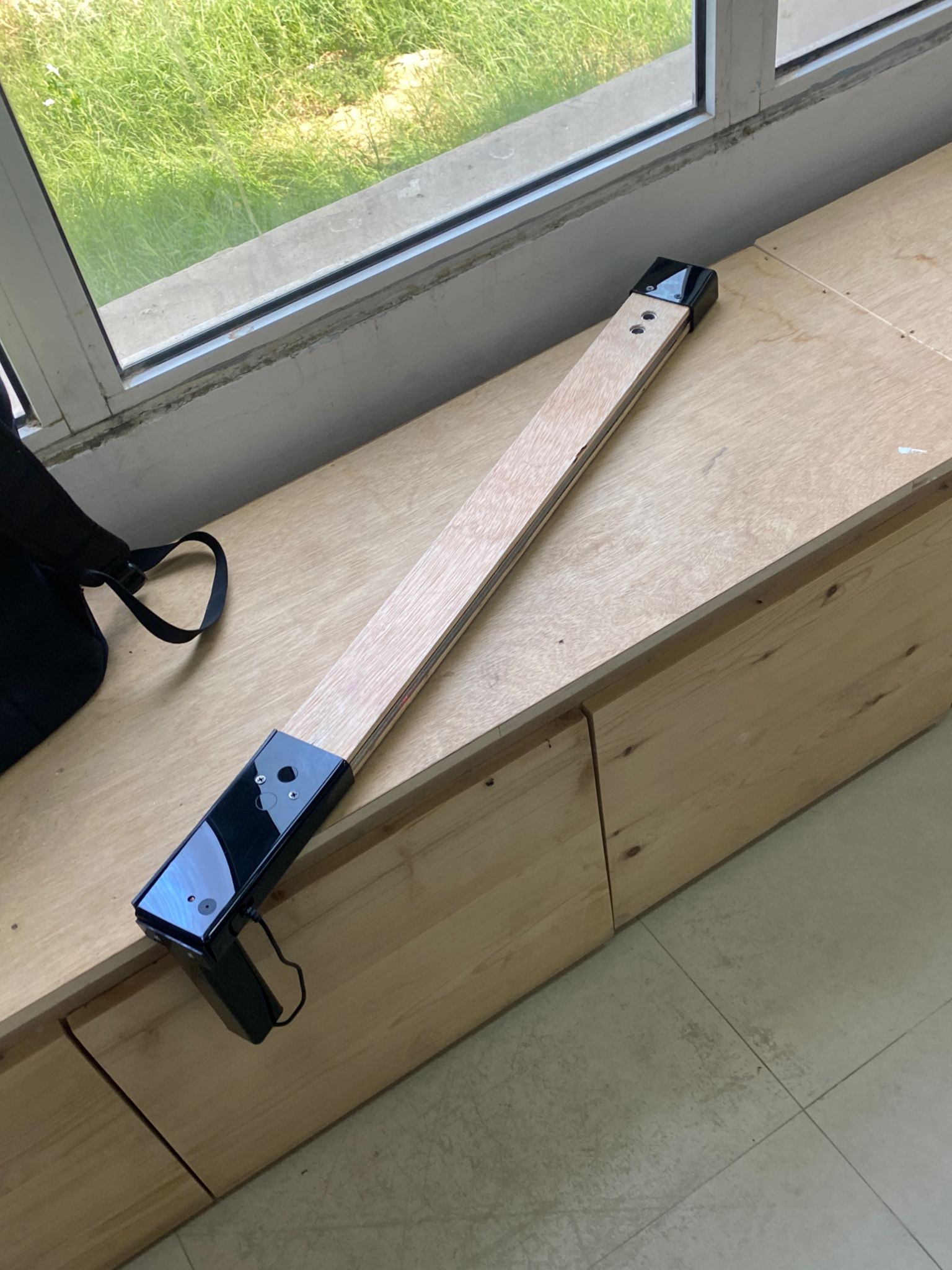
My coworker Nawraa and I started considering a project for the final project where we could use most of the knowledge we had learned throughout the course while also doing something that would benefit society rather than just our own needs. We came out with an idea which is a stick for visually impaired/ visually challenged people to help them through the day and make them more comfortable. You can learn more about the electronics and programming we used in this project on my page, and you can learn more about the design and the materials we used on Nawraa’s page
Project needs:
- Adafruit sense.
- Buzzer.
- 2 Ultrasonic.
- LED.
- LDR.
- Resistor.
Electronics:
Adafruit sense:
It is a small integrated circuit that controls a single function in an embedded system. On a single chip, a microcontroller has a CPU, memory, and input/output (I/O) peripherals.
Breadbord
How to Build Prototype Electronic Circuits - Circuit BasicsBreadboard is a flat board used as a base for connecting electronic components to build electronic circuits. and prototyping of electronic devices. It is solderless and reusable which makes it easy to use to create temporary models and drug design experiments. As shown in Figure 7 The board consists of a flat of non-conductive material, mostly plastic, and contains horizontal rows of slots connected horizontally to allow electronic components to be inserted into it. On the two sides, there are a number of other slots, but they are connected vertically for the purpose of using them to supply the circuit with power easily. In the middle of the board there is a slot of a certain width to allow the installation of integrated circuits and divides the board into two similar parts we use the breadboard to connect the components of the project together
Jumper wire
jump wire is an electrical wire, or group of them in a cable, with a connector or pin at each end, which is normally used to interconnect the components of a breadboard or other prototype or test circuit, internally or with other equipment or components, without soldering. Individual jump wires are fitted by inserting their “end connectors” into the slots provided in a breadboard, the header connector of a circuit board, or a piece of test equipment. These wire cone in three versions: male-to-male, male-to-female and female-to-female. The difference between each is in the end point of the wire. Male ends have a pin protruding and can plug into things, while the female doesn’t have this thing. In our project the first two version were used.
Buzzer
buzzers are economical yet dependable, and they are available in a variety of sizes and frequencies to satisfy the demands of practically any application. Piezoelectric buzzers are employed in electrical circuits to provide an alert tone because they are inexpensive and trustworthy. The piezoelectric component is the key feature that distinguishes this type of buzzer. Special materials that show the piezoelectric effect are used to make piezoelectric components, where the material can convert some energy from applied mechanical strain into an electric charge. These materials also show the reverse piezoelectric effect, which causes deformation when an electric charge is given to them. A piezo buzzer is made up of a piezo element, which is a tiny disk of piezoelectric ceramic that is bonded to a metal plate. A silver electrode is put to both sides of the piezoelectric element to allow for electrical contact. The entire system can be housed in a plastic box, with or without a driving circuit. Piezo buzzers operate by utilizing the reverse piezoelectric effect, which occurs when a material deforms in the presence of an electric charge. A piezo buzzer operates by passing an alternating voltage through a piezoelectric ceramic substance. When such an input signal is applied, the piezoceramic vibrates quickly, resulting in the creation of vibrations.
Ultrasonic
An ultrasonic sensor is a piece of technology that uses ultrasonic sound waves to measure a target object’s distance and then turns the sound that is reflected back into an electrical signal. The speed of audible sound is greater than the speed of ultrasonic waves (i.e. the sound that humans can hear). The transmitter (which emits sound using piezoelectric crystals) and the receiver are the two main parts of an ultrasonic sensor (which encounters the sound after it has travelled to and from the target). The sensor measures the amount of time that passes between the transmitter’s sound emission and its contact with the receiver in order to determine the distance between the object and the sensor. D = 12 T x C (where D is the distance, T is the time, and C is the sound speed of 343 meters per second) is the formula for this calculation. For instance, if a researcher placed an ultrasonic sensor at a box and waited 0.025 seconds for the sound to return, the distance between the object would be as follows:
D = 0.5 x 0.025 x 343
Most often, proximity sensors are used with ultrasonic sensors. They are present in anti-collision safety systems and self-parking automobile technology. Robotic obstacle detection systems and manufacturing technology both use ultrasonic sensors. Ultrasonic sensors in proximity sensing applications are less prone to interference from smoke, gas, and other airborne particles than infrared (IR) sensors are (though the physical components are still affected by variables such as heat). To detect, monitor, and control liquid levels in closed containers, ultrasonic sensors are also employed as level sensors (such as vats in chemical factories). Most significantly, ultrasound technology has made it possible for the medical sector to create images of internal organs, spot tumors, and guarantee the wellbeing of unborn children.
LED
A light-emitting diode (LED) is a semiconductor device that emits light when an electric current flows through it. When current passes through an LED, the electrons recombine with holes emitting light in the process. LEDs allow the current to flow in the forward direction and blocks the current in the reverse direction. Light-emitting diodes are heavily doped p-n junctions. Based on the semiconductor material used and the amount of doping, an LED will emit a coloured light at a particular spectral wavelength when forward biased. As shown in the figure, an LED is encapsulated with a transparent cover so that emitted light can come out. The colour of an LED is determined by the material used in the semiconducting element. The two primary materials used in LEDs are aluminium gallium indium phosphide alloys and indium gallium nitride alloys. Aluminium alloys are used to obtain red, orange and yellow light, and indium alloys are used to get green, blue and white light. Slight changes in the composition of these alloys change the colour of the emitted light.
LDR
The most common uses for photoresistors, also referred to as light dependent resistors (LDR), are to detect the presence or absence of light or to gauge the intensity of the light. When the LDR sensor is exposed to light, the resistance drops dramatically, sometimes even to a few ohms, depending on the light intensity. In the dark, their resistance is very high, sometimes reaching 1 M. LDRs are nonlinear devices with variable sensitivity depending on the wavelength of applied light. Although they are used in many applications, other gadgets like photodiodes and phototransistors frequently carry out this light sensing function. LDRs made of lead or cadmium have been outlawed in some nations due to environmental safety concerns.
Working principle
The buzzer sensor emits a warning sound when the ultrasonic sensor detects an object in front of it at a distance of about 60 meters, and it also sends a signal to the LED to turn on lighting when the LDR sensor detects no light(Other people will be able to see them walking in the dark thanks to the lighting.).
Connections
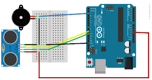
Ultrasonic & buzzer
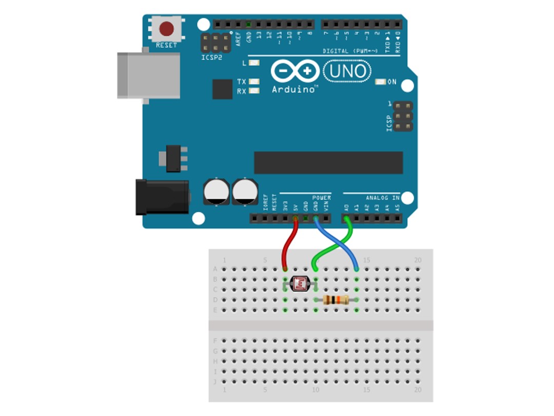
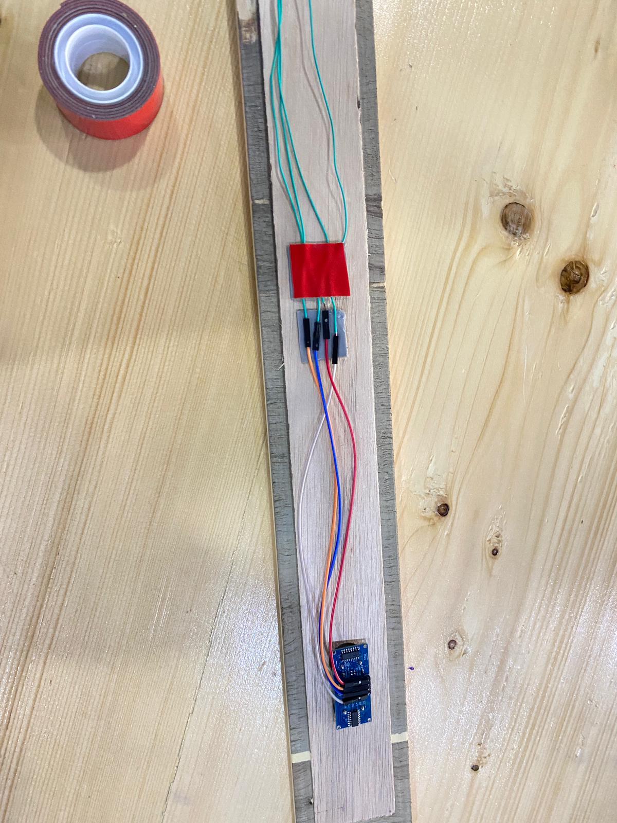
LDR, LED, and resistance
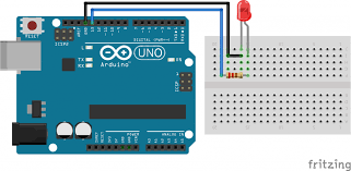 we had to weld the LED.
FullSizeRender.MOV from sukaina almansoor on Vimeo.
Coding
Ultrasonic and Buzzer
I started by programming the ultrasonic and the buzzer.
FullSizeRender.MOV from sukaina almansoor on Vimeo.
FullSizeRender.MOV from sukaina almansoor on Vimeo.
#include <SoftwareSerial.h>
const int trigPin = 9;
const int echoPin = 10;
const int Buzzer = 5;

long duration;
int distance;
int safetyDistance;

void setup() {
pinMode(trigPin, OUTPUT);
pinMode(echoPin, INPUT);
pinMode(Buzzer, OUTPUT);
Serial.begin(9600);
}

void loop (){

  digitalWrite(trigPin, LOW);
  delayMicroseconds(2);
  digitalWrite(trigPin, HIGH);
  delayMicroseconds(10);
  digitalWrite(trigPin, LOW);
  duration = pulseIn(echoPin, HIGH);
  distance= duration*0.034/2;
  safetyDistance = distance;
if (safetyDistance <= 30){
  tone(Buzzer,1000,200);
  delay(4000);
  }
else{
  noTone(Buzzer);
}
   Serial.print("Distance: ");
  Serial.println(distance);

}
LDR and LED
IMG_1045.MOV from sukaina almansoor on Vimeo.
 int LDR = analogRead(A0);
    Serial.println(LDR);
  delay(1);
   if (LDR <= 400) {
  strip.fill(white , 1 , 0);
   strip.show();
  strip.fill(white , 2 , 0);
   strip.show();
  strip.fill(white , 3 , 0);
   strip.show();
  strip.fill(white , 4 , 0);
   strip.show();
  strip.fill(white , 5 , 0);
   strip.show();
  strip.fill(white , 6 , 0);
   strip.show();
   strip.fill(white , 7 , 0);
   strip.show();
   strip.fill(white , 0 , 0);
   strip.show();
  }
  else {
    strip.fill(A , 1 , 0);
   strip.show();
  strip.fill(A , 2 , 0);
   strip.show();
  strip.fill(A , 3 , 0);
   strip.show();
  strip.fill(A , 4 , 0);
   strip.show();
  strip.fill(A , 5 , 0);
   strip.show();
  strip.fill(A , 6 , 0);
   strip.show();
   strip.fill(A , 7 , 0);
   strip.show();
   strip.fill(A , 0 , 0);
   strip.show();

  }
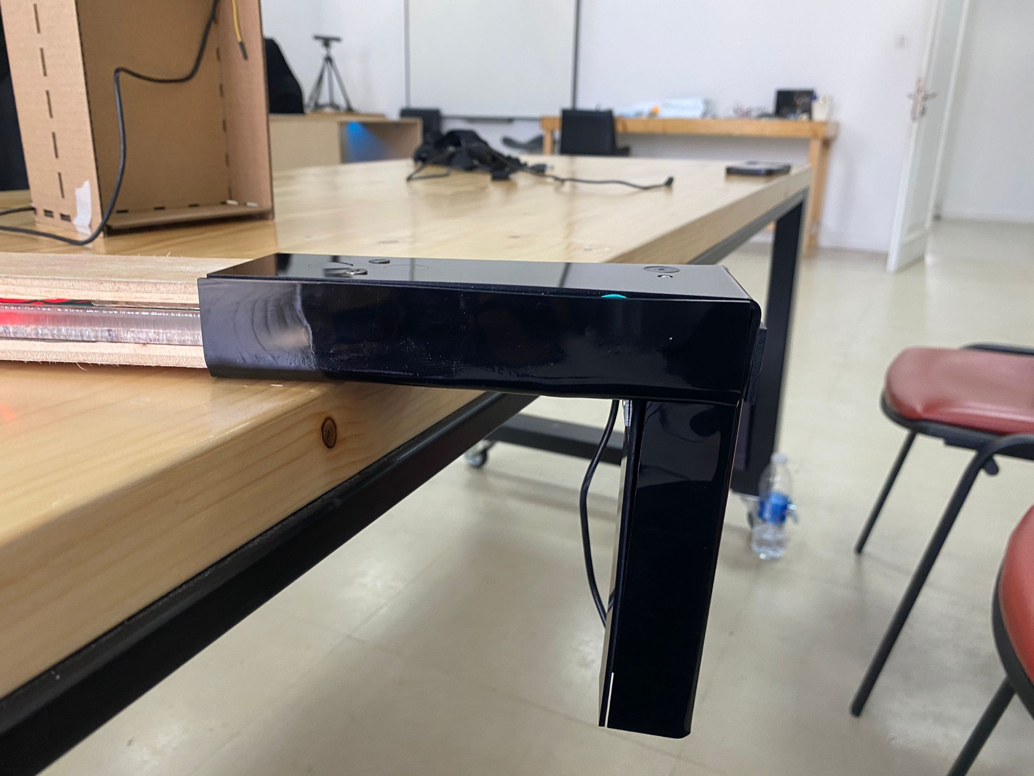
Final look
Full Code
#include <SoftwareSerial.h>
#include <Adafruit_NeoPixel.h>
#ifdef __AVR__
 #include <avr/power.h>
#endif


#define LED_PIN    5


#define LED_COUNT 8


const int trigPin1 = 11;
const int echoPin1 = 10;
const int Buzzer = 12;

long duration;
int distance;
int safetyDistance;
Adafruit_NeoPixel strip(LED_COUNT, LED_PIN, NEO_GRB + NEO_KHZ800);
uint32_t white = strip.Color(250,250,210);
uint32_t A = strip.Color(0,0,0);
void setup() {
pinMode(trigPin1, OUTPUT);
pinMode(echoPin1, INPUT);
pinMode(Buzzer, OUTPUT);
#if defined(__AVR_ATtiny85__) && (F_CPU == 16000000)
  clock_prescale_set(clock_div_1);
#endif


  strip.begin();
  strip.show();
  strip.setBrightness(30);
Serial.begin(9600);
}

void loop (){

  digitalWrite(trigPin1, LOW);
  delayMicroseconds(2);
  digitalWrite(trigPin1, HIGH);
  delayMicroseconds(10);
  digitalWrite(trigPin1, LOW);
  duration = pulseIn(echoPin1, HIGH);
  distance= duration*0.034/2;
  safetyDistance = distance;
  Serial.println(safetyDistance);

if (safetyDistance <= 60){
  tone(Buzzer,1100,200);
  delay(400);
  }
else{
  noTone(Buzzer);
}


 int LDR = analogRead(A0);
    Serial.println(LDR);
  delay(1);
   if (LDR <= 400) {
  strip.fill(white , 1 , 0);
   strip.show();
  strip.fill(white , 2 , 0);
   strip.show();
  strip.fill(white , 3 , 0);
   strip.show();
  strip.fill(white , 4 , 0);
   strip.show();
  strip.fill(white , 5 , 0);
   strip.show();
  strip.fill(white , 6 , 0);
   strip.show();
   strip.fill(white , 7 , 0);
   strip.show();
   strip.fill(white , 0 , 0);
   strip.show();
  }
  else {
    strip.fill(A , 1 , 0);
   strip.show();
  strip.fill(A , 2 , 0);
   strip.show();
  strip.fill(A , 3 , 0);
   strip.show();
  strip.fill(A , 4 , 0);
   strip.show();
  strip.fill(A , 5 , 0);
   strip.show();
  strip.fill(A , 6 , 0);
   strip.show();
   strip.fill(A , 7 , 0);
   strip.show();
   strip.fill(A , 0 , 0);
   strip.show();

  }
}
Issues we faced
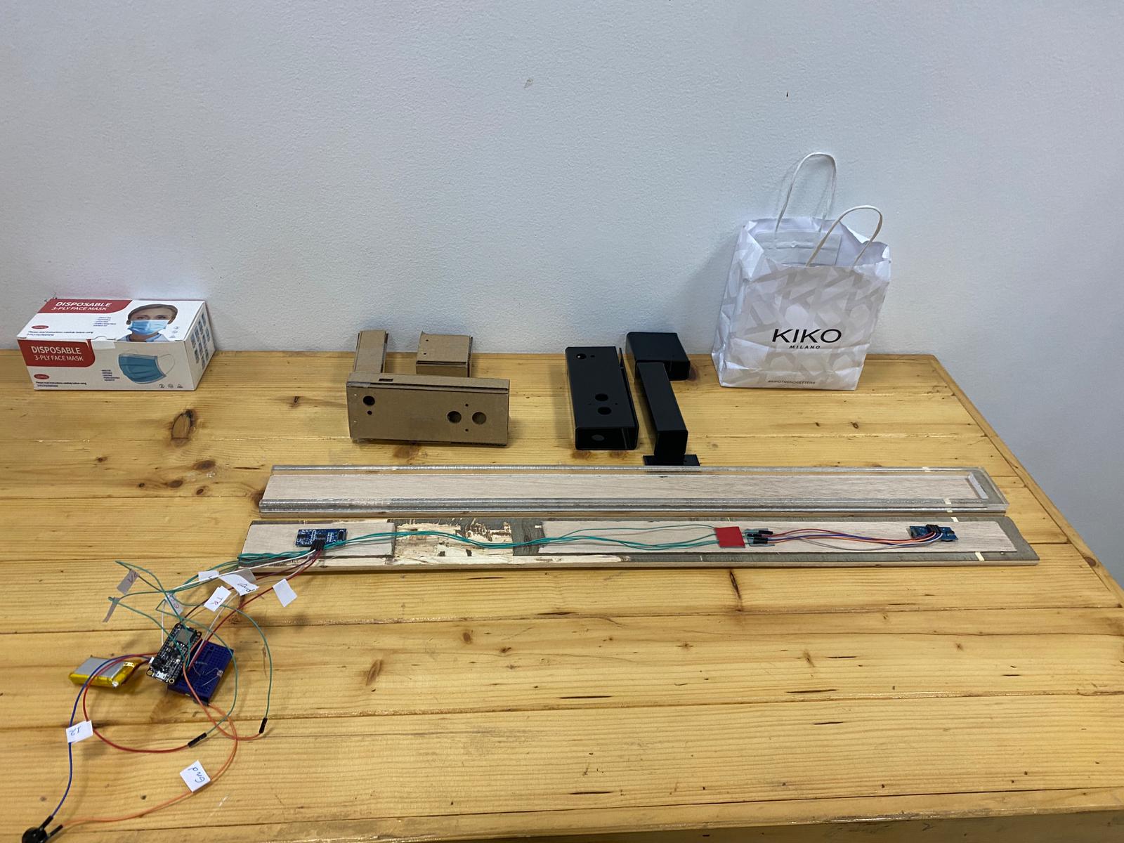
Design problems
When the stick was finished, we arranged the wires and electronics so they would fit inside, but we ran into a lot of problems doing that, like how to conceal the wires and how one of the ultrasonics won’t fit through the hole. Then, we discover a solution for these problems, which you can find on Nawraa’s page.
Codding problems:
As I was programming the LED, I ran into some problems. For instance, it didn’t function at all, but after adding the library and making some changes to the code, it started to work, just not in the color I wanted. I had to find the degree of color first, then write it in the code. Connecting the resistance, LED, and LDR also gave me trouble. I asked one of Fablab Academy member for help, and I found it was simple.
How do I feel about the project
Though I had higher expectations, this was my first project, so it’s okay if it’s not perfect. In fact, I’m very pleased with what I accomplished and feel that it was a great. But the most important thing is that I learned a lot from this project and the entire course.