6. Large format CNC (computer controlled Machining)
Week 8
In the manufacturing process known as CNC machining, factory equipment and tools are moved by computer programs that have been preprogrammed. The technique can be used to operate a wide variety of complex machinery, including mills, CNC routers, grinders, and lathes. When using CNC machining, three-dimensional cutting tasks can be finished in a single set of instructions.
How Does CNC Machining Work?
When a CNC system is activated, the desired cuts are programmed into the software and dictated to corresponding tools and machinery, which carry out the dimensional tasks as specified, much like a robot. In CNC programming, the code generator within the numerical system will often assume mechanisms are flawless, despite the possibility of errors, which is greater whenever a CNC machine is directed to cut in more than one direction simultaneously. The placement of a tool in a numerical control system is outlined by a series of inputs known as the part program. With a numerical control machine, programs are inputted via punch cards. By contrast, the programs for CNC machines are fed to computers through small keyboards. CNC programming is retained in a computer’s memory. The code itself is written and edited by programmers. Therefore, CNC systems offer far more expansive computational capacity. Best of all, CNC systems are by no means static since newer prompts can be added to pre-existing programs through revised code.
Material options
1- Acrylic. 2- Wood. 3- Rigid foam. 4- Aluminum. 5- Gypsum.
Drill bits:
- End mill
- Ball end mill
- Straight end mill
- V-carve bit We used the end mill for this week also the height of the millet is 6mm.
Feeds is the speed of movement and RPM is the rate per minutes .
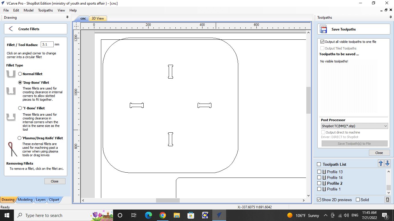
The machine is constrained. Use a T-bone or dog-bone to deal with this problem if your joints are 90 degrees.
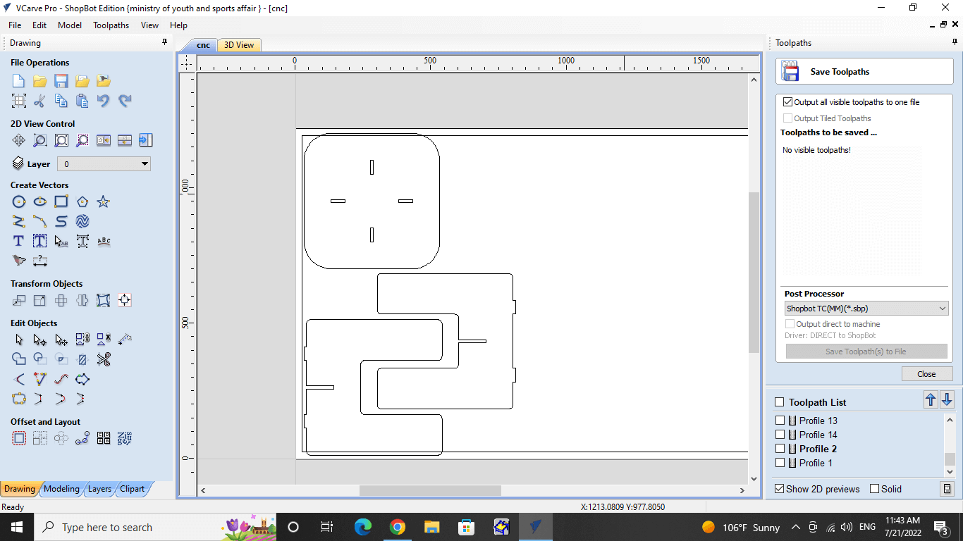
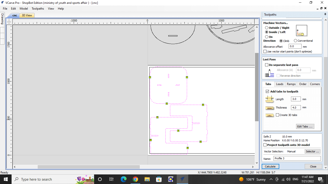
Toolpath:
is the path that a cutting tool’s tip takes through space as it shapes the workpiece to the desired geometry.
Joints:
There are many different types of joints, but we used three different 90-degree clearances with their corresponding dimensions for use with sheets of wood that are 12 mm thick. To solve the joints problem we either use th T-bone or dog bone, in my design I used the dog bone.
Group Assignment
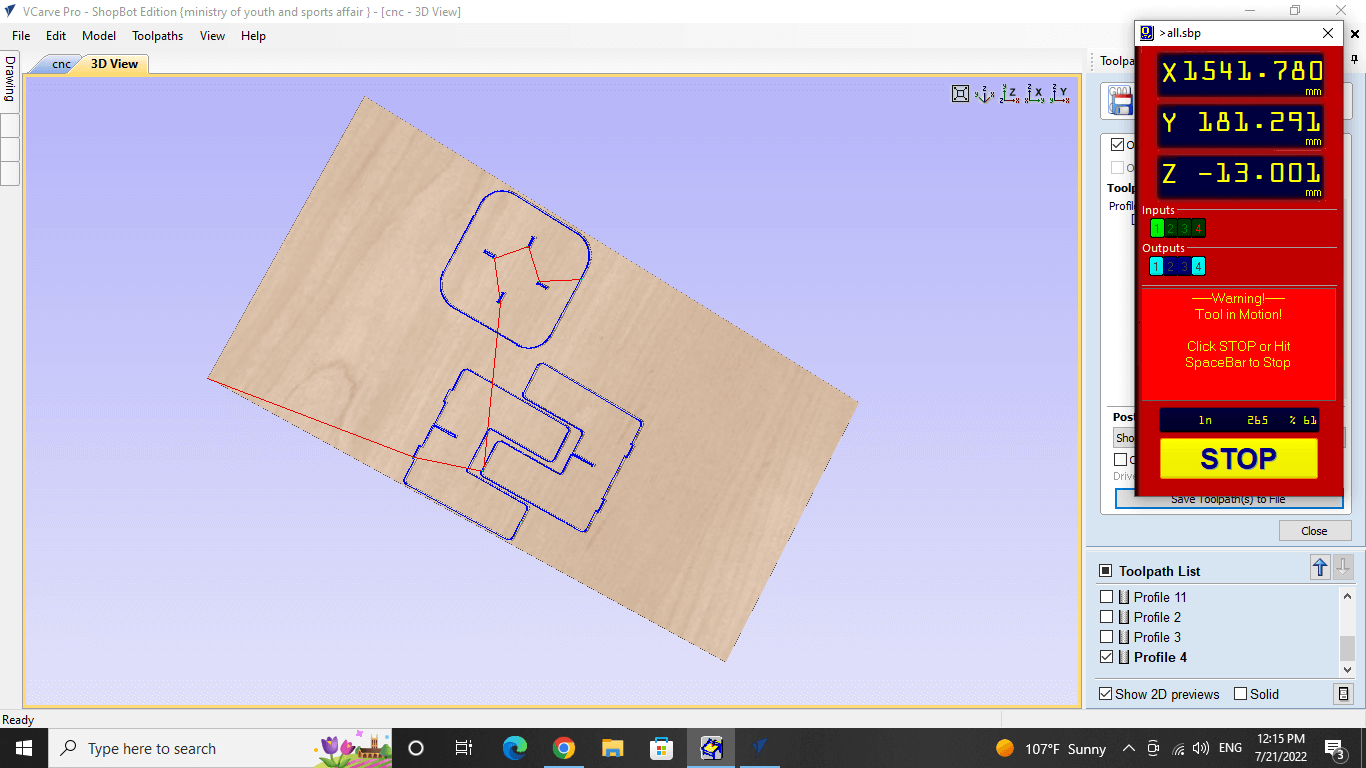
We used the shopbot machine to test the runout, alignment, speeds, feeds, and toolpaths. click here
Individual assignment
This week was a little difficult for me because it requires a lot of work, and I also had a midterm exam this week, so there was a lot of pressure. because of that I decided to go with something simple, a table. I used fusion 360.
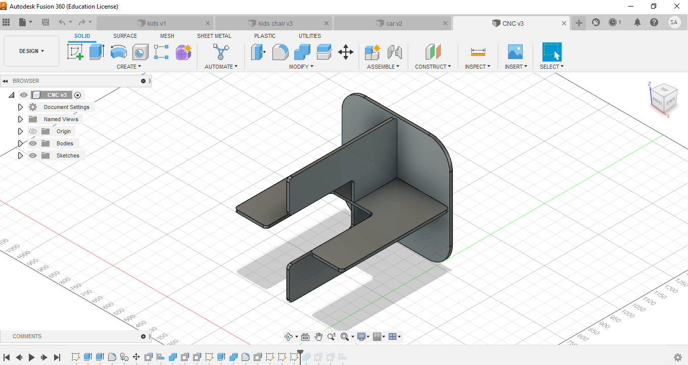
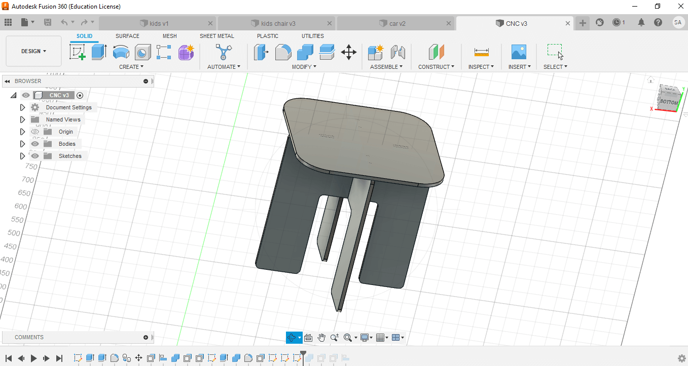
My design measures 500x485x520 mm and Joints size : 50 mm. I started by drawing each component separately in 2D. Then I started to marge the parts together after pulling each piece to make it 3D. Then I saved it as a DXF file.
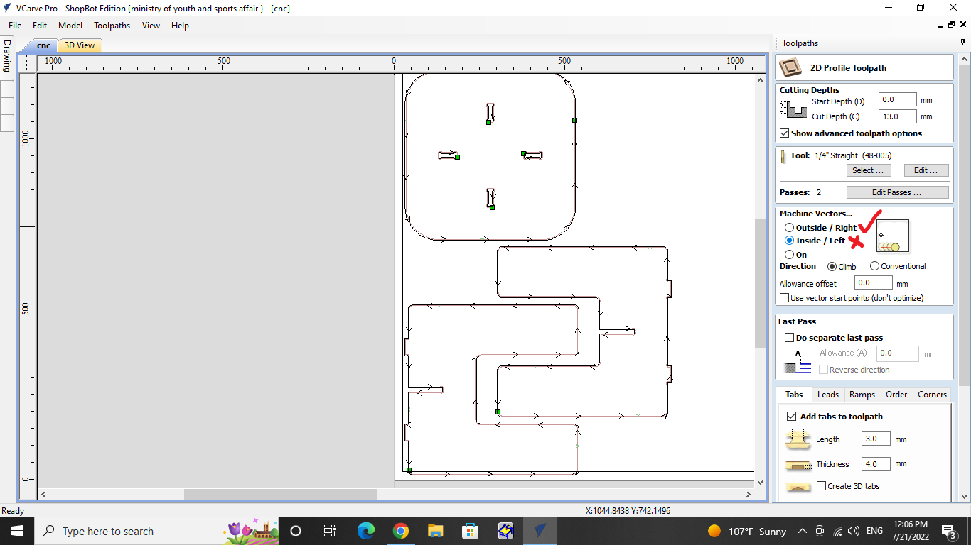
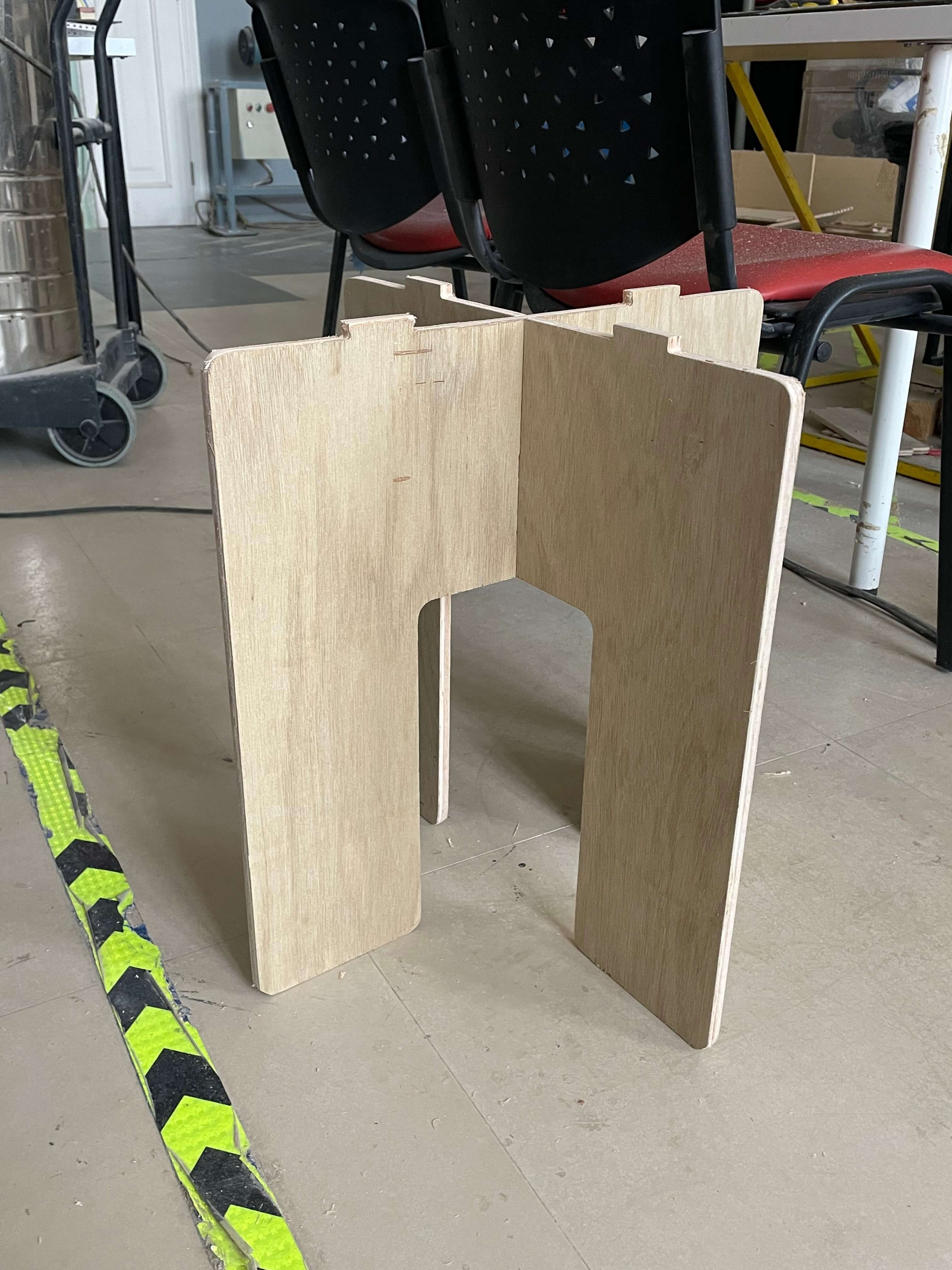
My first print went wrong because I chaos the wrong option which is to cut the joints from the inside, so I had to print it again and this is the difference as the pic shows
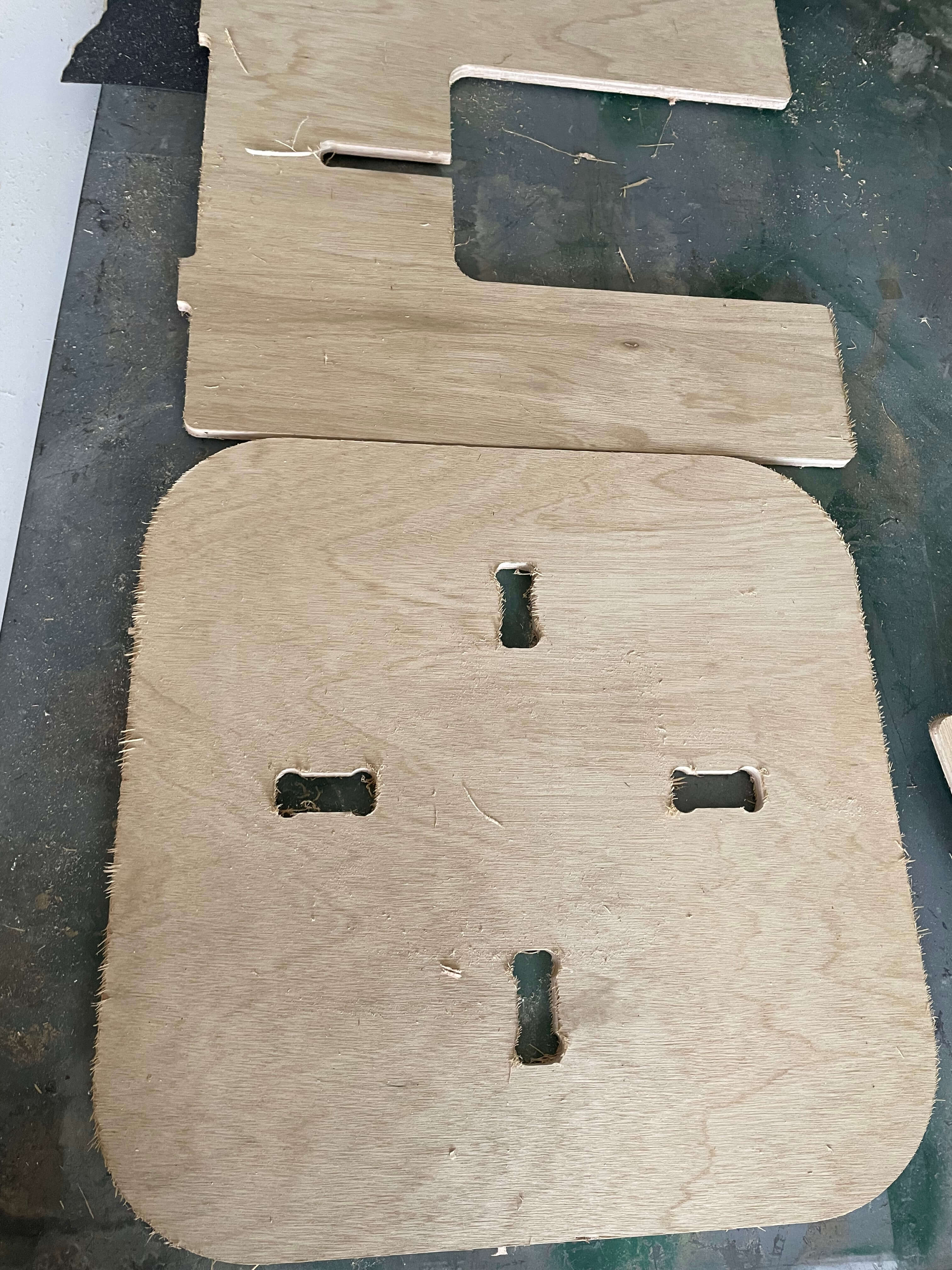
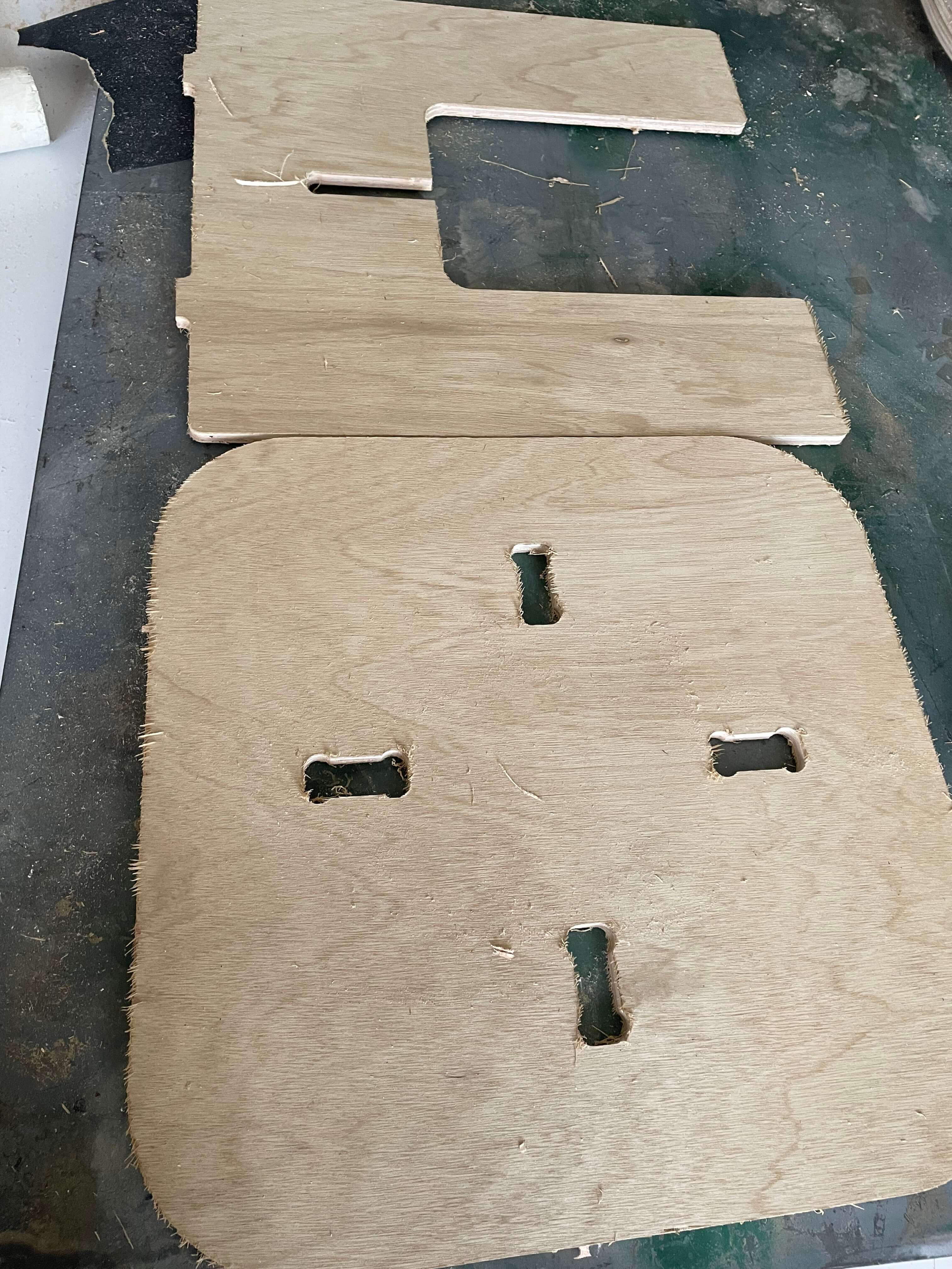 So I get back and modify it to the right setting.
After that I used the sandpaper to make it smooth.
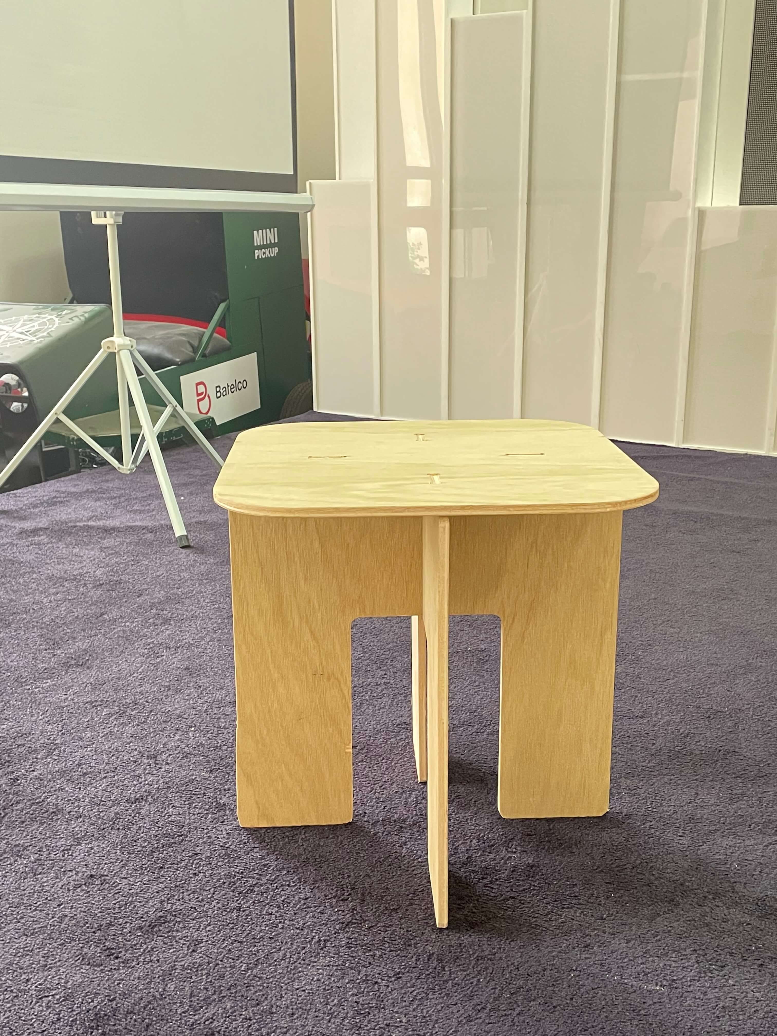
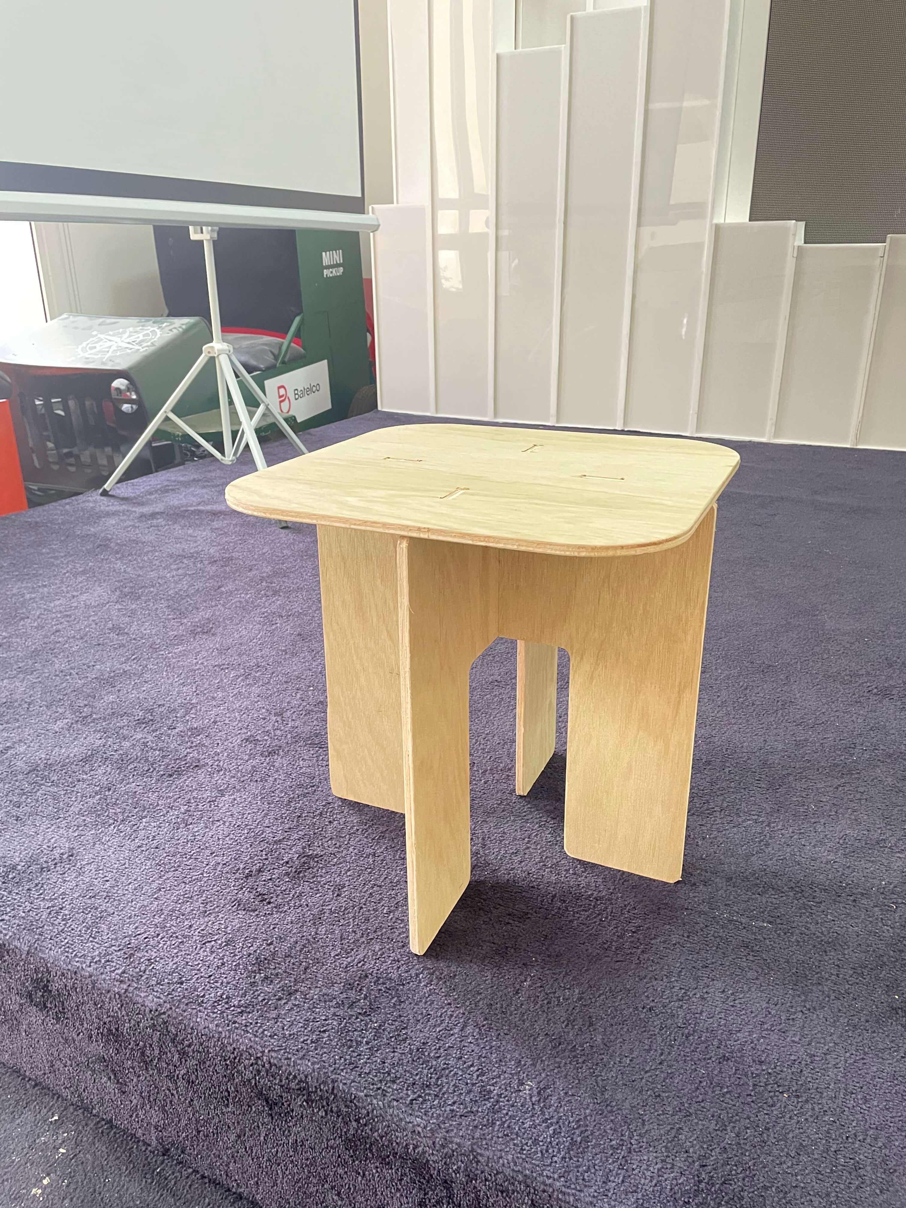 Here is the final result.
How do I feel about this week:
As I’ve already mentioned, this week was challenging for me, and I was little disappointed that I couldn’t do more. Despite this, I had a good time and feel good about what I accomplished.