2. Computer Aided design
This week I will present two 2D designs and two #d designs using different software and illustrate the construction procedure.
1- 2D designs
First of all, Cuttle and photoshop were used in order to make two 2D designs which were illustrated comprehensively.
1- Cuttle
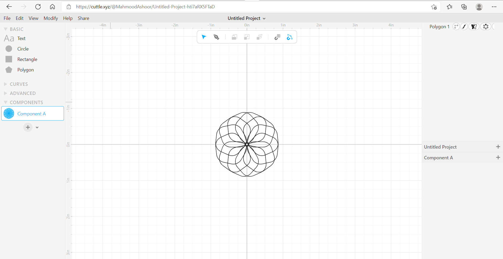
Cuttle is a useful software for simple 2D designs that uses vectors to assemble the design which yields in not affecting the quality of the design while zooming as it is going to be scaled. It will be used to design a shape that is mainly used for decoration which can be seen several occasions like Eid.
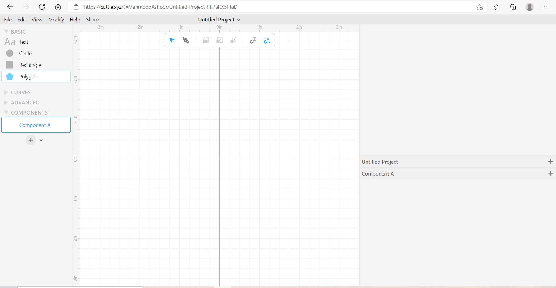
First of all, after choosing to do a new project, the following site will appear:
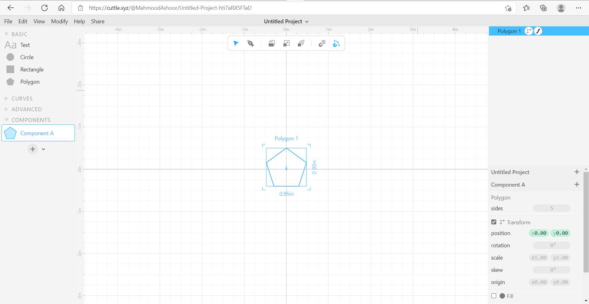
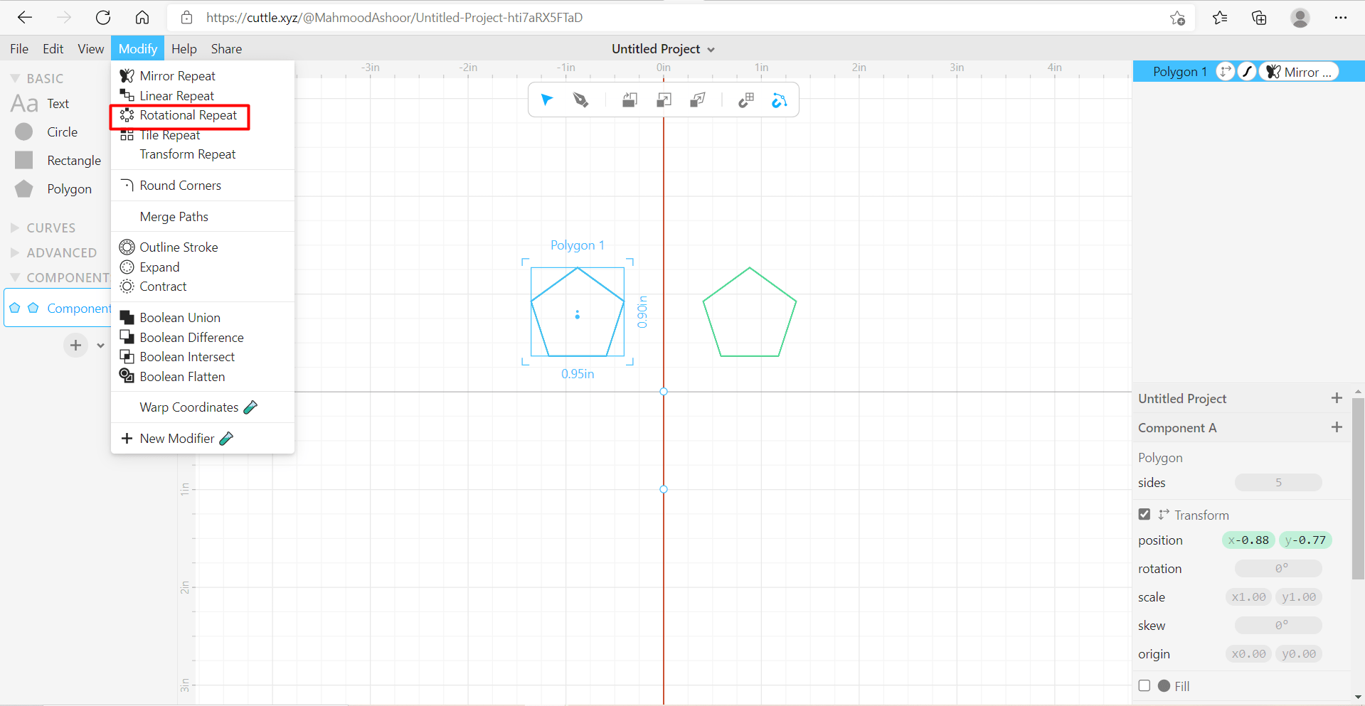
Then, the polygon shape will appear as follows:
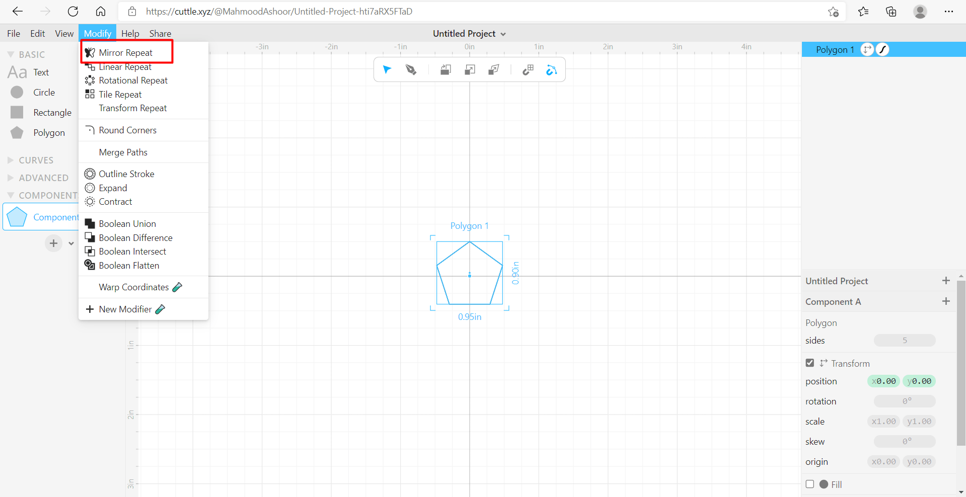
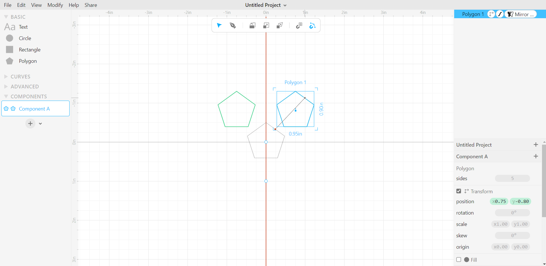
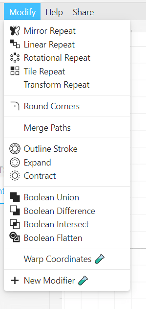
Choose modify and then repeat in order to mirror the polygon:
After mirroring the polygon, choose from the modify section to rotationally repeat the polygon which would yield to the following:
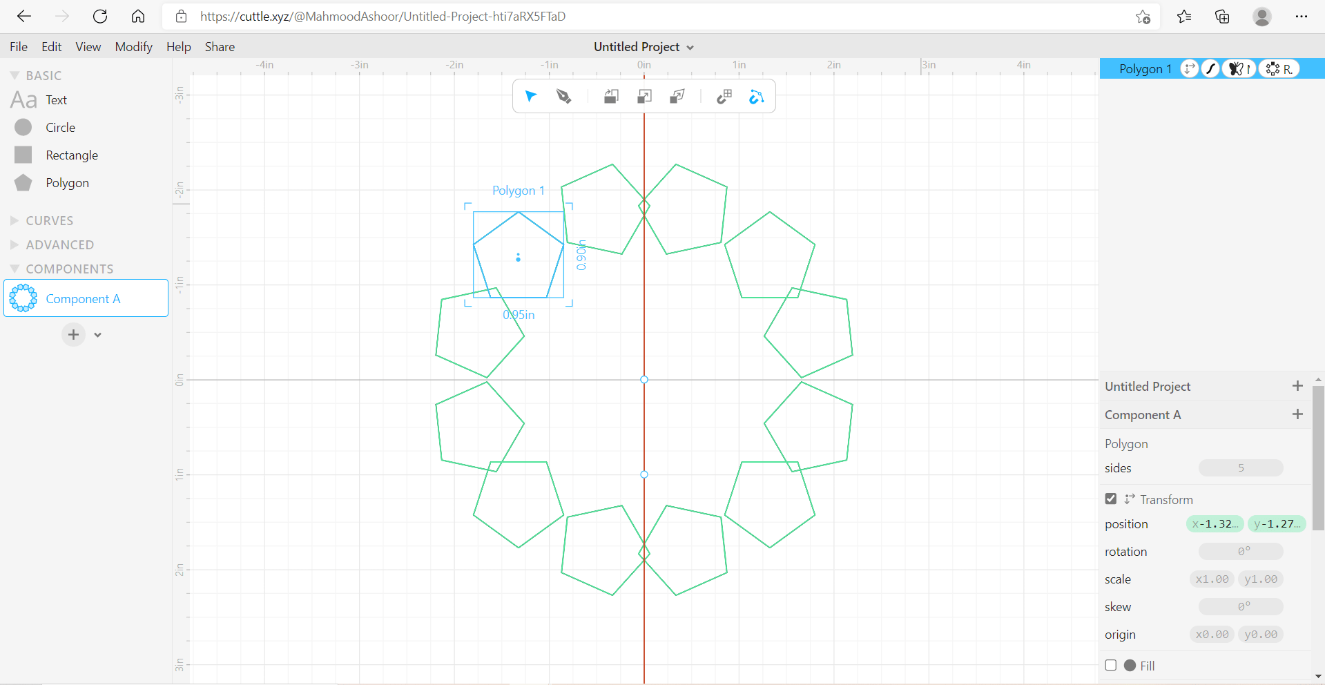
After repeating, drag the polygon sequence to inside until they all meet together:
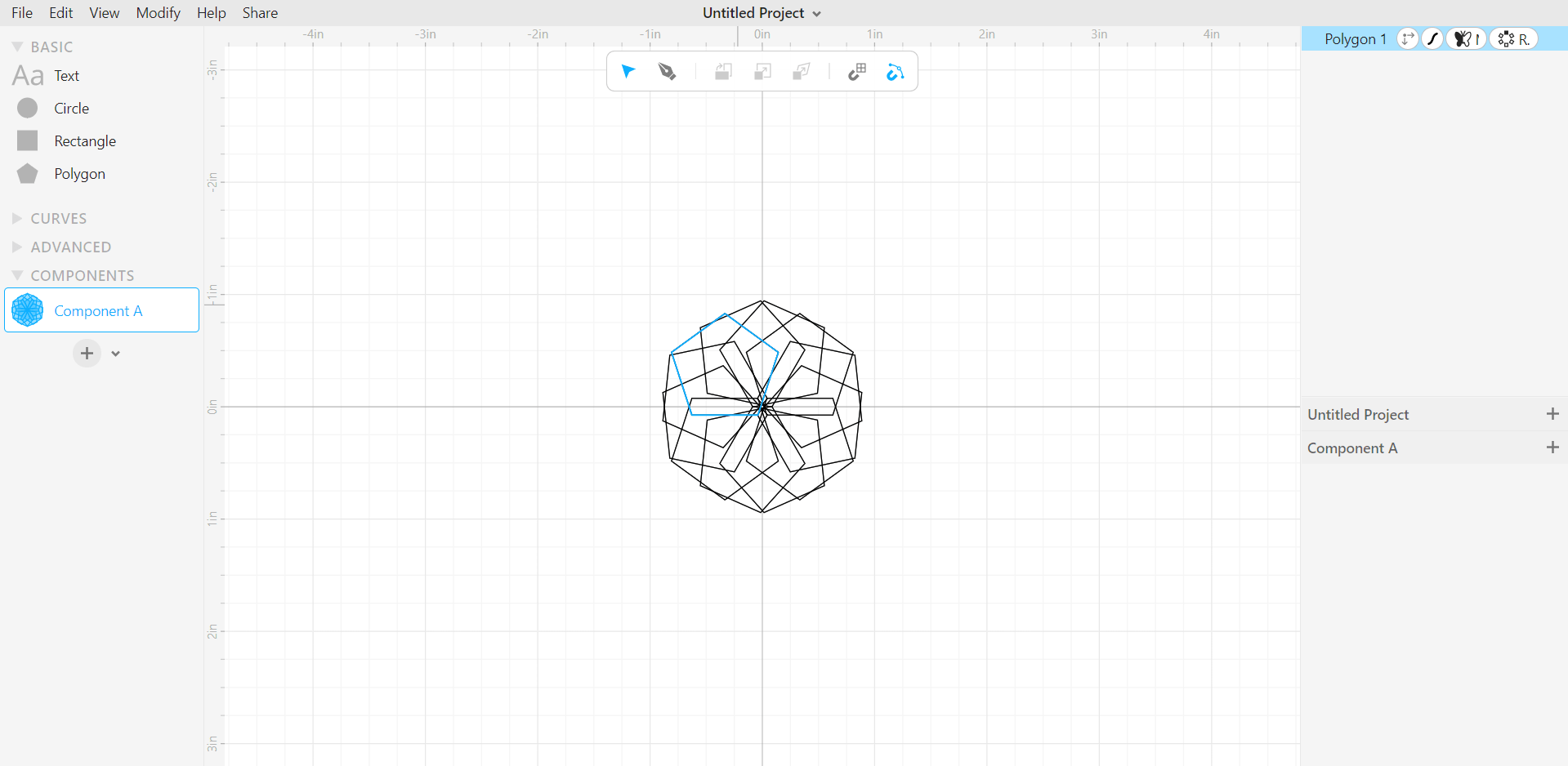
Then, from the modify section, round the corners which would yield in the final design which is illustrated in the final picture:
2- Photoshop
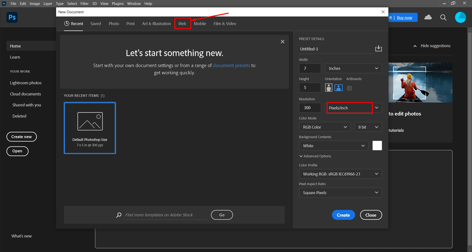
Photoshop is program that utilizes pixels to demonstrate the anticipated design which here was utilized to show the famous quote of Dr Shaker Haji in the chemical reaction engineering course.
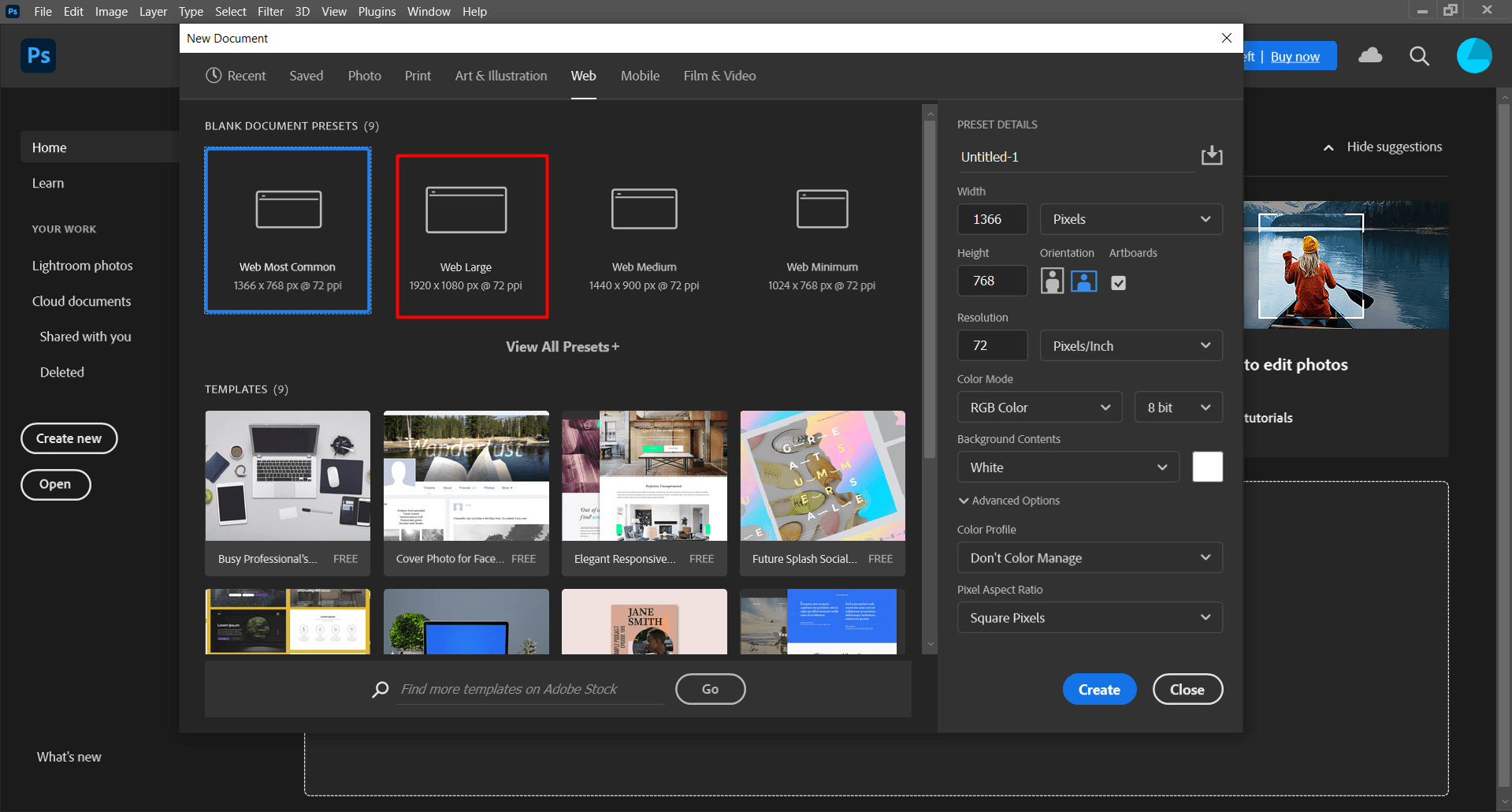
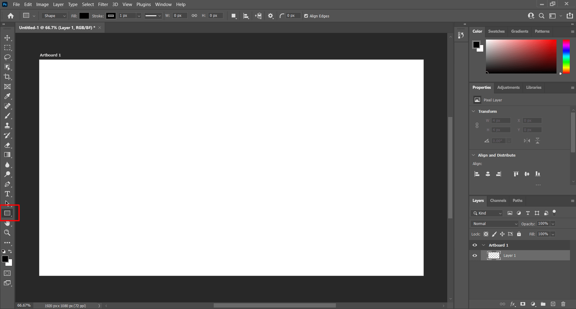
After Launching Photoshop and creating a new file, it can be seen that the photoshop uses pixels. After pressing the web section, select it to be 1920 x 1080 as illustrated:
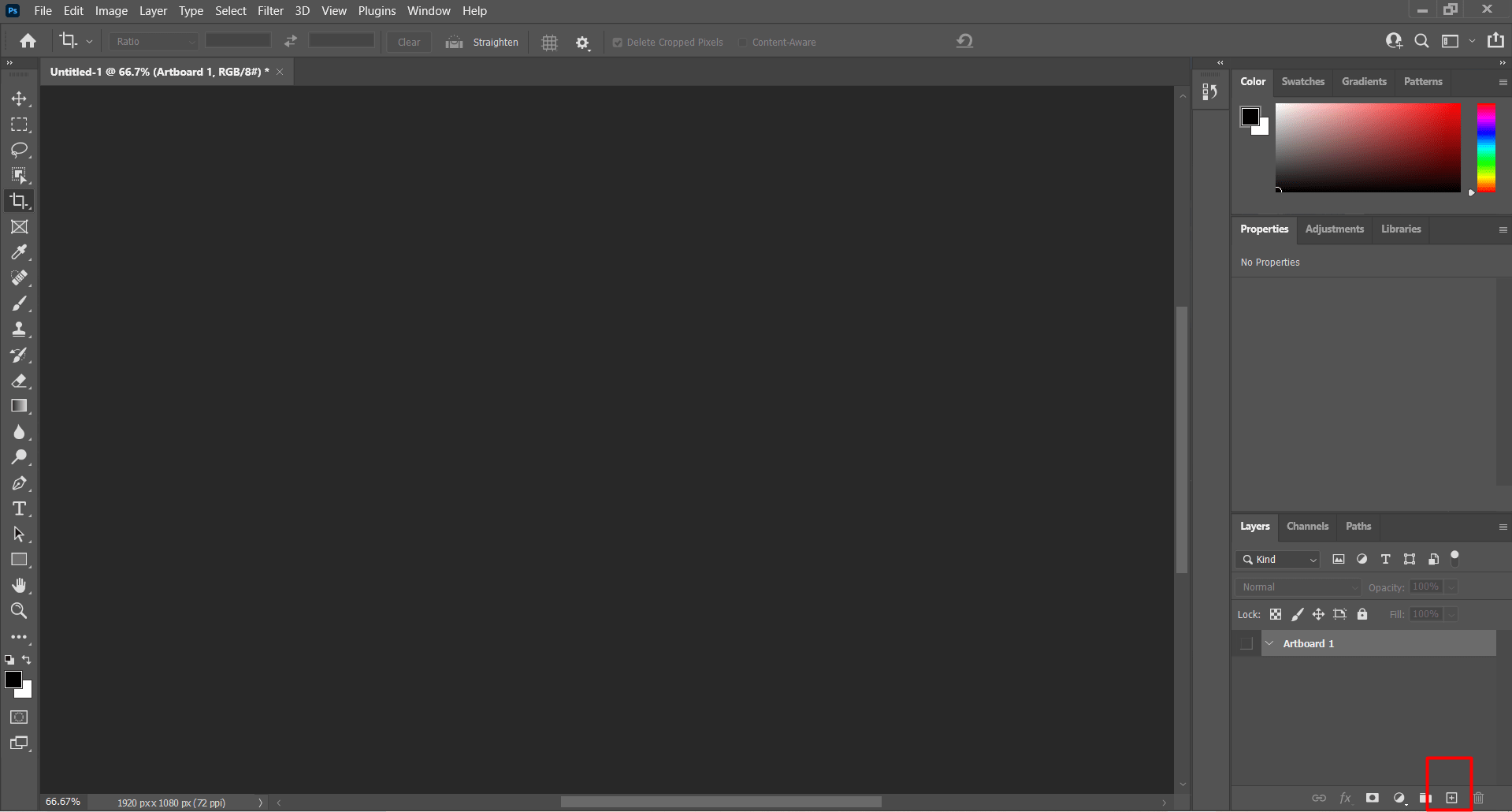
Then, this window will appear, press the highlighted icon to create a new layer:
This icon will permit the choice of the boundary of the design:
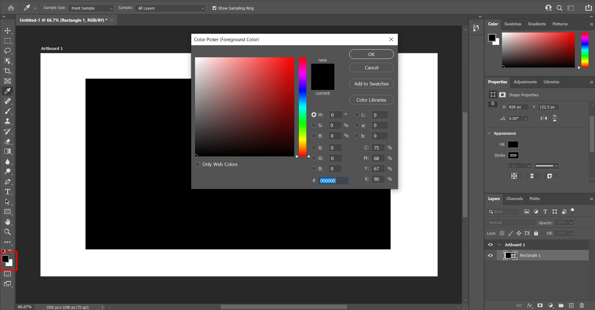
The highlighted option was used to modify the background color of the design which was changed to grey:
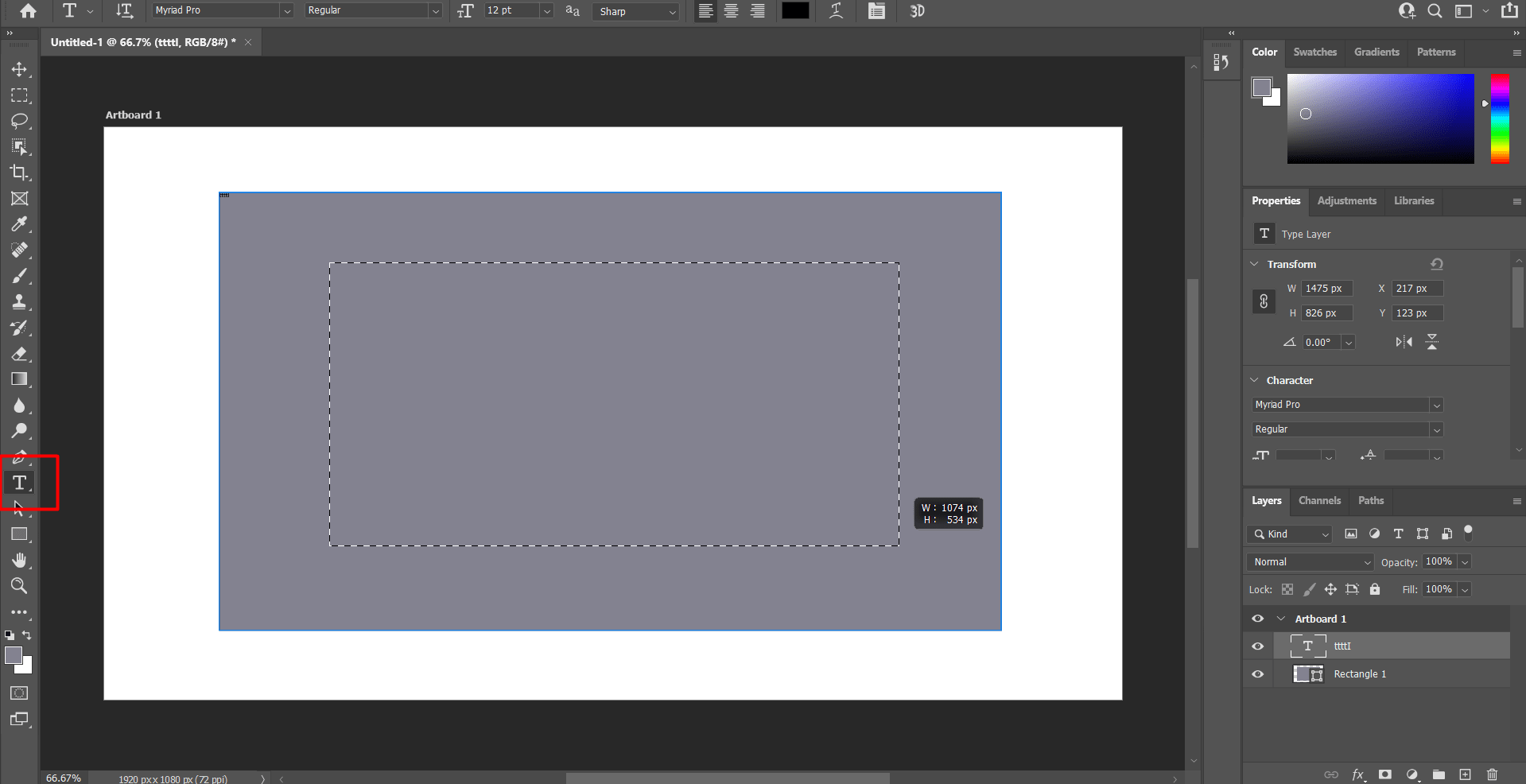
After that, this is done to generate the text box which would be used to write the quote:
This box is used the change the text color:
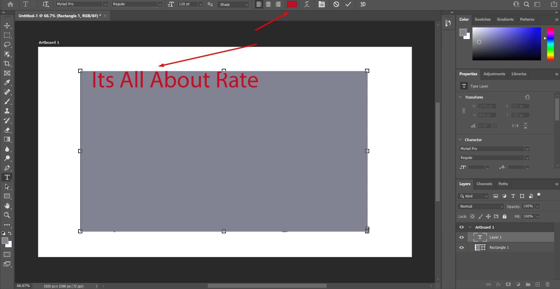
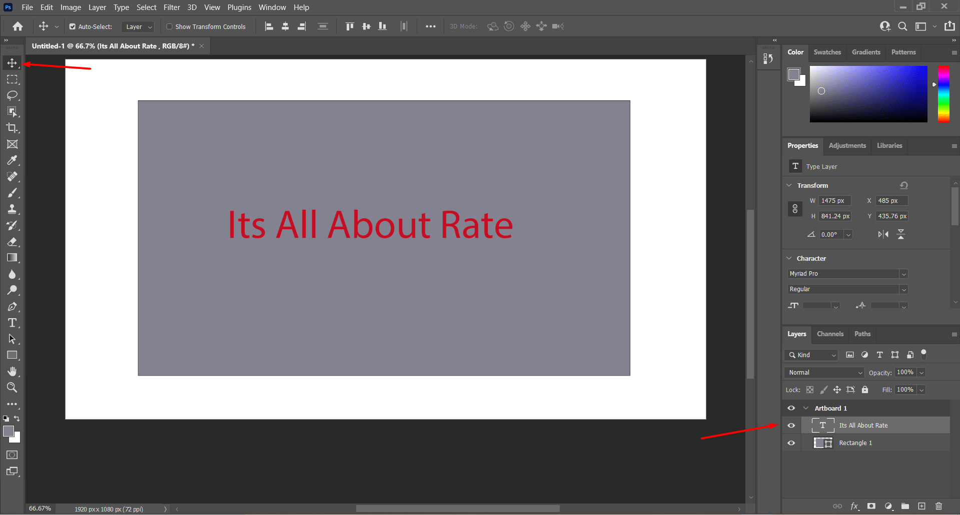
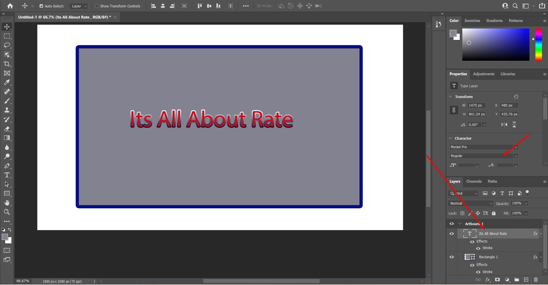
The following picture illustrates how the text is moved, after choosing the icon the text box generated is marked and the text is moved by dragging it with the mouse:
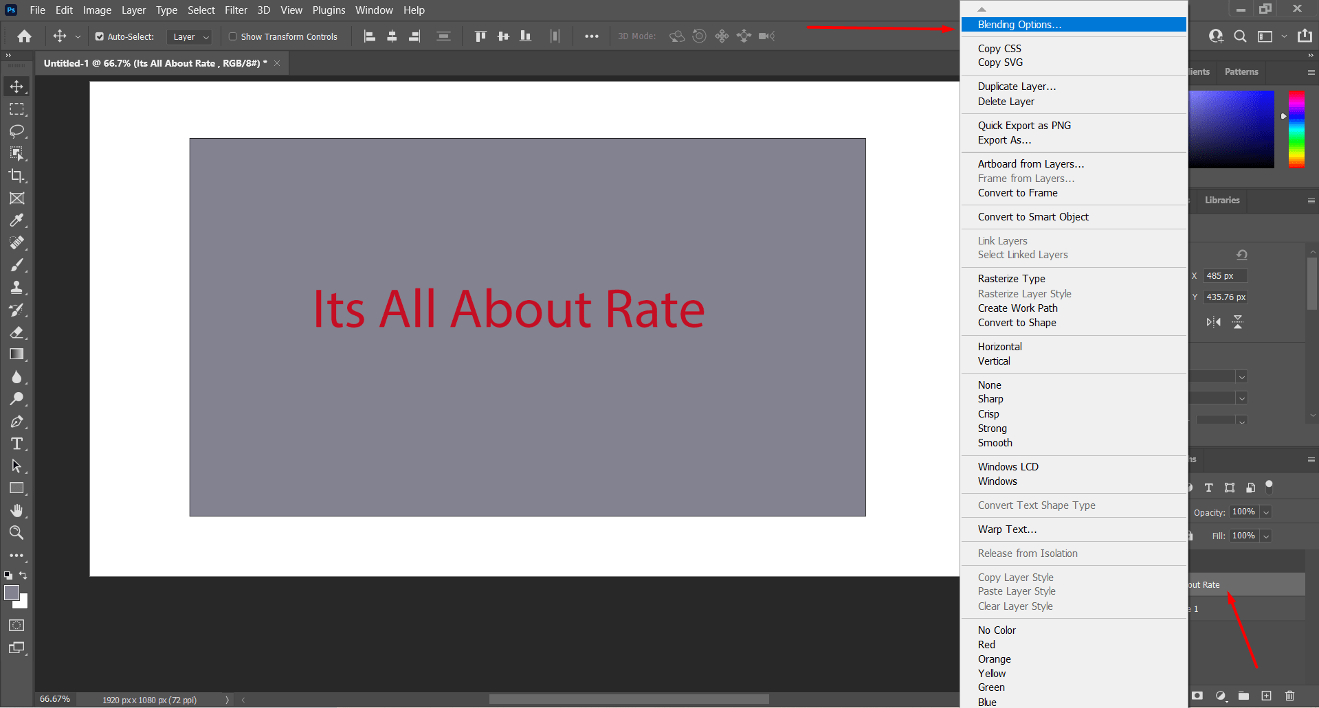
The text is adjusted by right clicking on the text box from the layers section, then choosing the blending option. This will show the window at which you can adjust the settings to get the design you want.
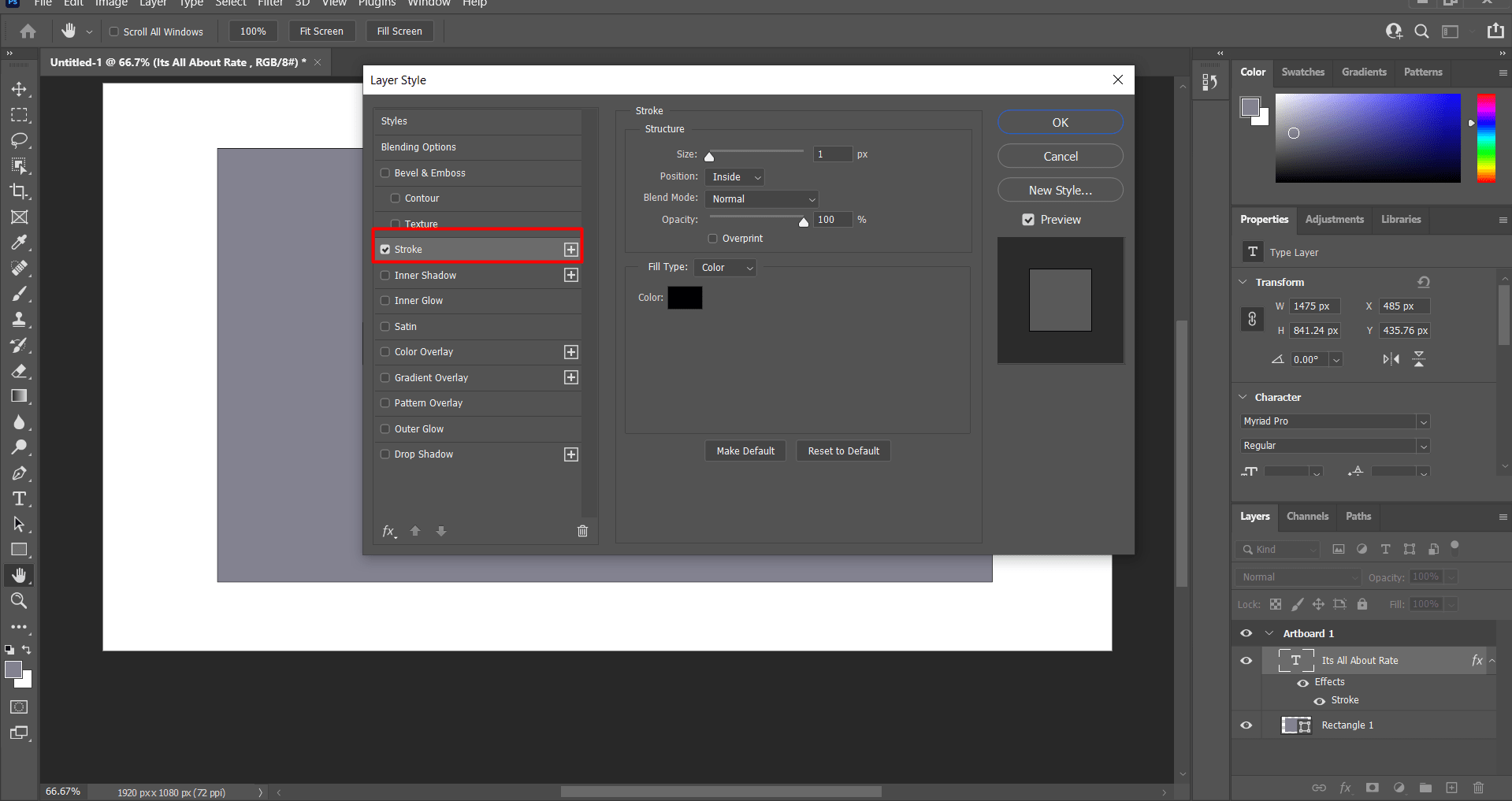
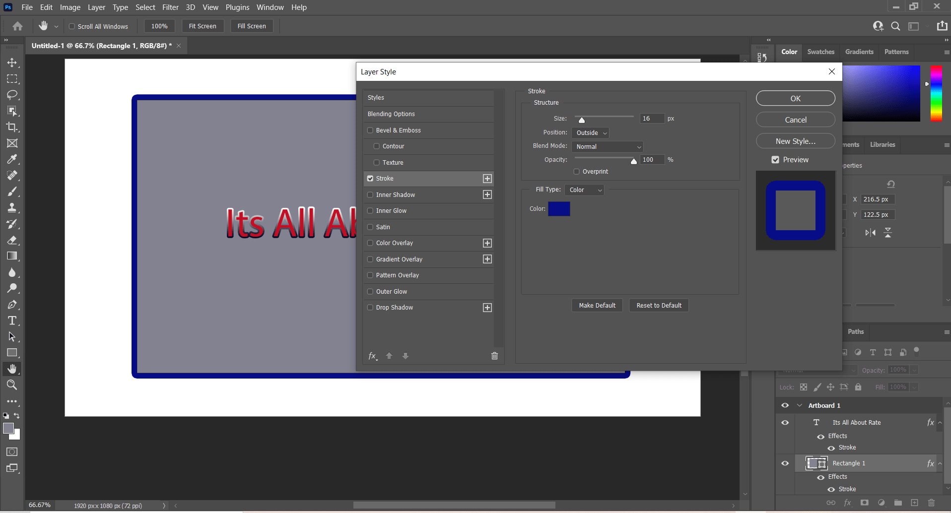
Same thing could be applied to the design box (i.e. the layer):
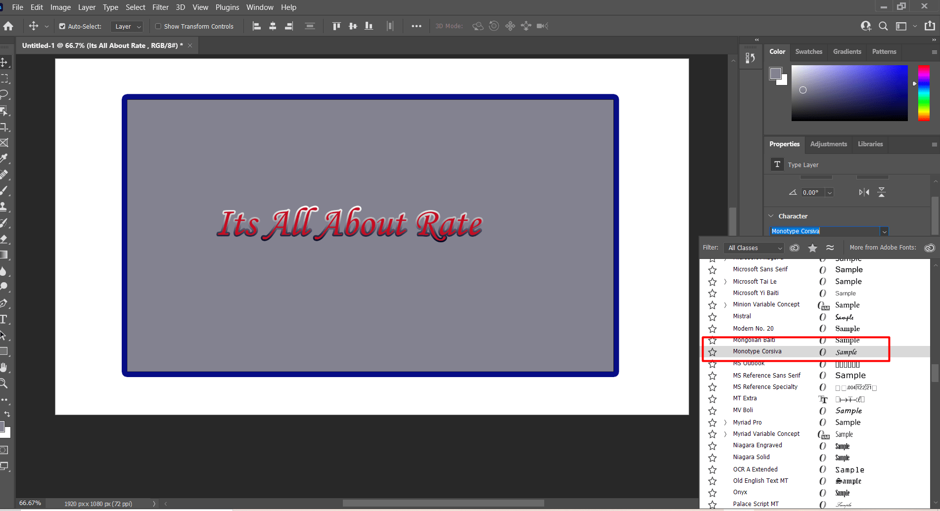
This can be done to change the font of the text:
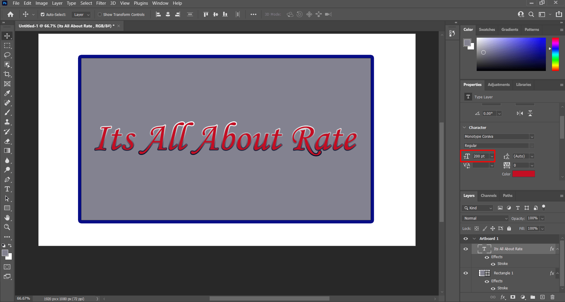
Here, the text size can be adjusted to be adequate to the frame:
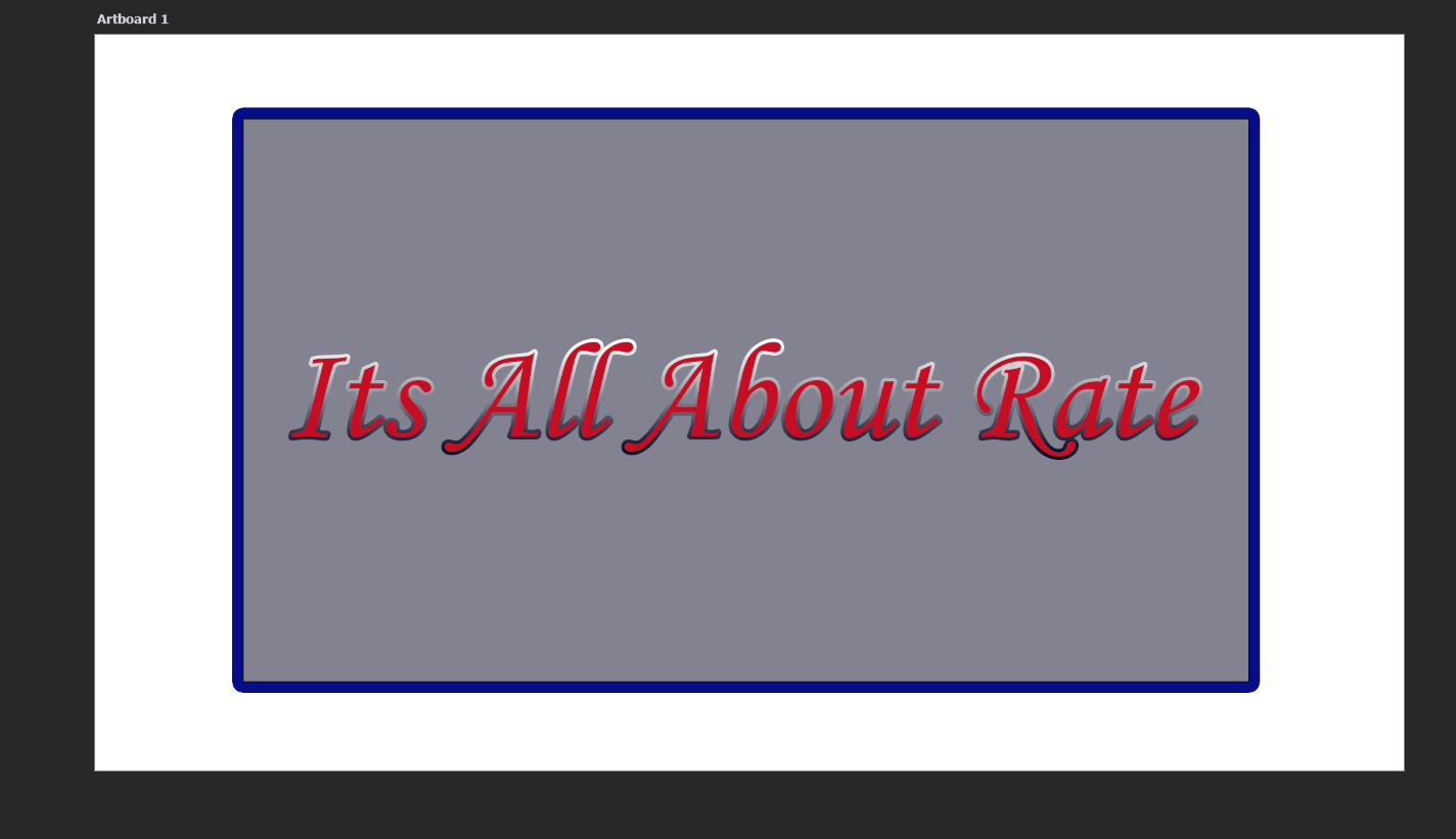
A picture of the final design.
2- 3D designs
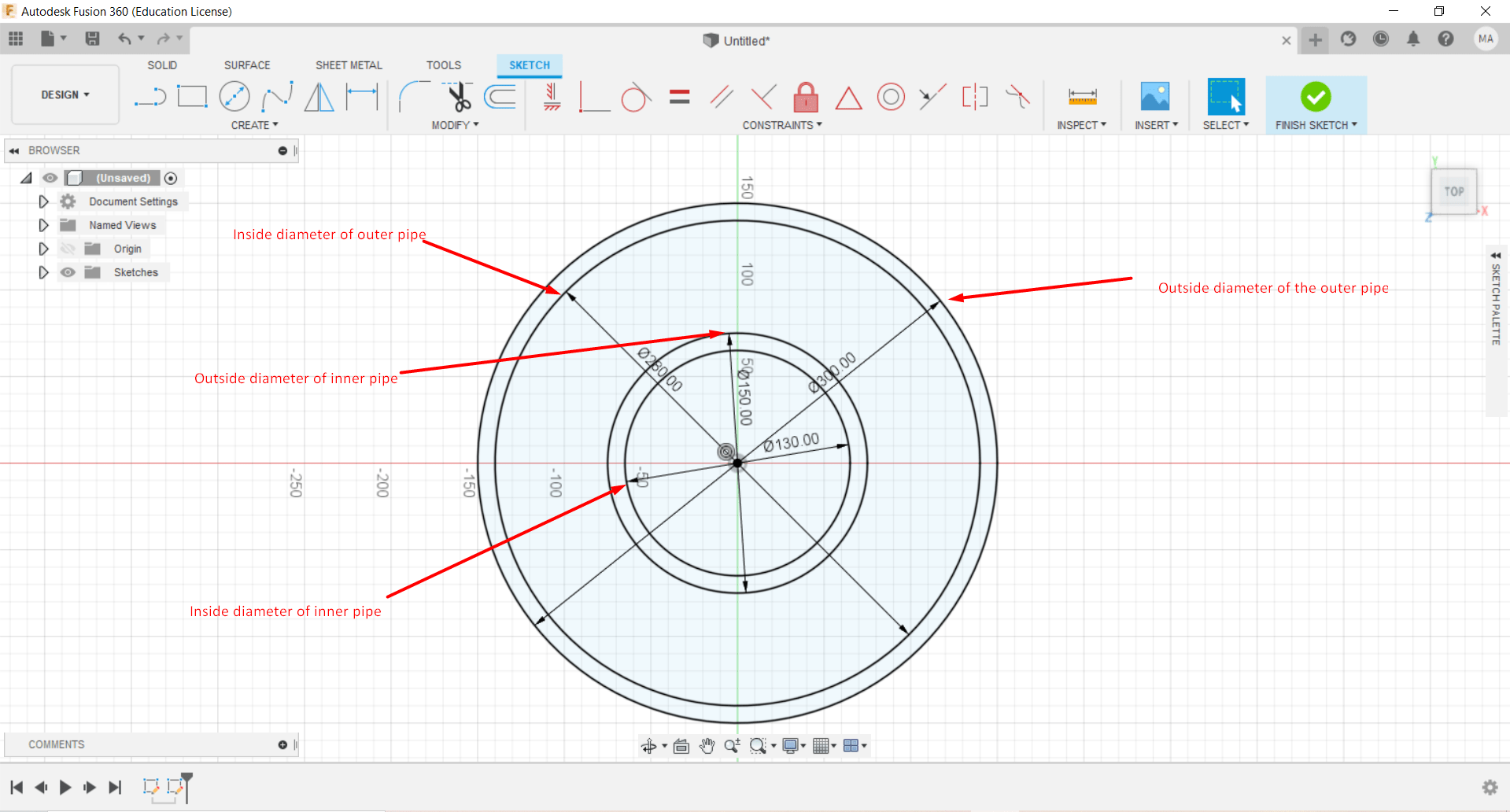
3D designs were mainly constructed using Fusion 360 and openscad software to design a double pipe heat exchanger for utility purposes. The dimensions were the same for both double pipe heat exchanger model (i.e. both openscad and Fusion 360 have the same dimensions).Thickness of both inner and outer pipe were set to be 10mm, the diameter of the inner and outer pipe were set to be 130mm and 280mm respectively. The length is one meter.
1- Fusion 360
Fusion 360 is the first software to be utilized to design the double pipe heat exchanger equipment which is utilized for utility purposes.
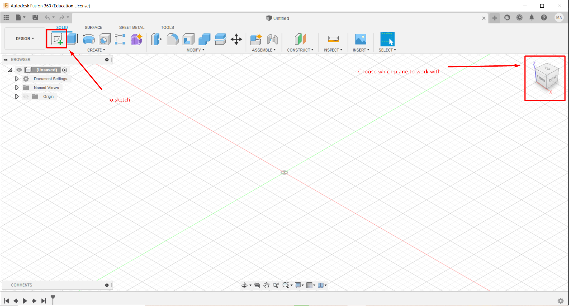
First, after opening an new folder in Fusion 360, this page will appear, where you can select a new sketch to work on in order to start you design. The right block can be utilized to adjust the view angle at which you will design:
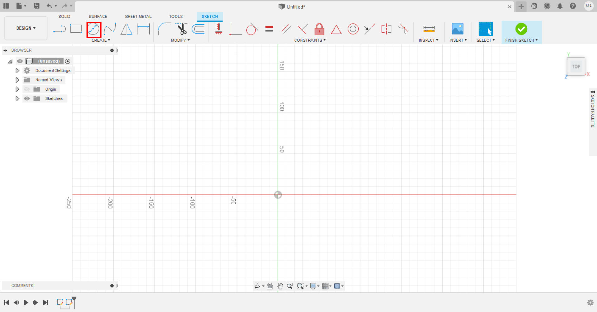
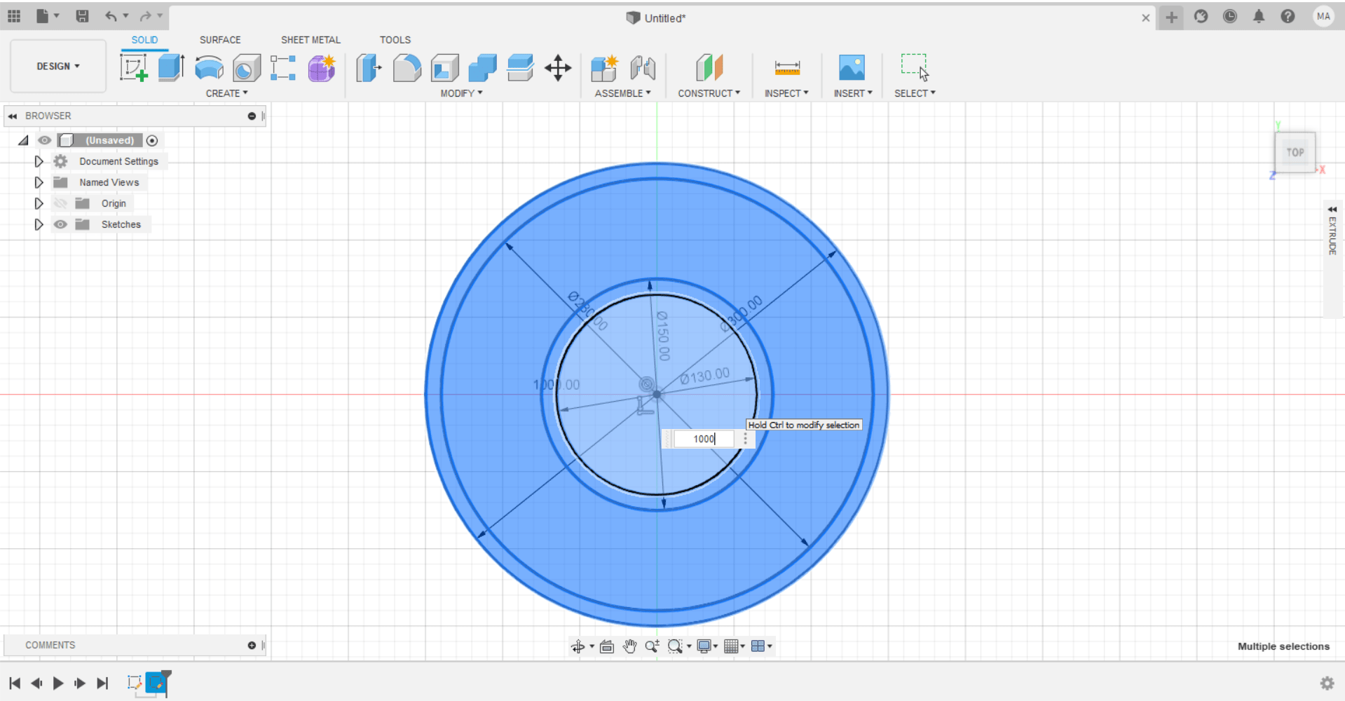
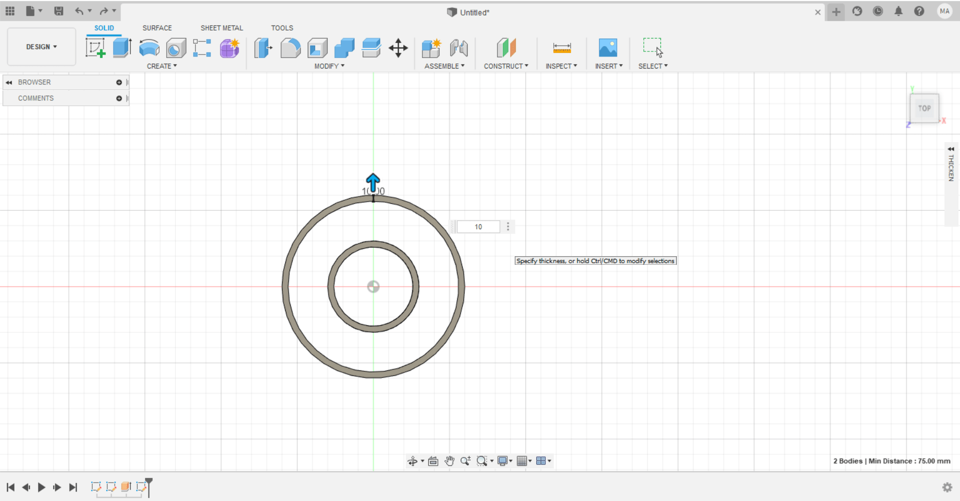
Select the circle option and adjust the dimensions as per illustrated previously:
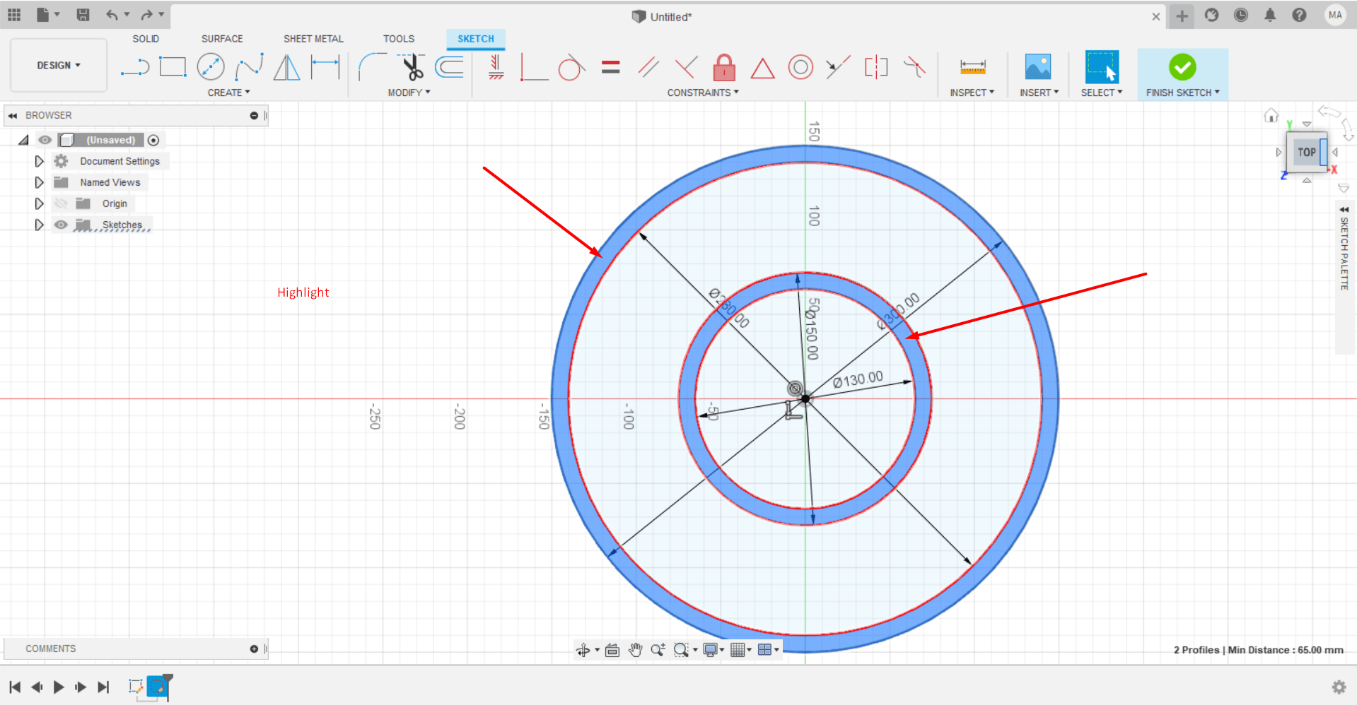
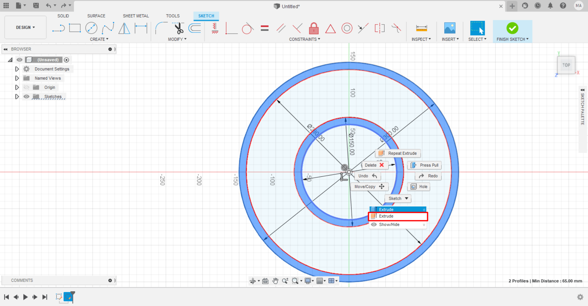
Then, select the illustrated sections and select the extrude option to longitude the circle into a cylindrical shape:
After successfully extruding the design, it will look like this:
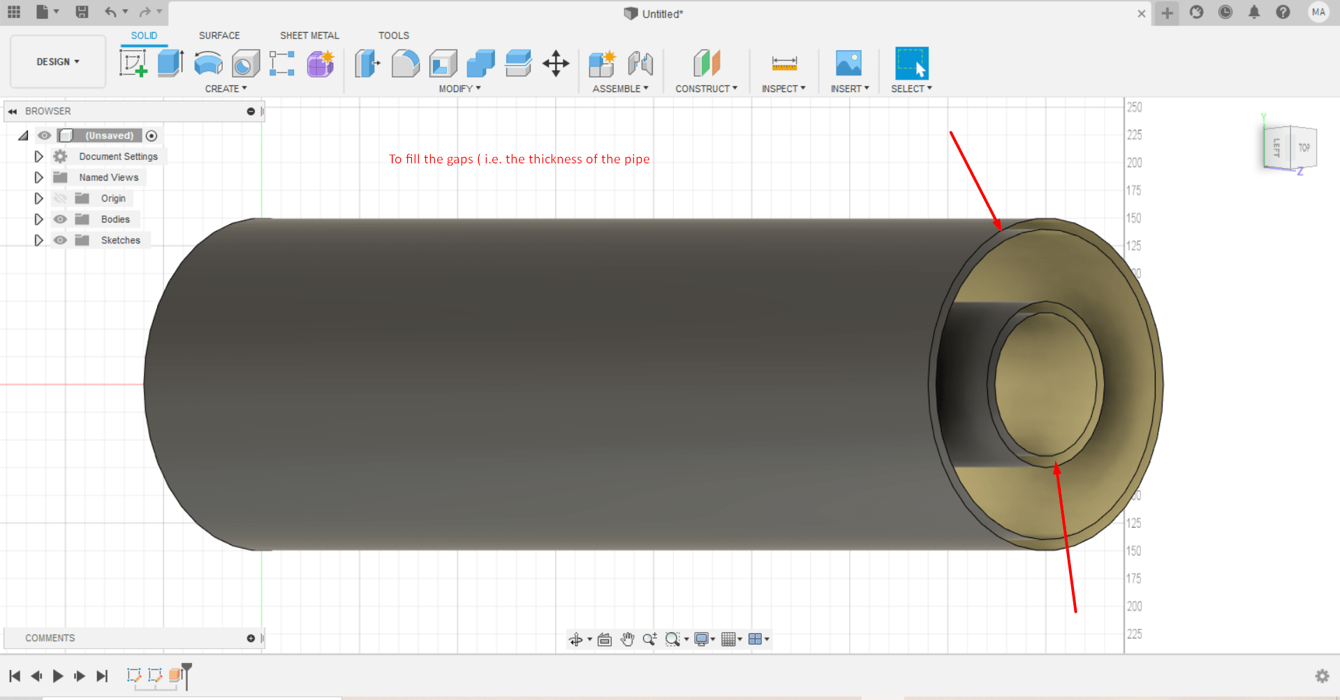
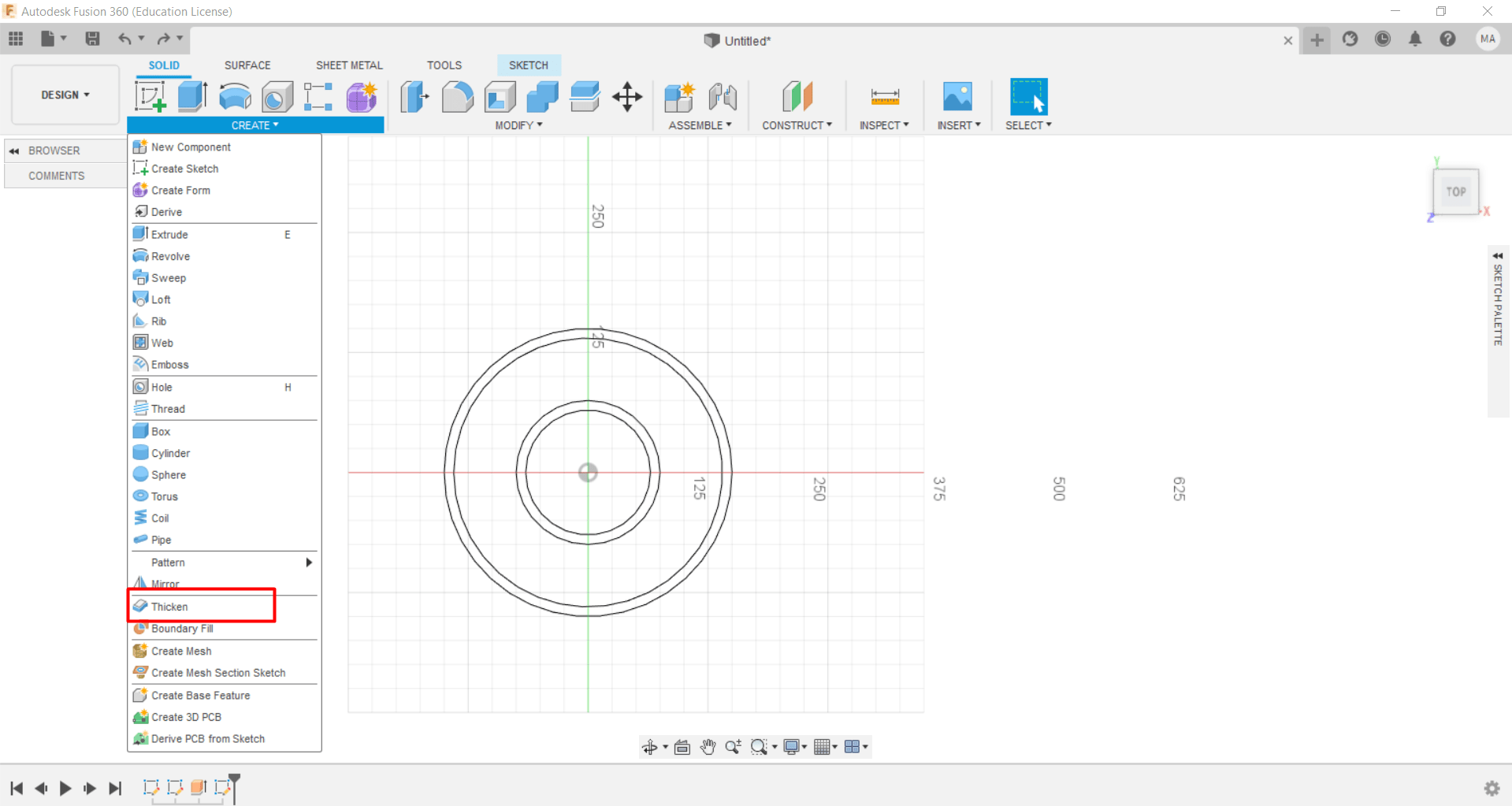
To account for the thickness of the pipe, choose the create section and then the thickness option, then highlight the inner diameter of both inner and outer pipe and set the required thickness:
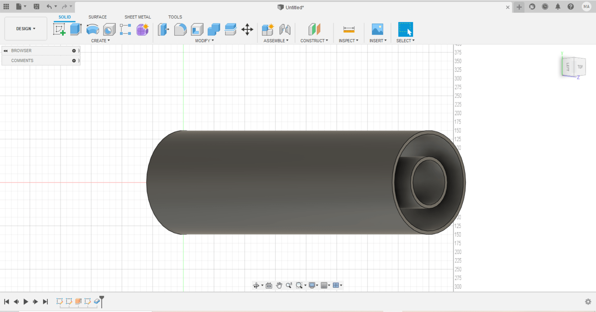
The final design of the double pipe heat exchanger will look as follows:
2- Openscad
Openscad is utilized to design and model the double pipe heat exchanger based on several codes used to demonstrate the required design.
Fisrt of all, the $fn commaned was used in order to ensure the cylindrical shapes to be well rounded by putting a high number with this command.
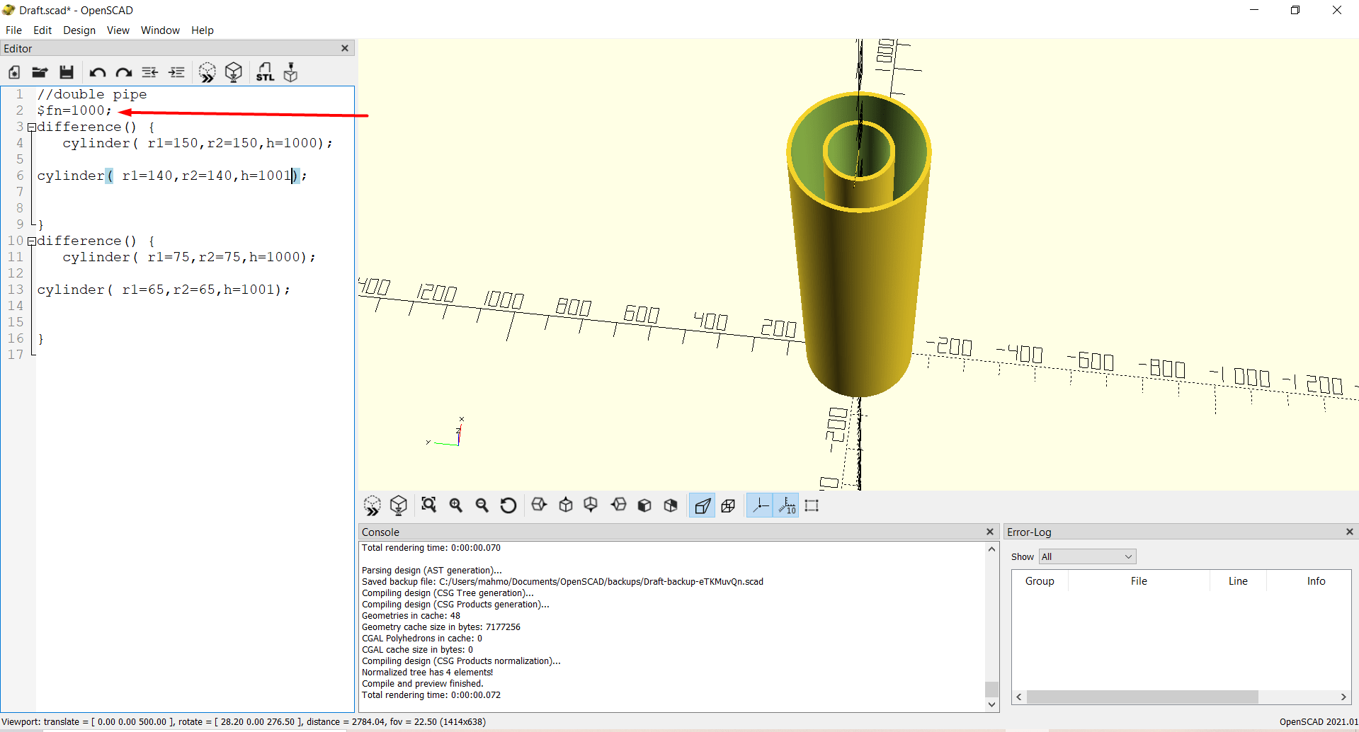
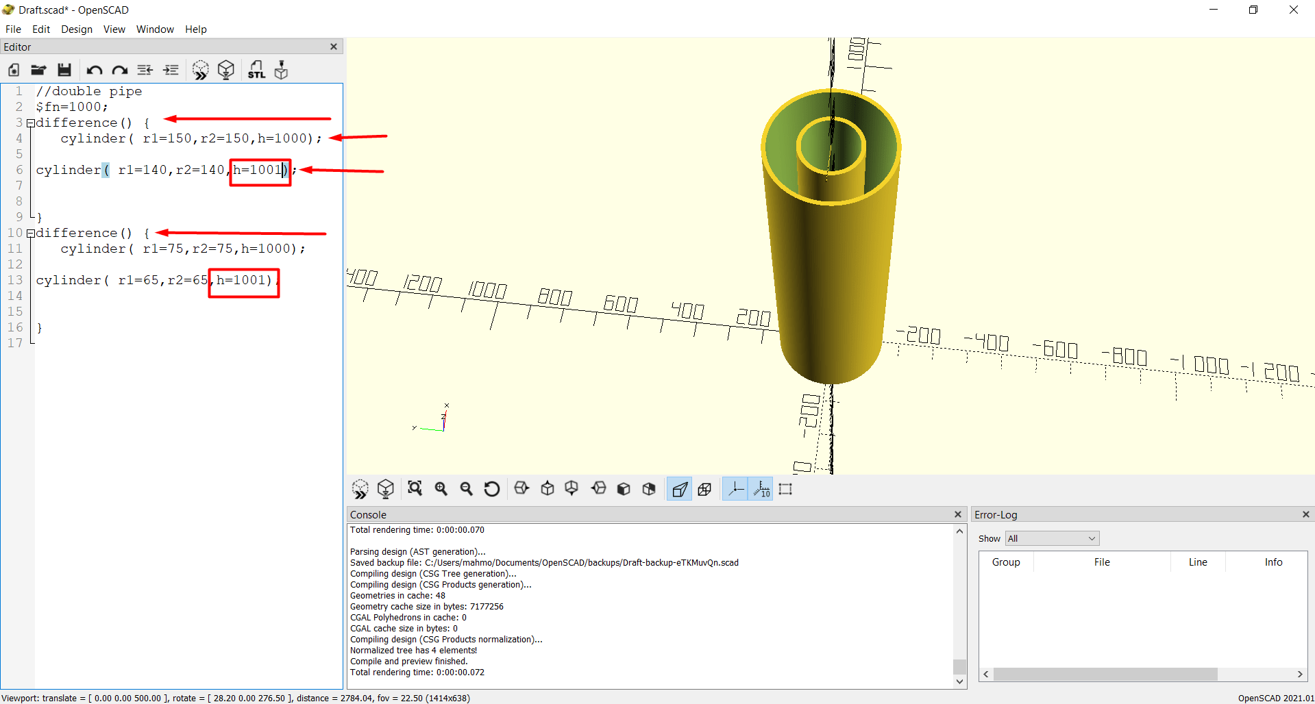
After further investigation and studying, the difference command was utilized to implement the double pipe heat exchanger successfully, the difference command works on the following principle: it subtracts the below function from the above function and displays the remainder (i.e. displays the areas where both commands do not intersect only and the intersection become hollow). This is done for both the inner and outer pipe. Also, the height for the second command is adjusted to be slightly higher to avoid any errors in the model:
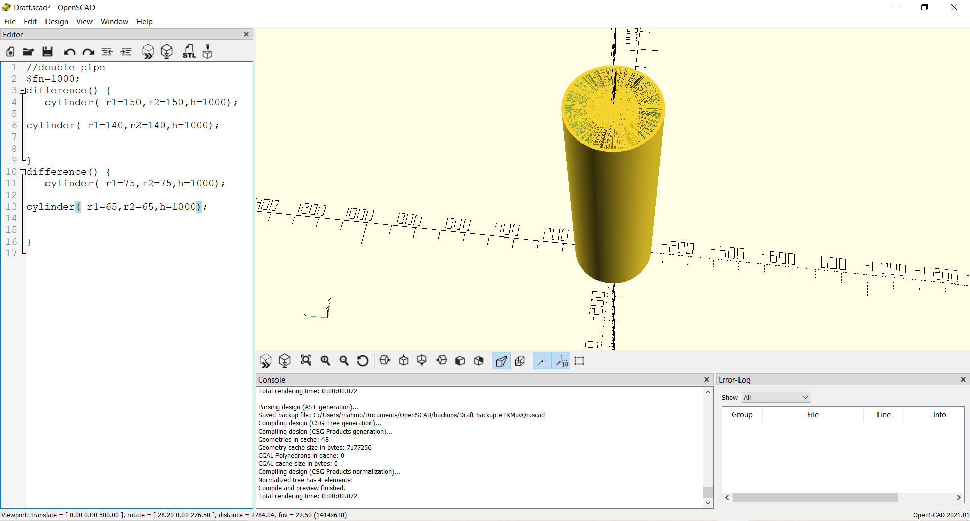
This is the error which is avoided by the aforementioned adjustment
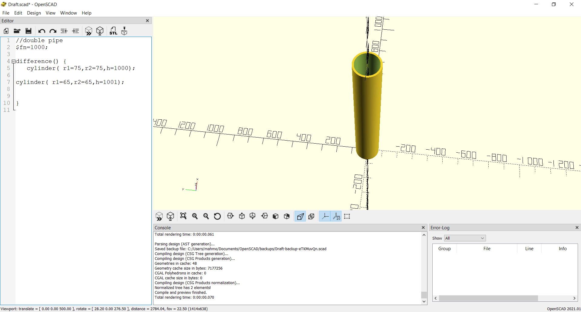
This is a picture showing the inner pipe only and its corresponding function:
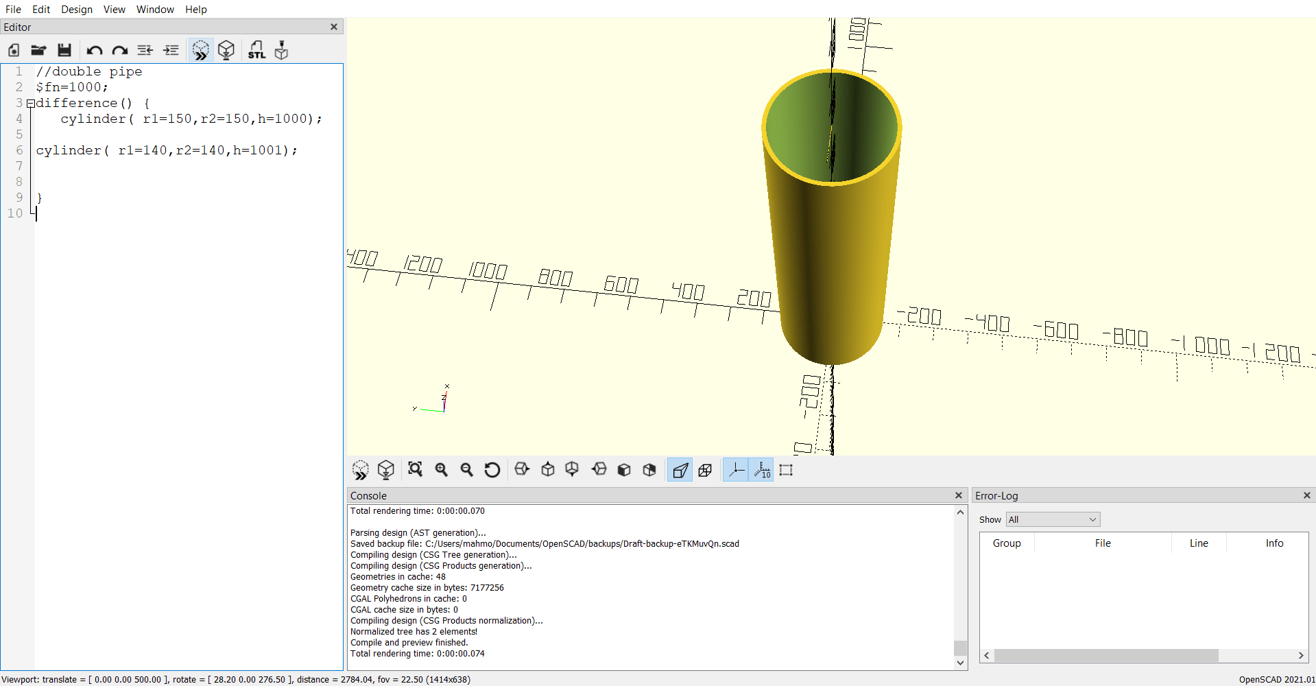
This is a picture showing the outer pipe only and its corresponding function:
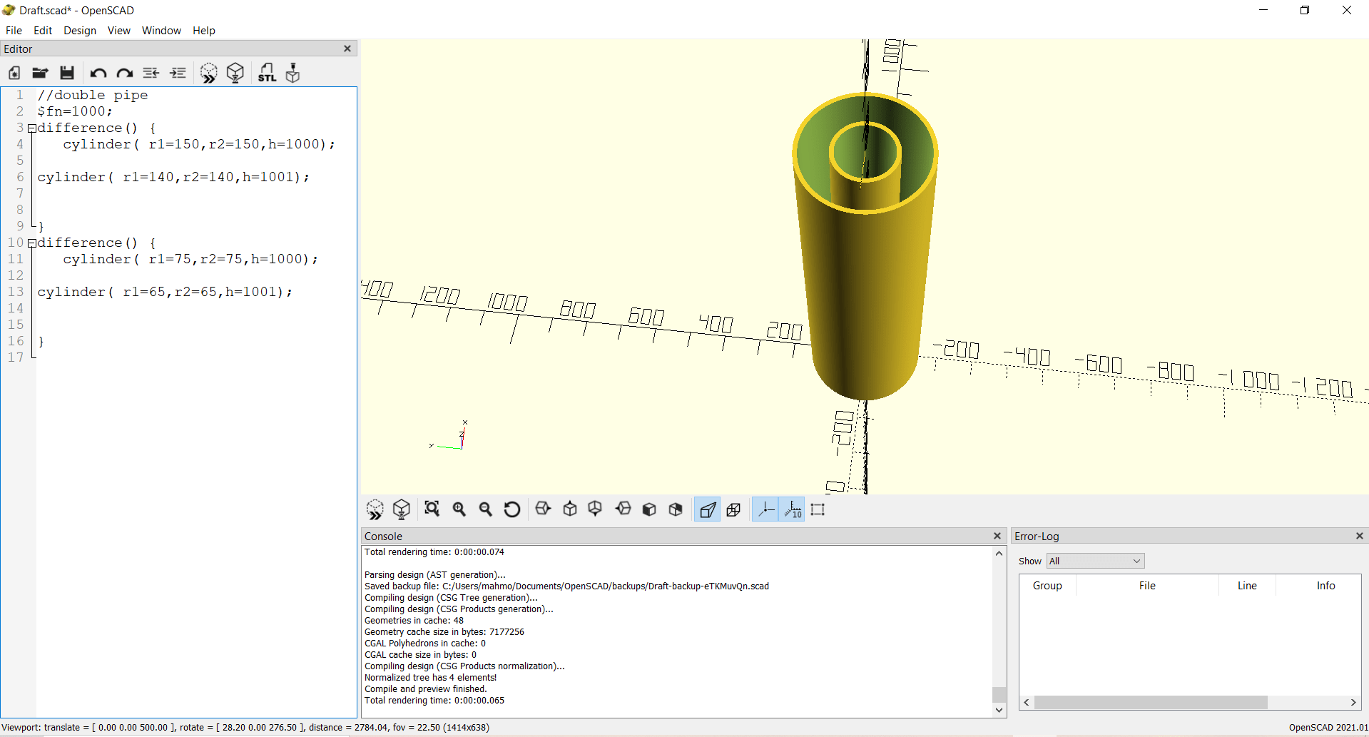
The final design is as shown below: