5. Computer-Controlled Cutting
This week I will be discussing the designs made for both the CO2 laser cutter and the vinyl cutter. Plus, the experience I went through setting up both machines and what I encountered while working on them.
Group Assignment:
Link: Group assignment
CO2 Laser Cutter:
The CO2 laser cutter machine works on the principle of accumulating the beam intensity inside a confined chamber that has two mirrors on both ends, one is fully reflective, and the other is partially (meaning that some of the light will go through and some will reflect in the chamber), resulting in the intensity accumulation inside the chamber. The CO2 laser cutter is considered as a subtractive process. The gases inside mainly consist of helium, nitrogen, and CO2. The CO2 laser design is based on vectors rather than raster which ensures the accuracy of the designs which are later incorporated to be made with the machine.
Circle and Polygon Fusion Design:
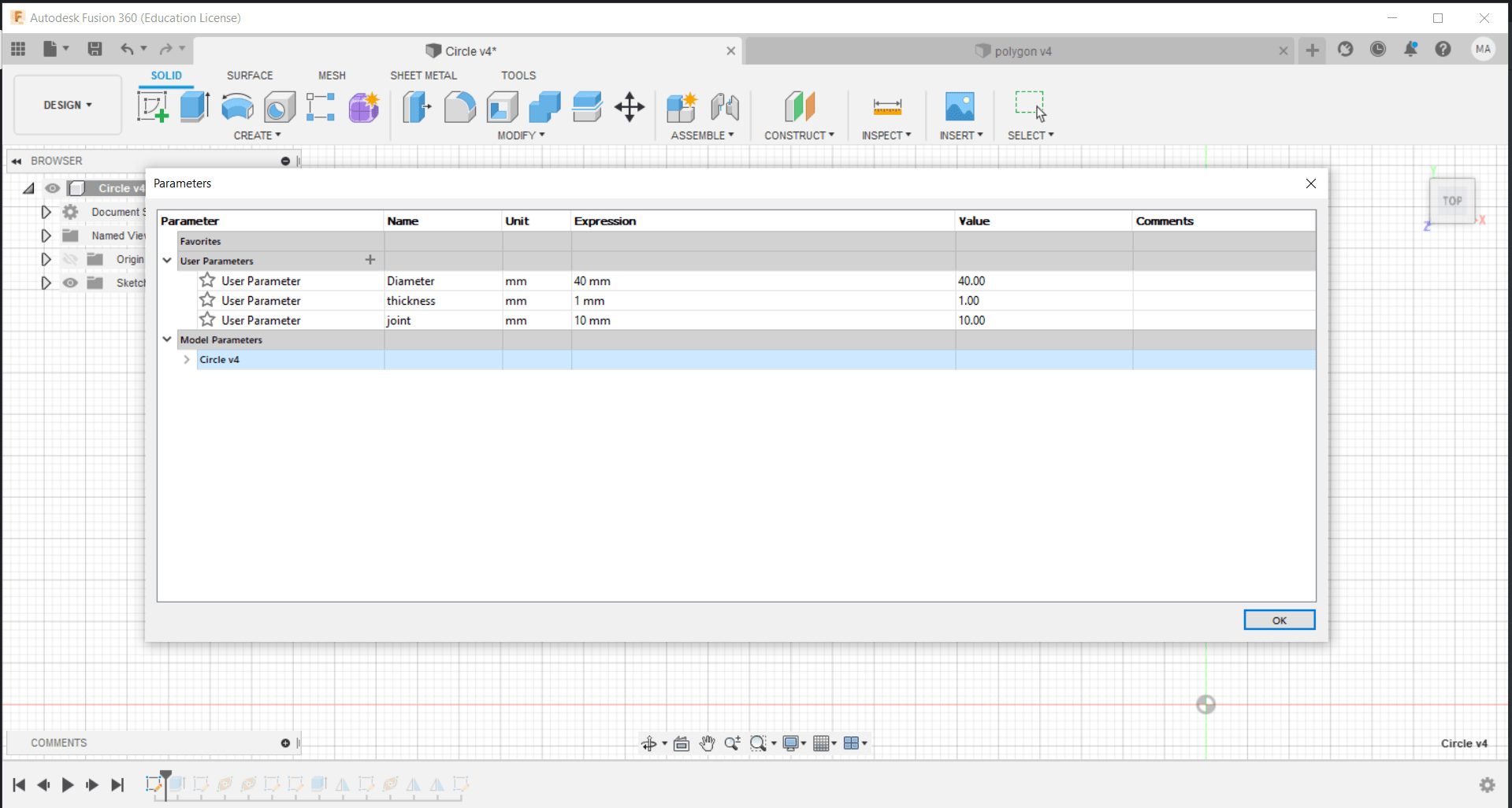
To begin with, a circle with the following parameters was designed, a diameter of 4 cm, a thickness of 1.15 mm same as that of the provided cardboard, and the joint length is specified as 1 cm and its width is same as the thickness of the cardboard to ensure that the pieces get intact. These were put as parameters so that after the joint thickness test is done, we can adjust the width of the joint hole to the obtained value easily. They are set as follows:
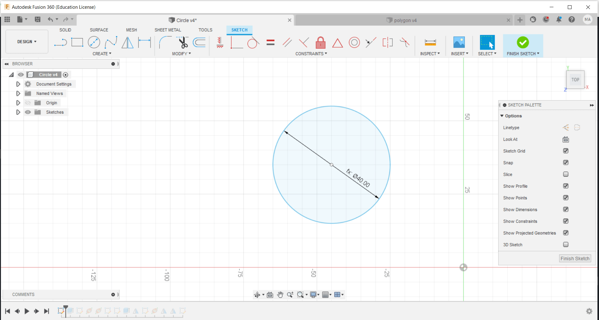
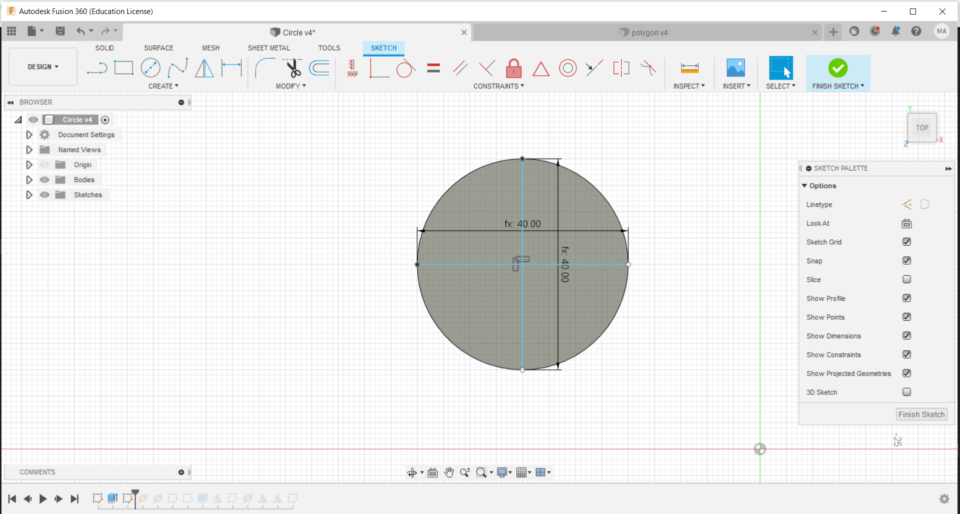
The circle is constructed as follows:
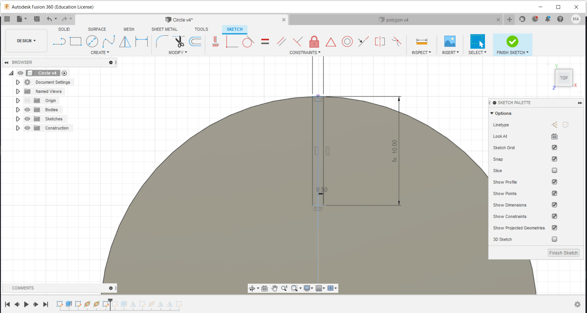
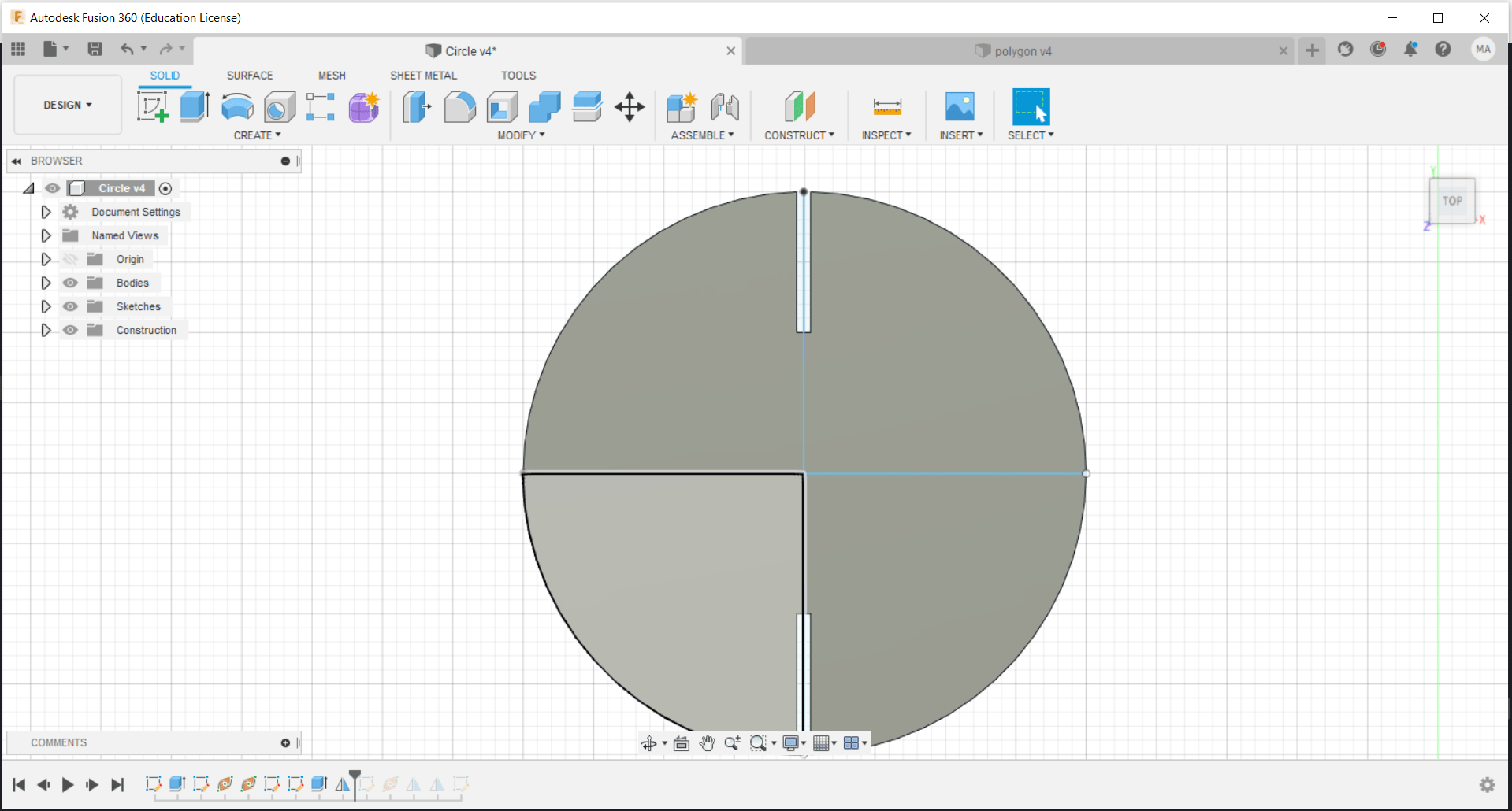
Later on, the design is extruded as to the specified thickness of the cardboard and center lines were made using the sketch for the implementation of mirror planes for further use:
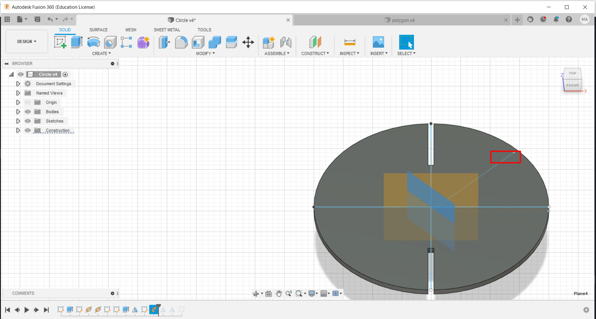
The middle plane was constructed using the mirror along the path command in order to mirror the joints across the circle:
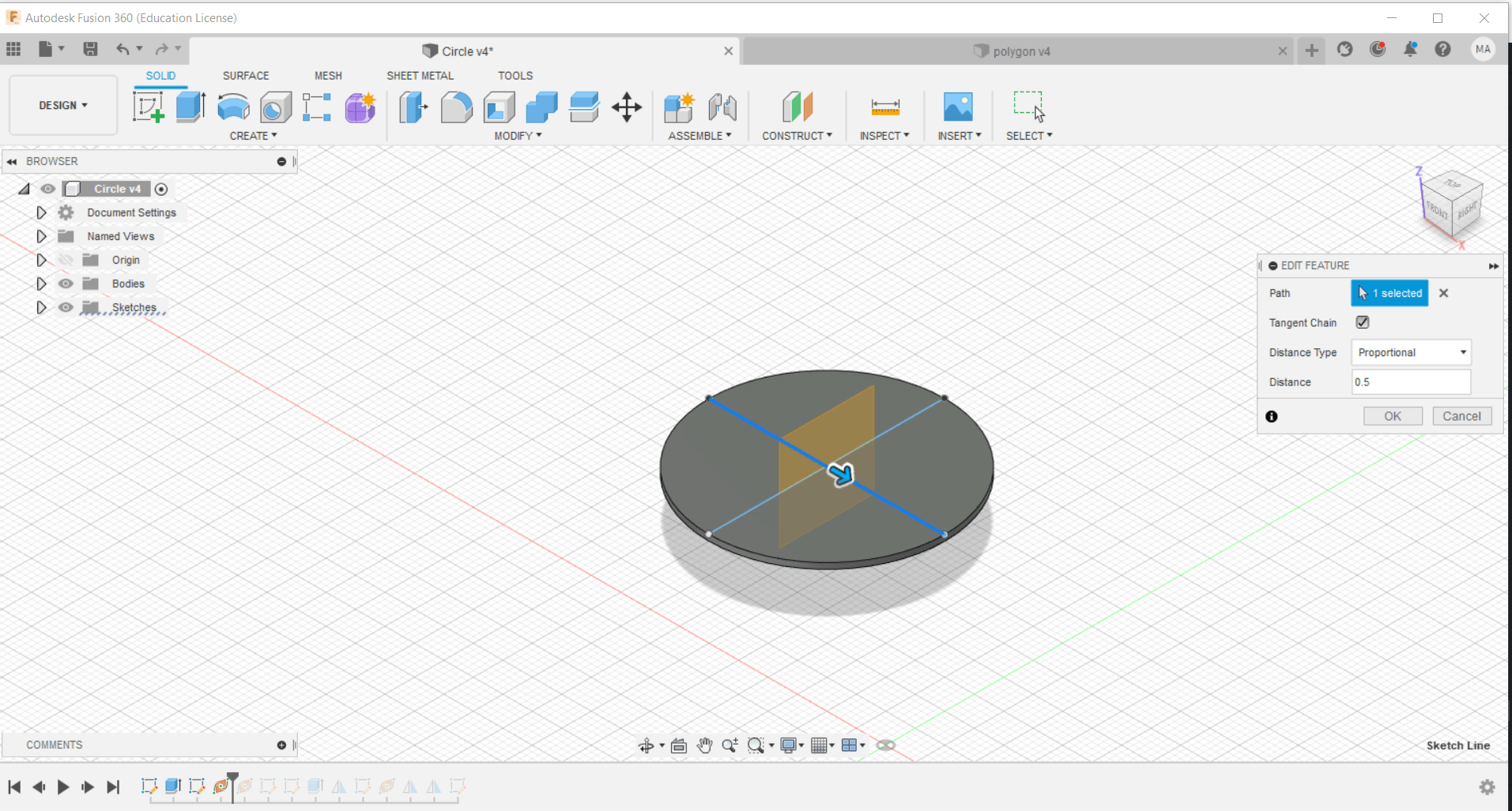
Similarly, the second mirror plane is constructed:
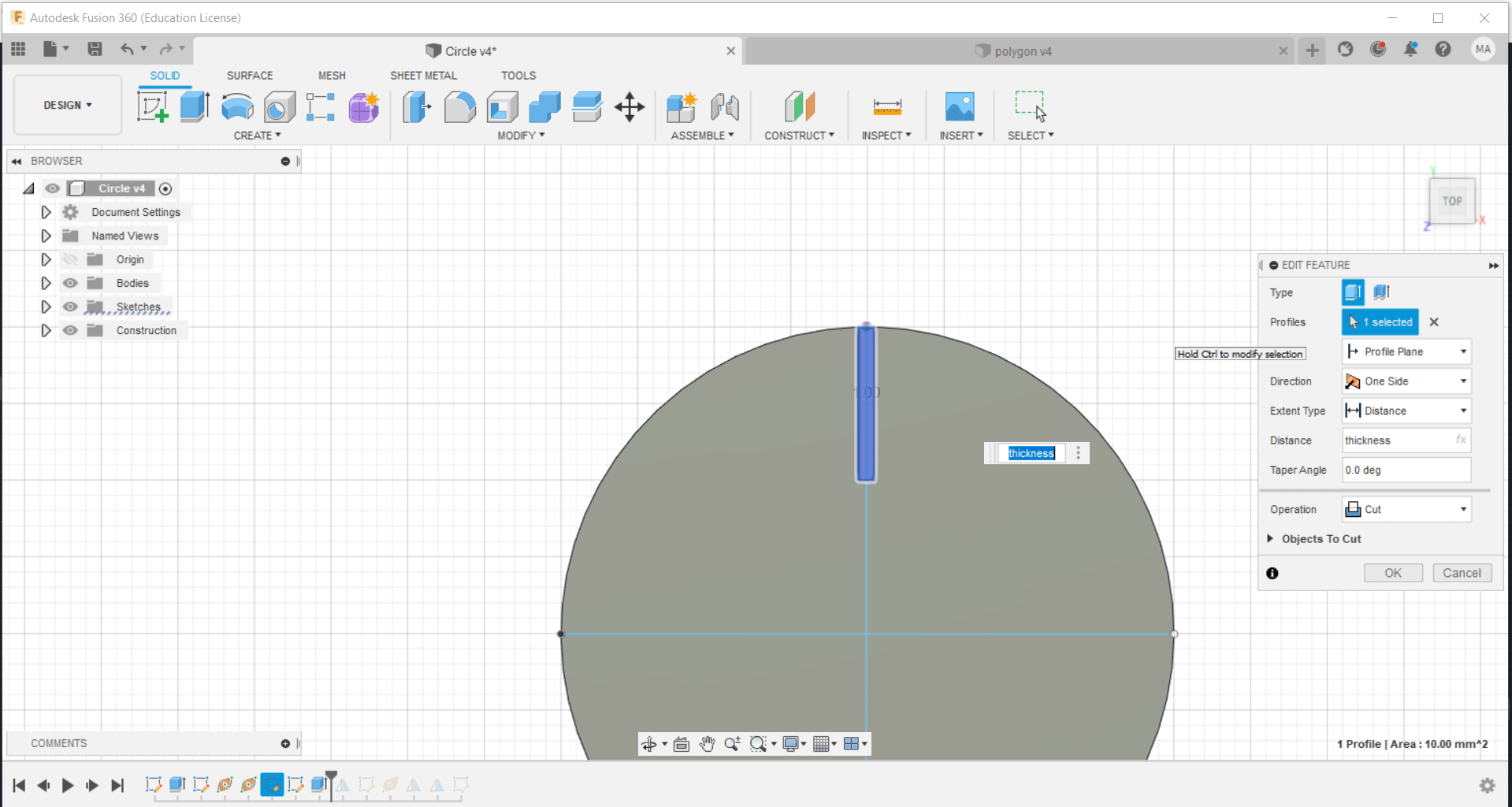
The joint hole was constructed by the following dimensions, note that the joint width is adjusted to 1mm instead of 1.15mm due to the joint test conducted:
The joint hole was extruded with the cut option to make the hole:
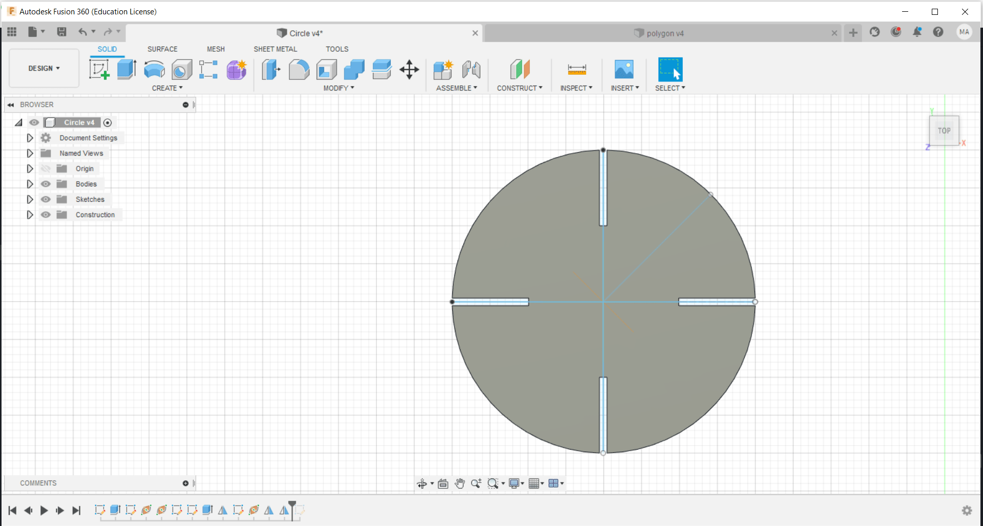
Then, the joint was mirrored across the mirror plane constructed previously:
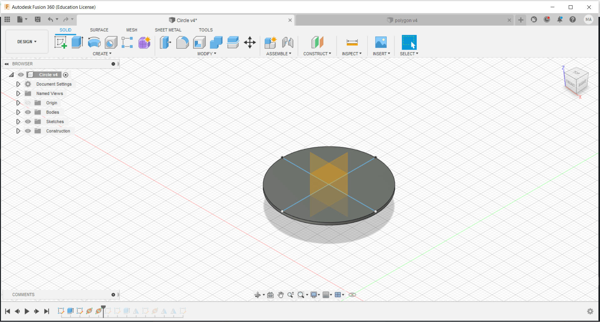
 Then, a line was constructed with a 45 degree with the other two lines to make the last mirror plane used to mirror the joints to the right and left of the circle:
Finally, the last design will look as follows:
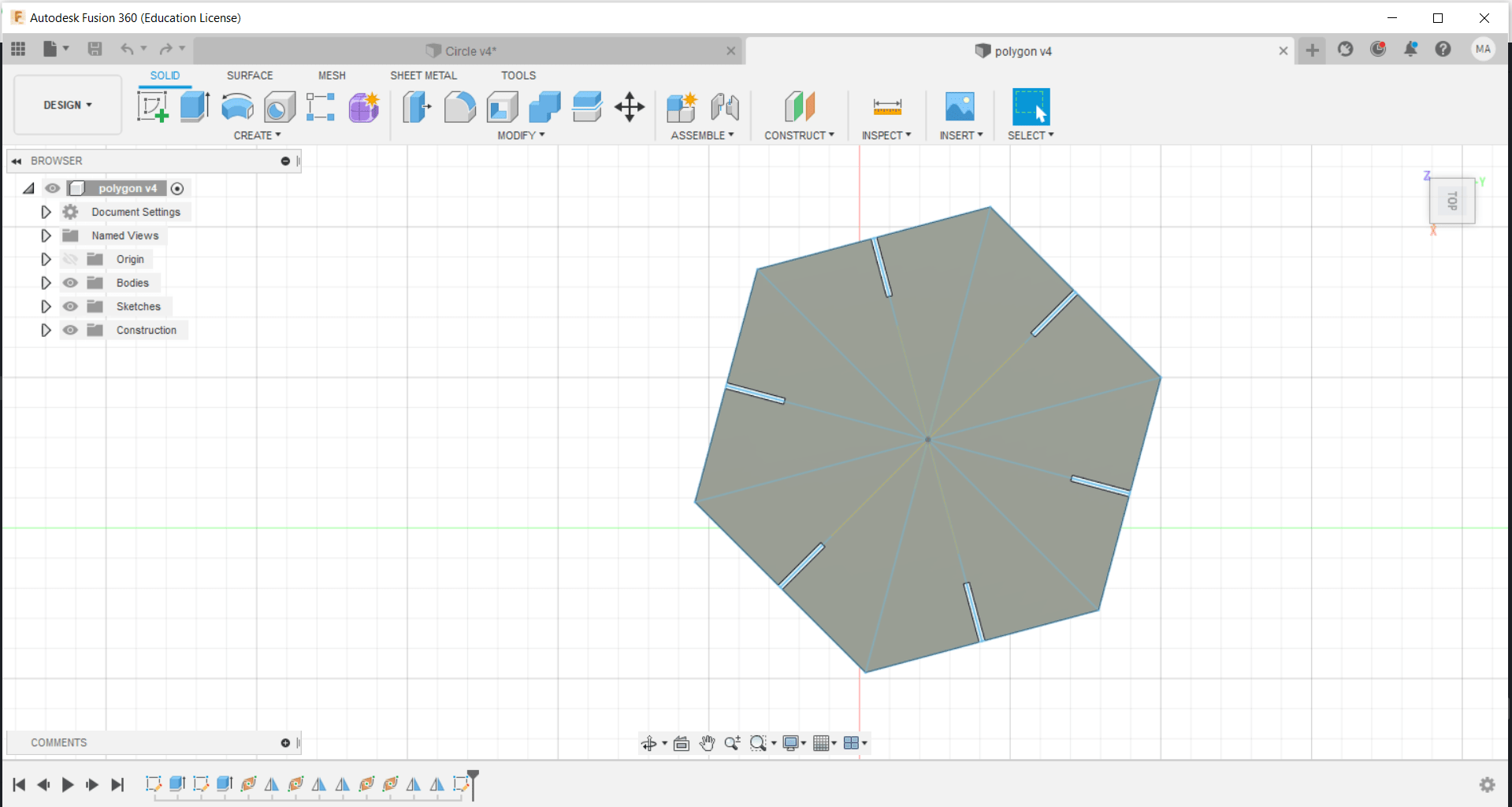
Similarly for the polygon, similar dimensions and steps were followed to design a six edges polygon which yielded the following design:
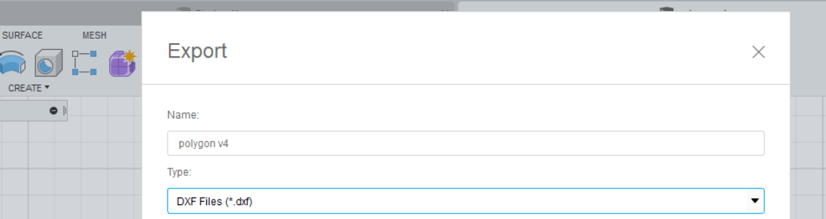
After the complete design of both components, both were exported as dxf files to be used in the CO2 laser machine:
CO2 laser cutter set up:
To begin with, all safety precautions should be obeyed while using the CO2 laser cutter. For example, the blanket used to cover the machine if any fire occurs within the cutting procedure should be present and the user should know how to deal with such relevant situations. The user also should know not to raise the top of the machine without waiting for sufficient time after every cutting procedure, to ensure that the vents do their job of clearing the machine from the residuals of cutting.
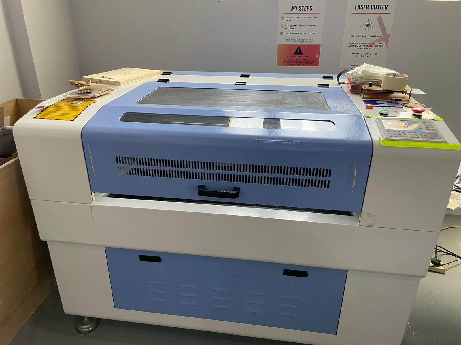
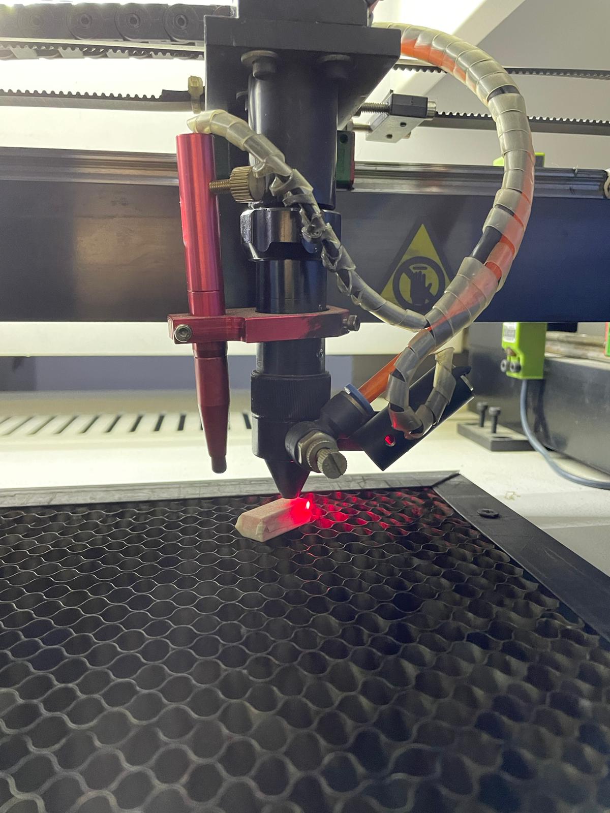
The following pictures show the CO2 laser cutter machine and its respective control panel:
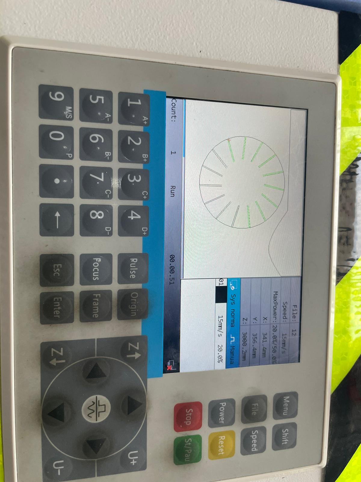
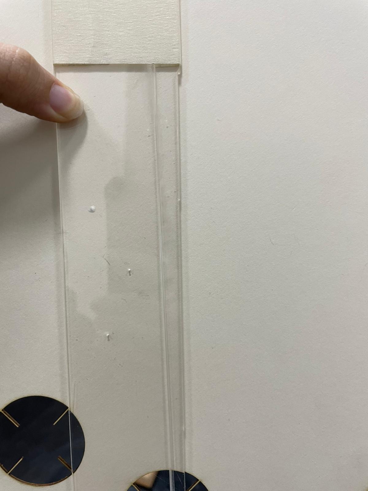
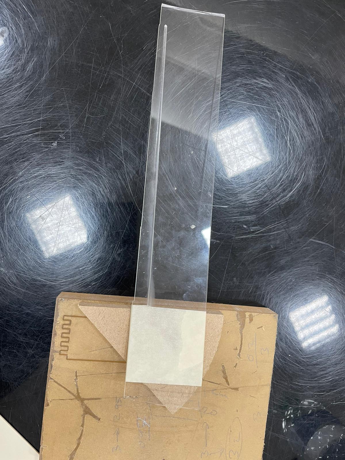
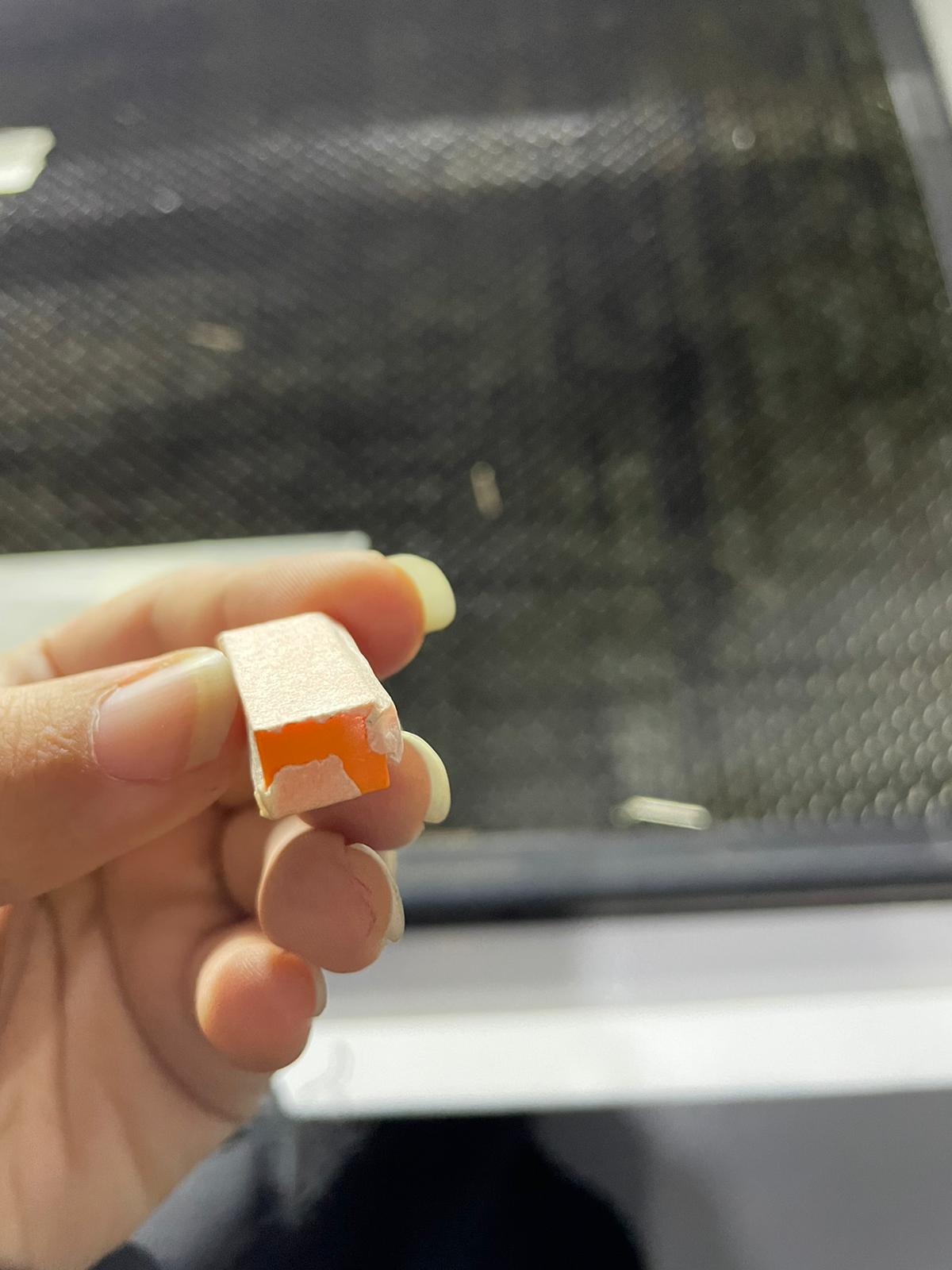
This machine is connected to a computer where the dxf files are imported and used there. After importing the dxf files to the computer, there are used and arranged depending on the what is needed and in the most optimum way to use the least cardboard possible. Then the files are downloaded and the cutting procedure is ready to go, but before that, a focal length test is conducted, where an inclined surface is utilized to get the focal length between the lens and the inclined surface by the utilization of mathematical relations on the least narrow point on the cutting path along the inclined object. It was found that the focal length is approximately 8 mm (i.e. 0.8 cm) which is then set up by the utilization of a lego block that was covered with tape to get 8 mm height.
jpeg
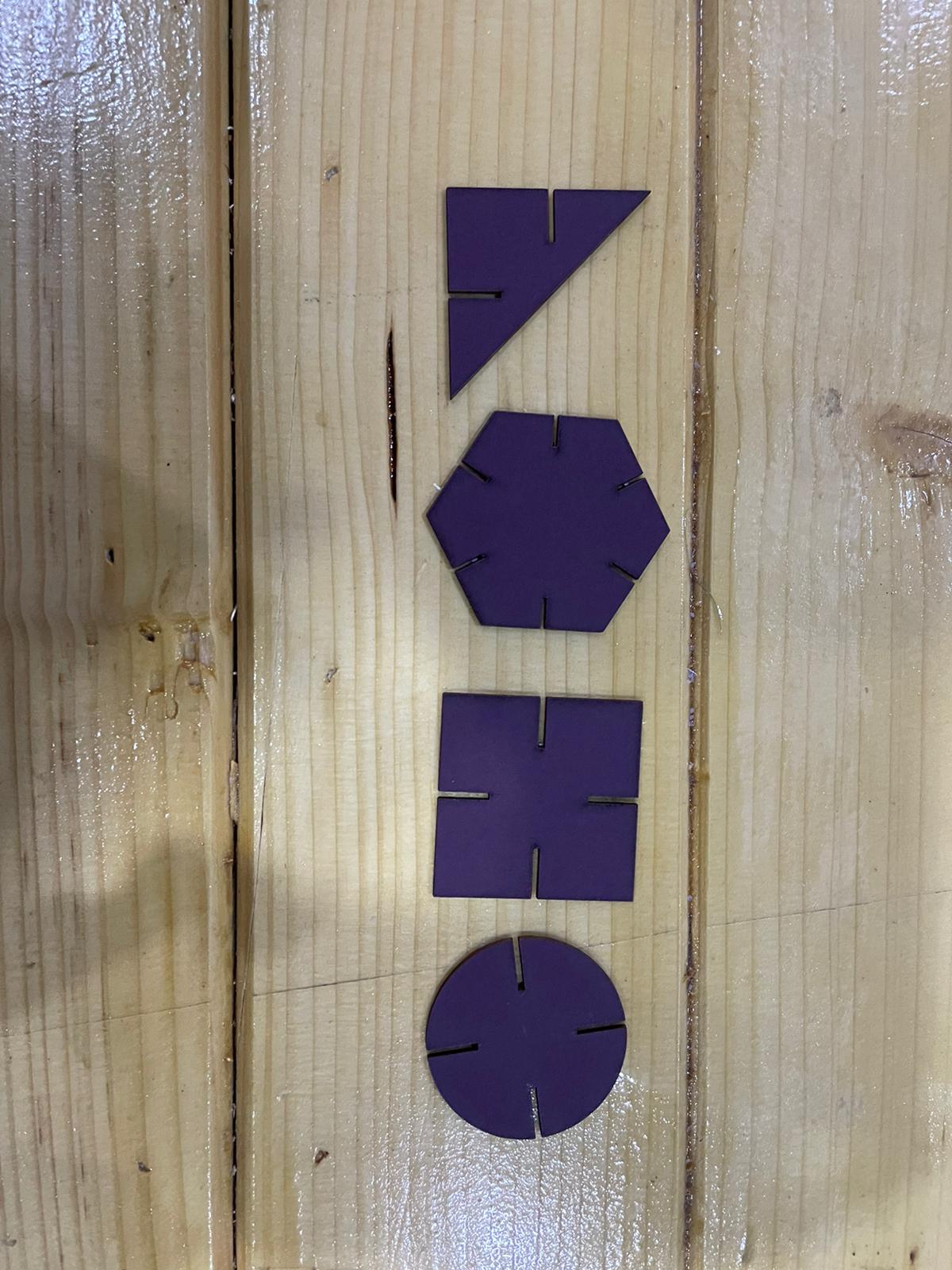
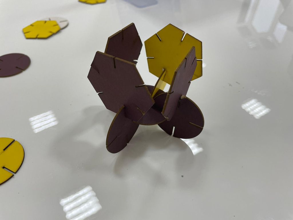
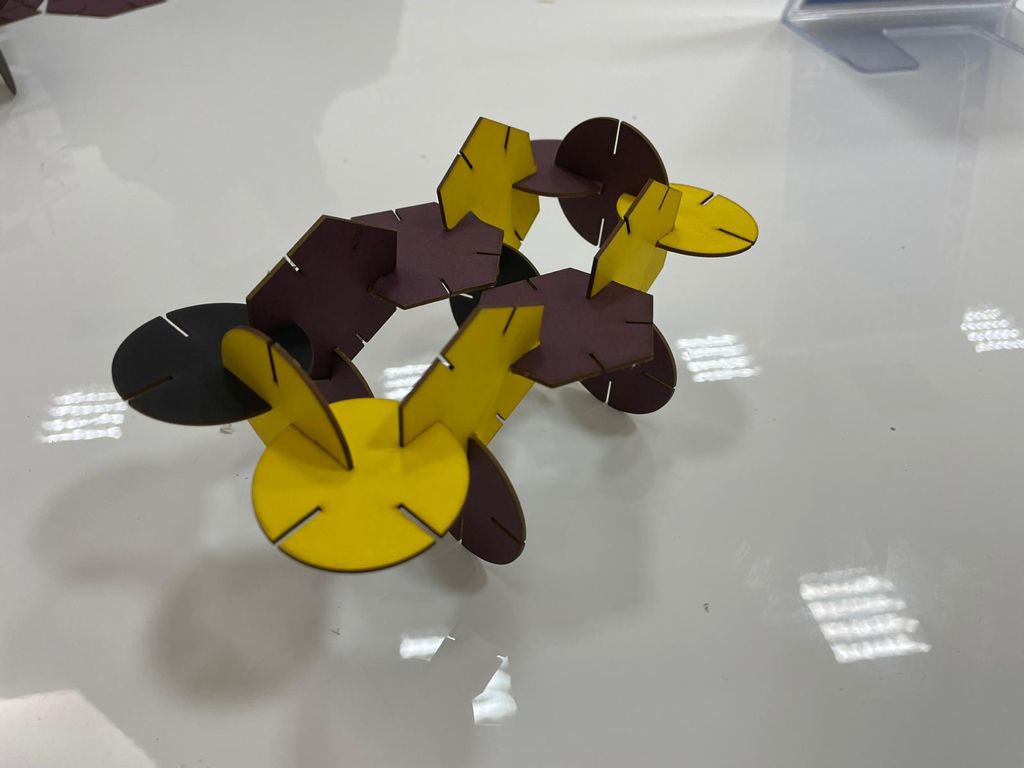
After that, the cutting procedure was conducted yielding the following 4 shapes, of which, the circle and the hexagon were made by me, and the square and triangle were made by my colleague Batool:
With the addition of all these shapes, the following design of a car was obtained, utilizing the triangular shapes as joints and direction changers, the squares as the body of the car, the hexagon as wings for the car and the circle as both stabilizers at the middle between the body parts and tires for the car. The final design looks as follows:
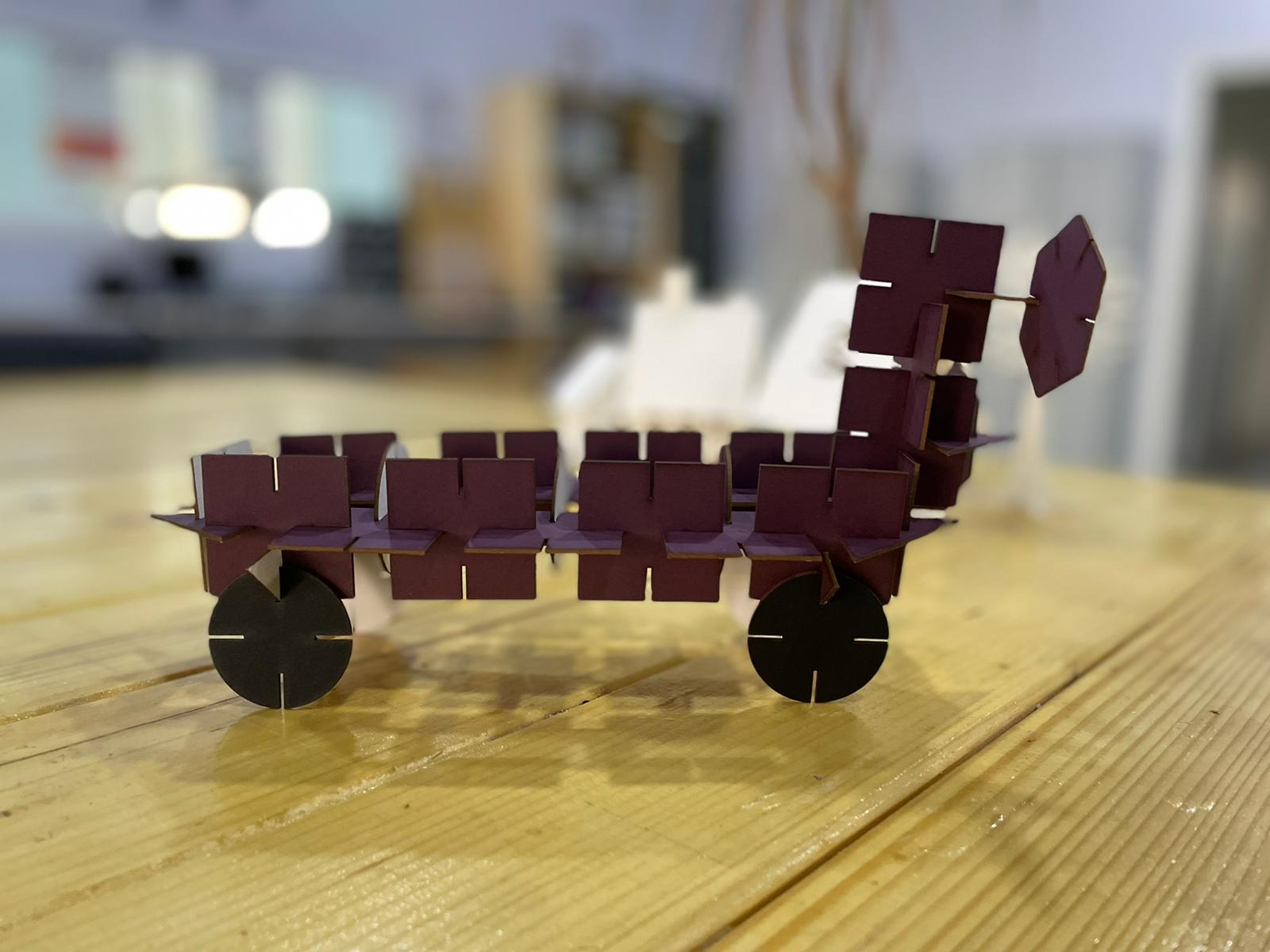
These represents the designs I made with my parts only:
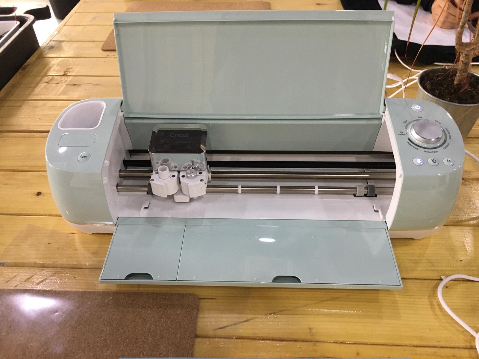
Vinyl Cutter
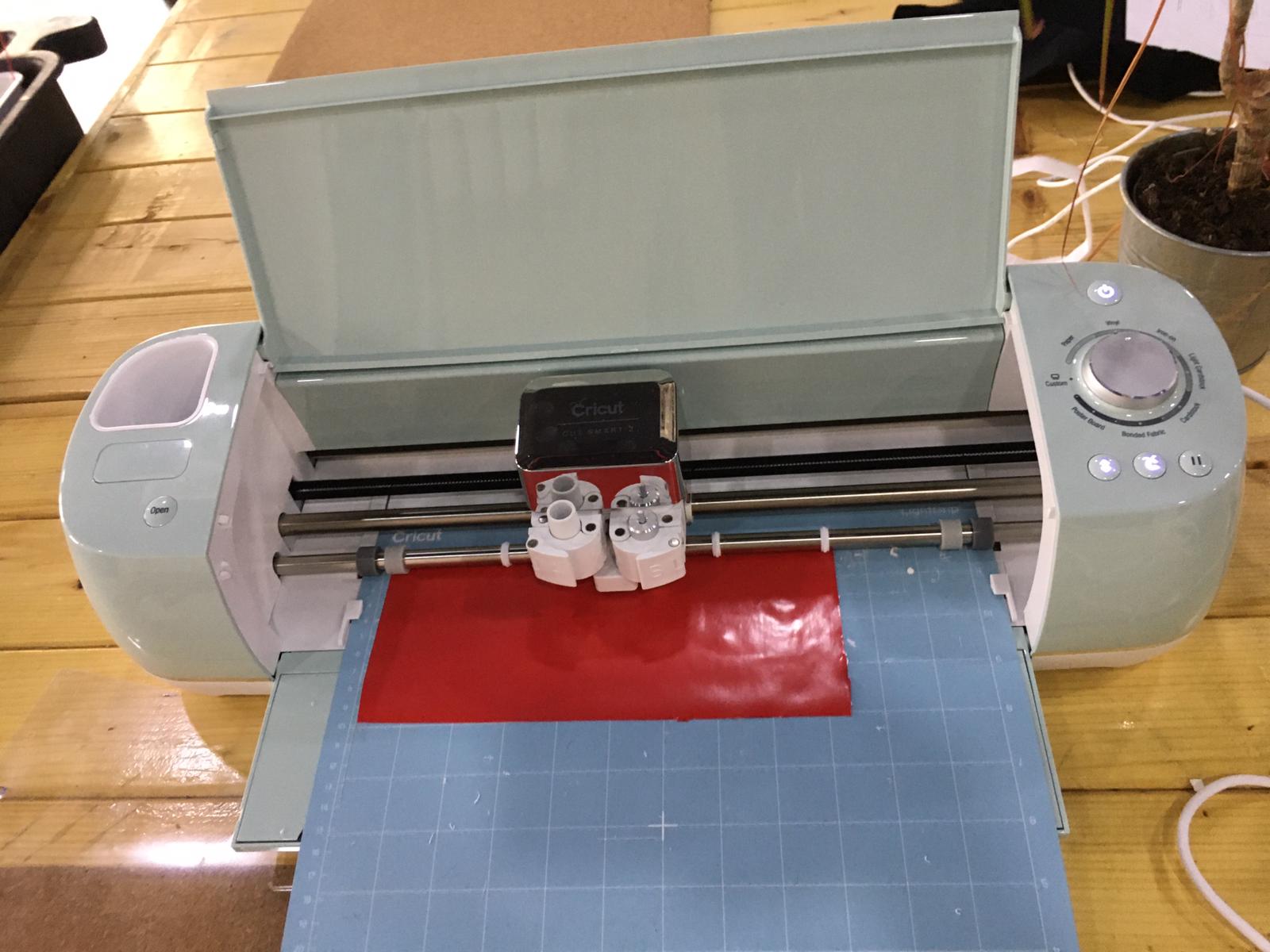
The vinyl cutter was mainly utilized here to make 2D designs into stickers that can be utilized for various purposes. The vinyl cutter uses blades with a command coming from a specific software to cut the imported design on the sticking sheet, in a neat and fashion way. The vinyl cutter looks as shown below:
The Design
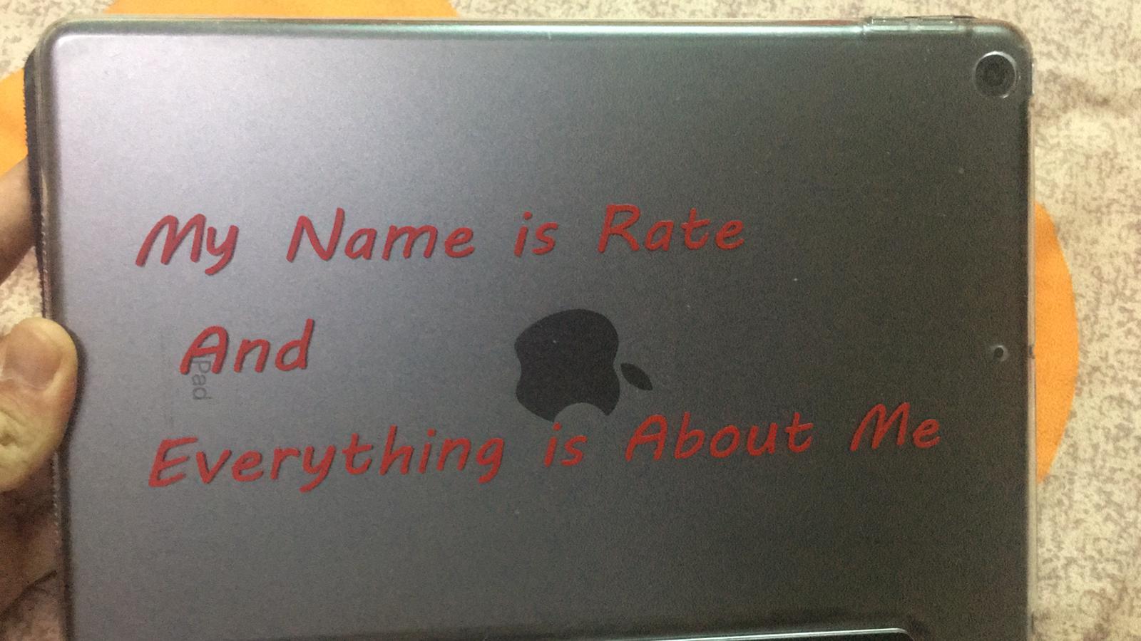
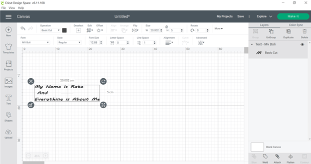
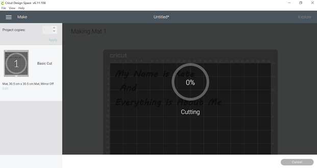
A simple design was constructed adopting another famous quote of Dr Shaker Haji stating ” My name is rate and everything is about me “. It was done through cricut design space where the quote was written accordingly after starting a new design:
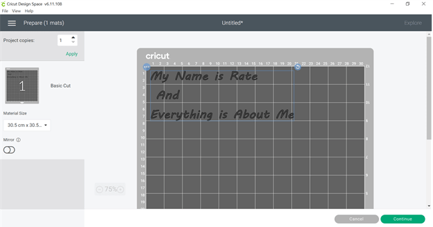
After that, the design would be adjusted based on the location of the sticky sheet used:
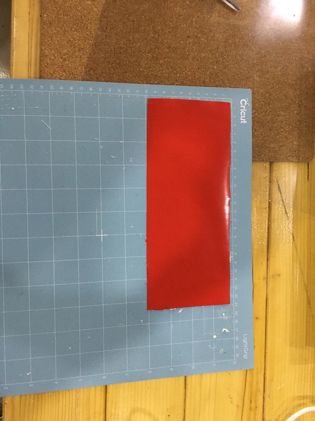
A sticky sheet is adjusted based on the dimensions of the design with an extra offset to ensure the cutting procedure succeeds and it does not go off the edges. Later on this sticker is put into the sheet used in the vinyl cutter:
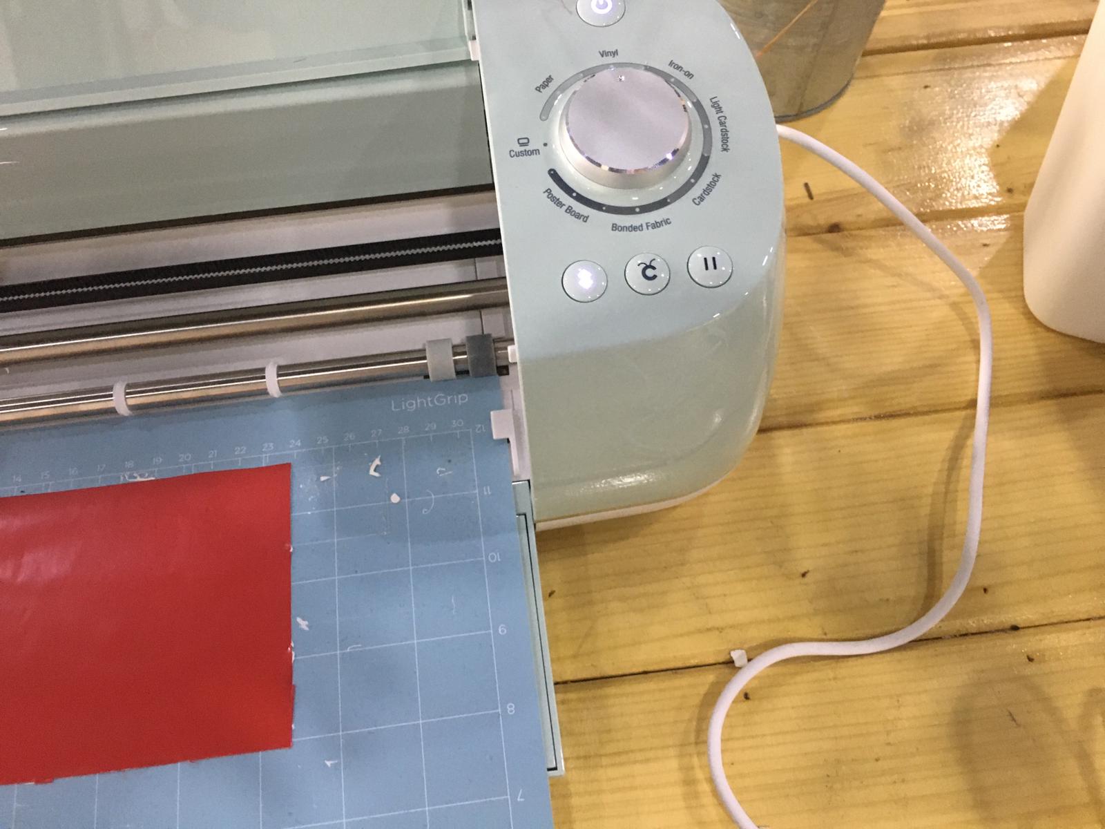
After that, the sheet is put inside the vinyl cutter to fit it inside the machine to prepare it for cutting:

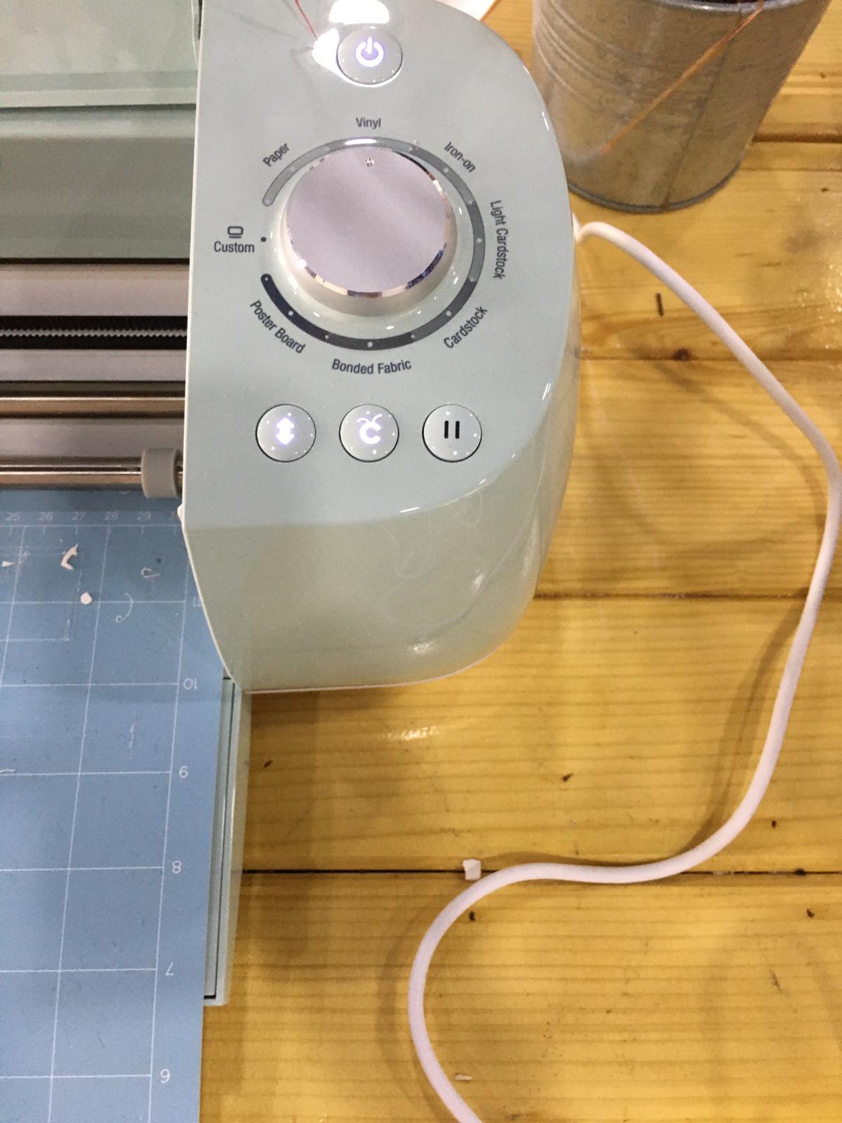
Then, this button will flash which would be later pressed to fit the sheet inside the vinyl cutter
After fitting, the sheet will look like this:
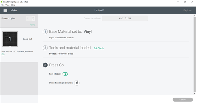
After continuing from setting the design on the sheet, the following page will pop up stating some information with regards to the vinyl cutter and the operation:
If everything ready, press the following button to start the cutting process:
The following page will show indicating that the cutting started:
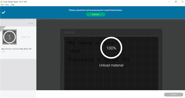
Then after the cutting is done, this will show up informing you to unload the sheet, same button used to fit the sheet will remove it:
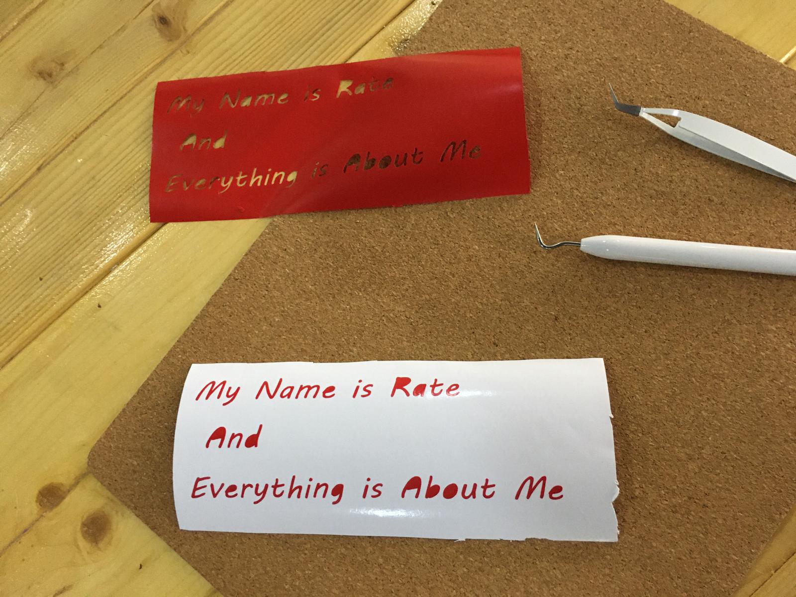
This is how the sticker will look after removing the sticky material surrounding the words, note that the tools in the picture are used to remove any excess material between words and letters or even inside the letters, to ensure the best possible view:
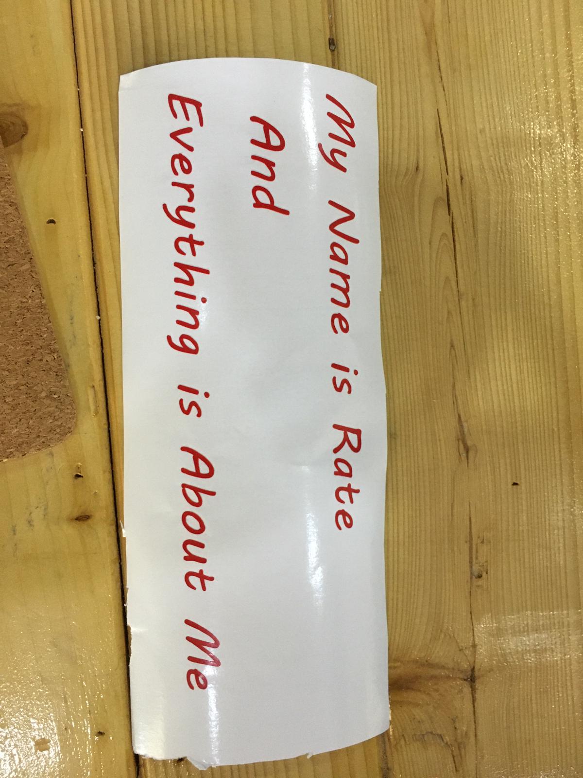
After removing the excess material, the design will look like this:
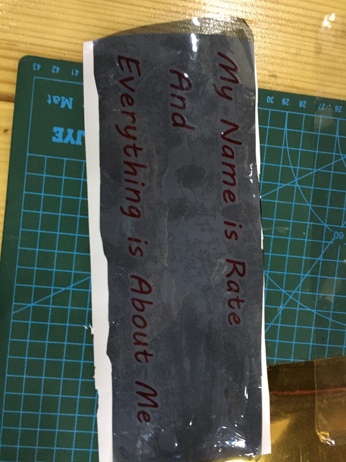
The black sheet here, is used to stick on the sticker and removing it from the blank sheet as a whole, and then is applied to the place where you want to stick your design, this allows for easier transferring of the whole quote in one time as a whole, rather than taking each letter separately:
The final design will look as follows: