Fab Academy Project: Microsyringe Pump
The ninth week’s task was to develop a project relevant to our engineering field that comprehends all the learnt knowledge and skills from the previous weeks. The project me and my colleagues decided to execute is the microsyringe pump. Microsyringe pumps are small pumps that gradually discharge fluids at minute amounts due to an applied pression force. The instrument complies with the Archimedes’ screw principle which allows the fluid to be pushed to the discharge of the syringe due to an applied force that permits the syringe displacement based on the conducted pression force. Consequently, the flowrate discharged from the syringe pump depends on the force applied. Microsyringe pumps are widely known for being used in the medical sector and microfluidics. The project can be separated into three parts. Firstly, the design of the microsyringe pump structure and supports. Secondly, the electronics including the programing and connections. Finally, assembling the parts and electronics to yield the finalized microsyringe pump. I mainly worked on assembling the parts and electronics, the electronics connections and some brief coding and programing of the instrument.
Design
The design used for this project was adopted from a pre-established project which is considered as the most common design for microsyringe pumps. Tinker CAD files were exported and scaled to meet the specified criteria which were later printed in the 3D printer.
More details about CNC milling machine fabrication can be found in Zahra’s page here.
Electronics
The electronics used in the microsyringe pump are the power supply, the Arduino nano microcontroller, the driver, the stepper motor, the on/off switch and the direction switch.
Stepper Motor and Driver
The stepper motor is an electrical motor that utilizes the electrical energy to rotate the attached shaft. The shaft (i.e. the threaded rod) rotates on a stepping manner based on the specified speed for the motor and the received pulsive signal. The driver utilized for the microssyringe pump is a microstep driver which further divides the steps of the stepper motor. With the presence of the microstep driver, the shaft rotates less than a full step with each received pulse.
Power Supply and Arduino Nano
The power supply converts the electrical power attained from the source into the specified voltage for the application. It is the main source of power for the electronic parts. The connections of the wires were done based on the given pinout datasheet to get the best results out from the power supply. The Arduino nano microcontroller was utilized as the heart of the electronics of the microsyringe pump by controlling the instrument, as it connects all the parts on a single part and gives commands to them accordingly based on a constructed code. The Arduino nano was placed on a breadboard and connected to a laptop.
Direction and On/Off Switch
The on/off switch was added to be able to start or shutdown the instrument directly without the need to stop the microcontroller. It is very important to prevent accidents as whenever it is expected that the syringe reached the end, the button is directly pressed. The direction switch was added to alter the direction of the motor rotation which yields in moving the piston forward or backward based on the position of the direction switch.
More details about electronics can be found in Batool’s page here.
Assembly
There were two major things to be assembled which are: the microsyringe pump which consisted of 3D printed parts, and the compartment to stabilize the microsyringe more and to house the electronic devices.
Microsyringe Pump Assembly:
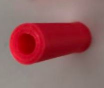
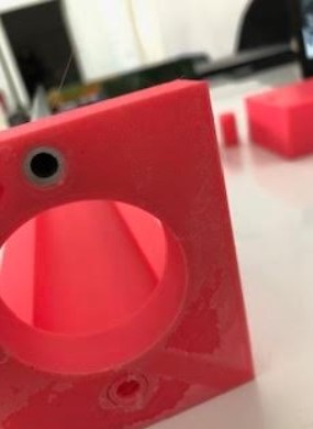
After the completion of the printing process, the syringe holder was fitted to the base hole. It was found that the hole was quite wider than the syringe tip. Therefore, a compatible part was made to be put inside the syringe holder to accommodate for the size difference between the syringe holder and the syringe tip.
The piece looks as follows:
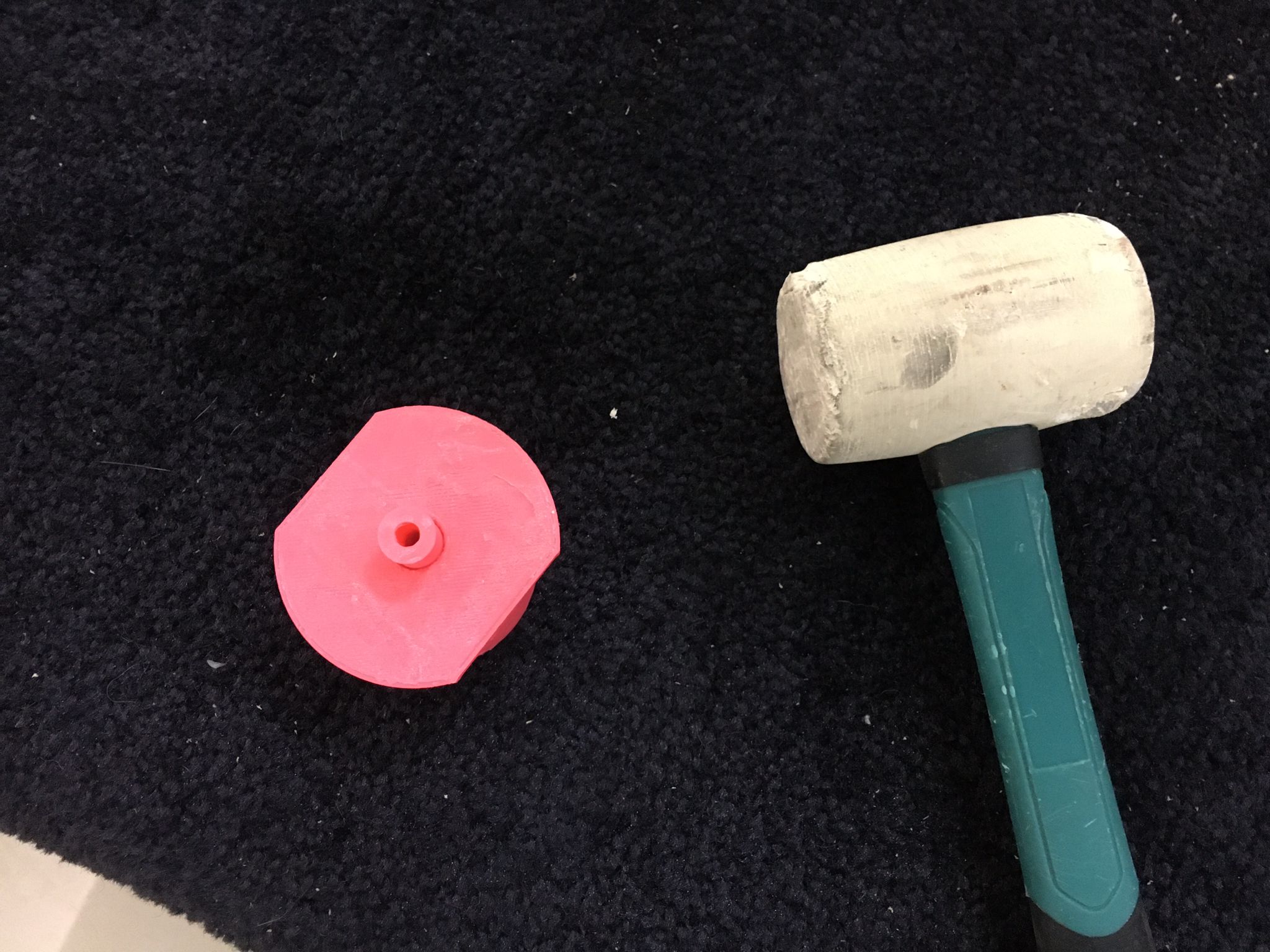
This piece was assembled by using a hammer to fit the piece in the syringe holder as follows:
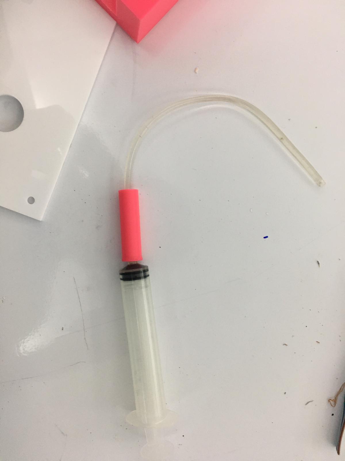
This yielded in the syringe fitting perfectly:
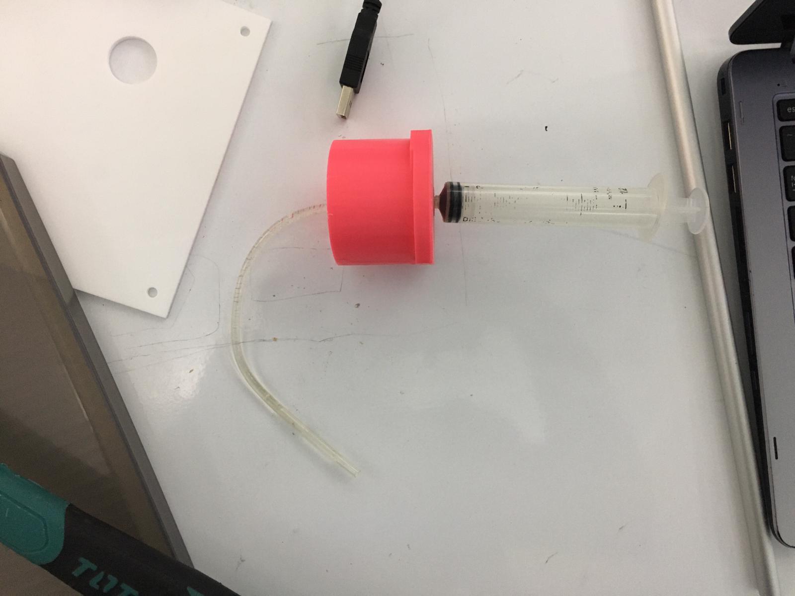
The tube was fitted to the syringe through the piece which is previously fitted to the syringe holder:
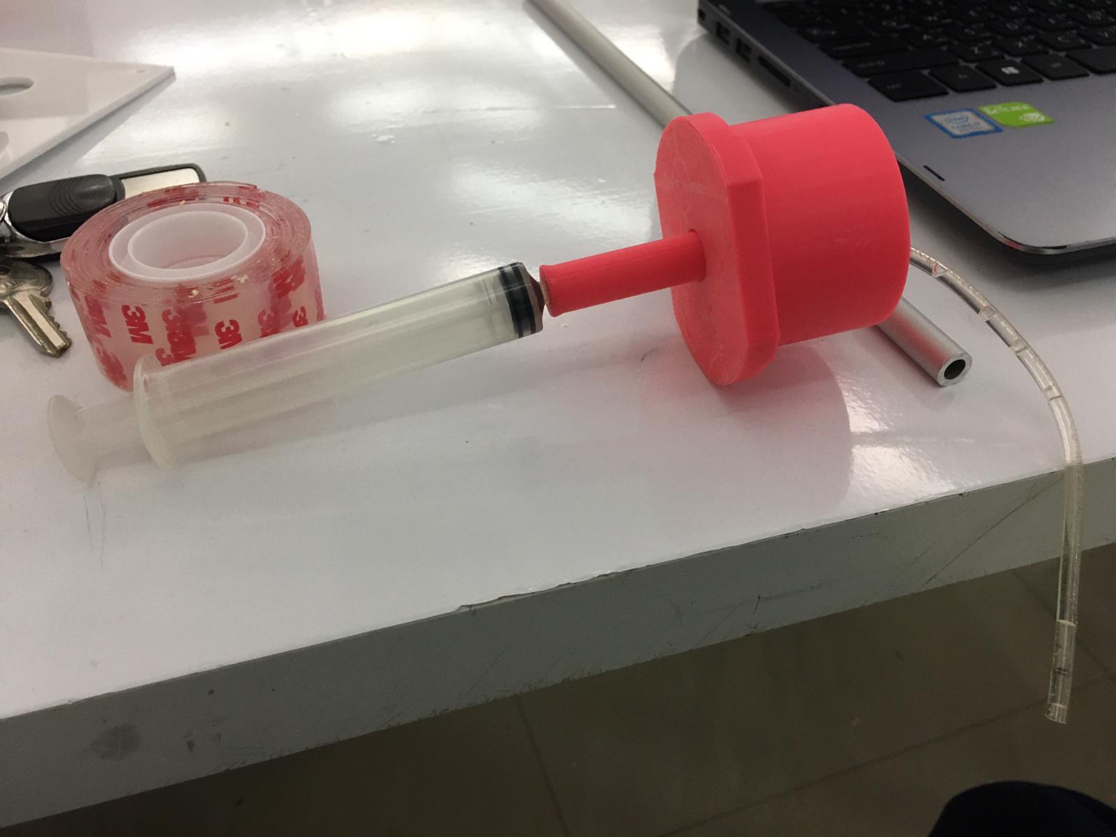
The syringe holder was connected to the base.
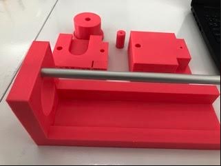
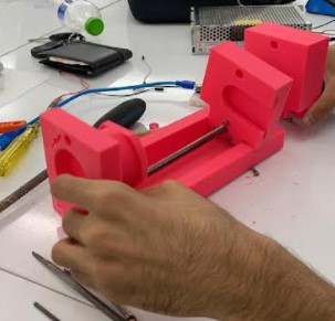
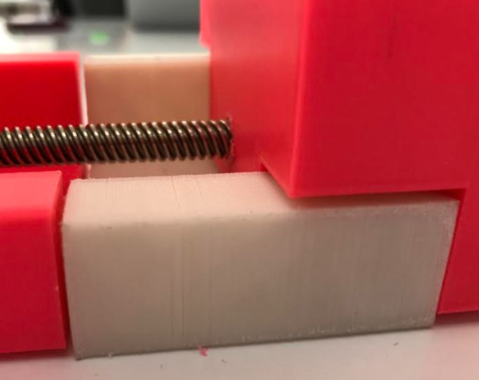
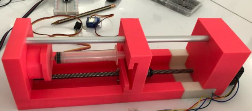
The motor support, piston and the base were all put together as per the design specifications. The respective parts (i.e. motor support, piston and base) all had holes at the top and the bottom of the structure which were used to fit the non-threaded and threaded rods respectively. In addition, those parts were connected by a non-threaded rod to ensure the stability of the microsyringe pump while operating. The non-threaded rod is connected as follows:
The stepper motor was connected to these parts through a threaded rod which was mounted to the stepper motor end. The following picture shows me fitting the threaded rod to the associated parts:
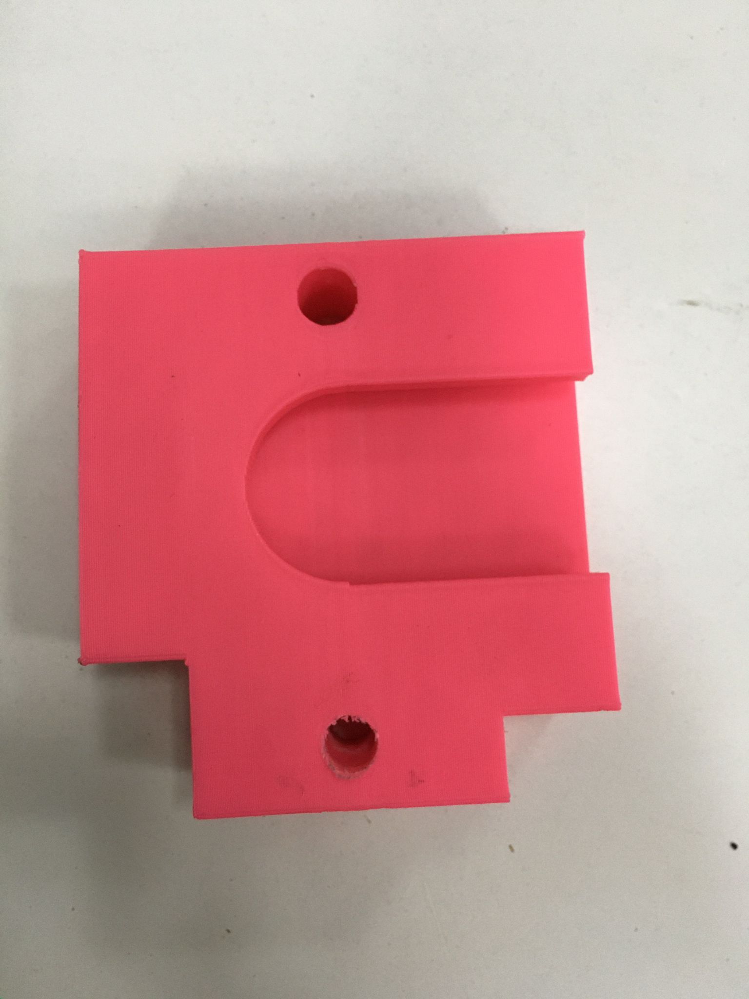
It was noticed that the threaded rod is larger than the executed design and therefore an extra part was made to account for the extra length. The extension looks as follows:
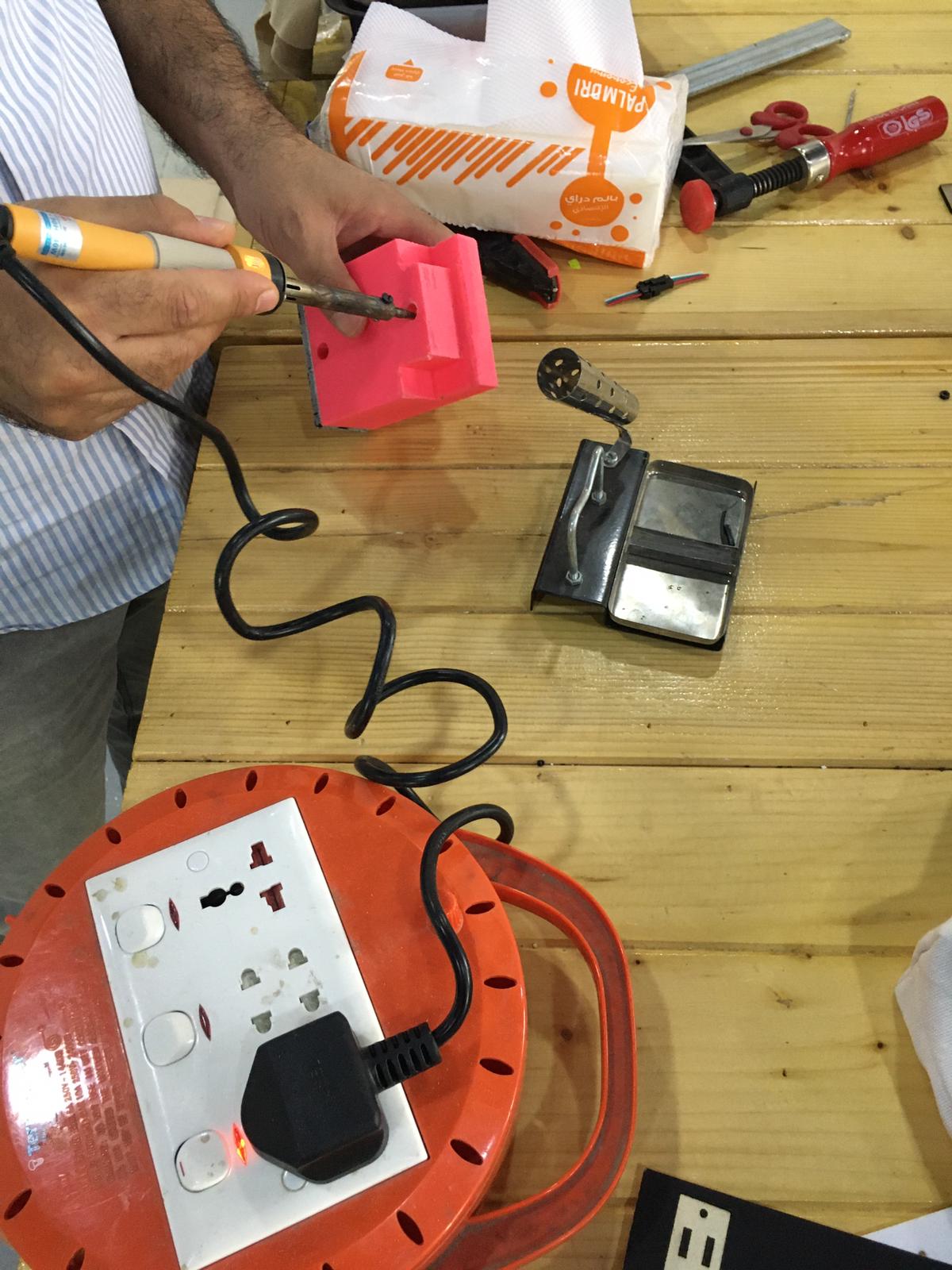
The threaded rod was not fitting in a straight line due to the holes in the motor support and the base are not on the same line, as a result, the motor support hole was expanded by melting some of the material inside the hole, this was done as follows:
Also, the coupling was mounted to the piston so that the movement as a result of the force conducted by the motor can be directly affecting the piston. a pencil is used to mark the place to be drilled so that screws are fitted there to fit the coupling with the piston:
Finally, all the parts were adjusted and fitted together again, yielding the final microsyring pump structure, which also demonstrated the coupling and the piston which are fit together:
Compartment Assembly:
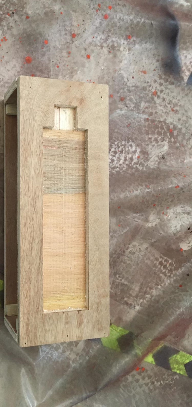
The compartment is made from 4 wooden faces fabricated by the CNC machine and two acrylic faces fabricated by the CO2 laser cutter. After the pieces were fabricated, they were taken to be assembled. The top piece had an engravement for the stepper motor and the microsyringe structure for fitting purposes. This engravement looks like this:

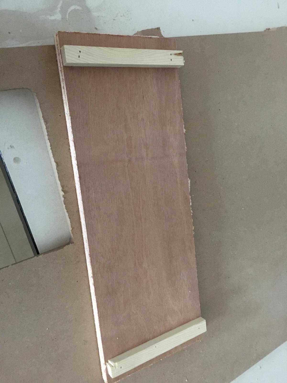
In addition, the bottom of this part was adjusted with supports for easier assembling of the parts:
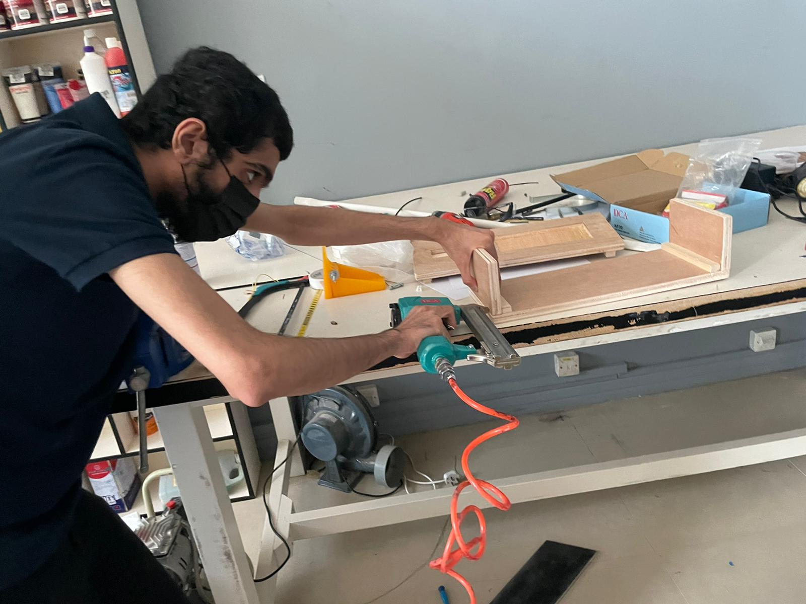
The supports, and the wooden parts were assembled by the utilization of the nail gun. The following picture shows me using the nail gun to fit the parts together:
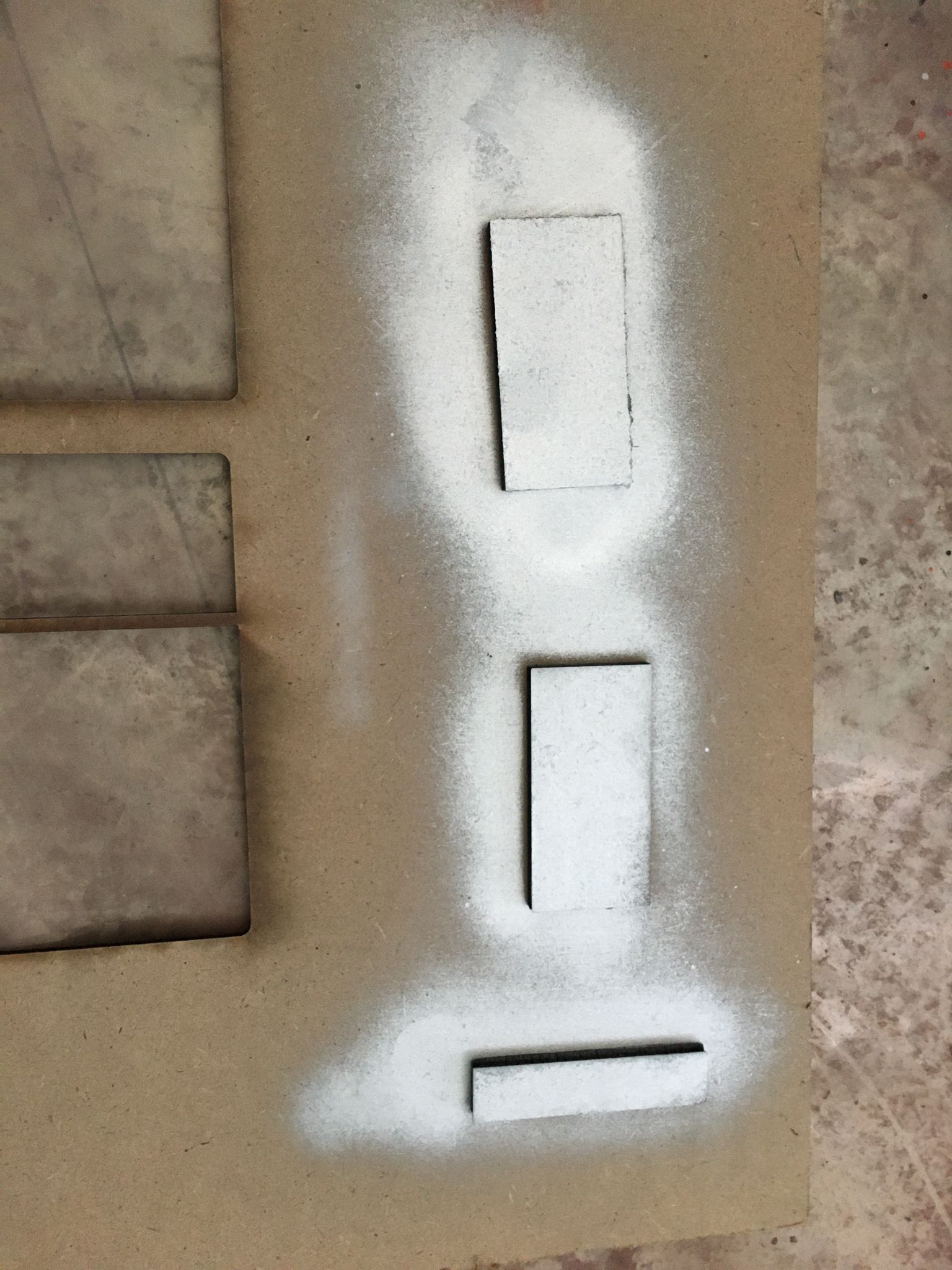
Finally, after assembling the wooden parts, the compartment will look as follows:
The compartment was painted with a silver color which looks as follows:
After fitting the compartment, the microsyringe pump was tested whether it fits or not, it was concluded that the structure fits and achieves the required purpose.
The pre-established acrylic faces were fitted by pins which is illustared down below:
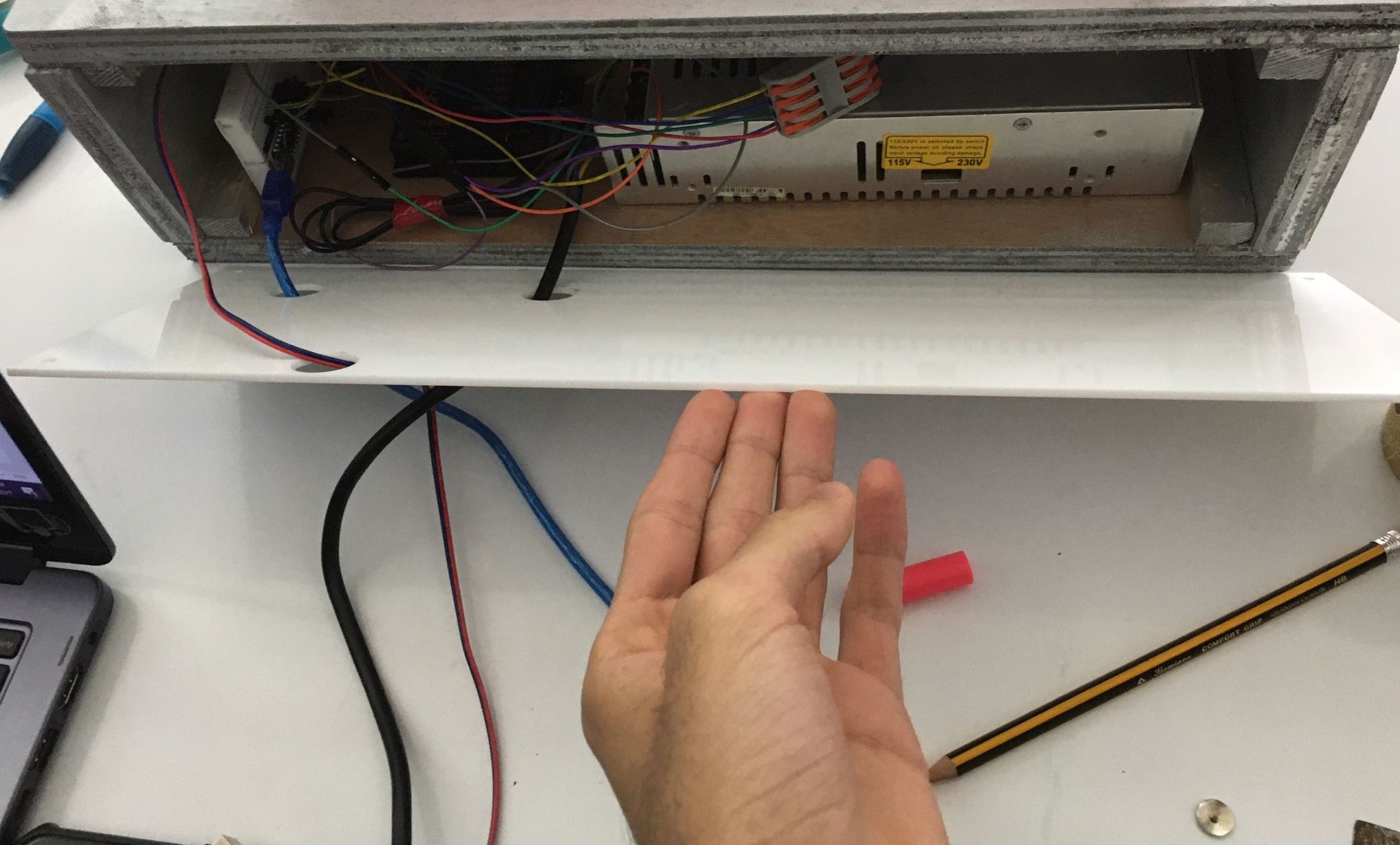
The electronics fits quite good inside the compartment which is demonstrated below:
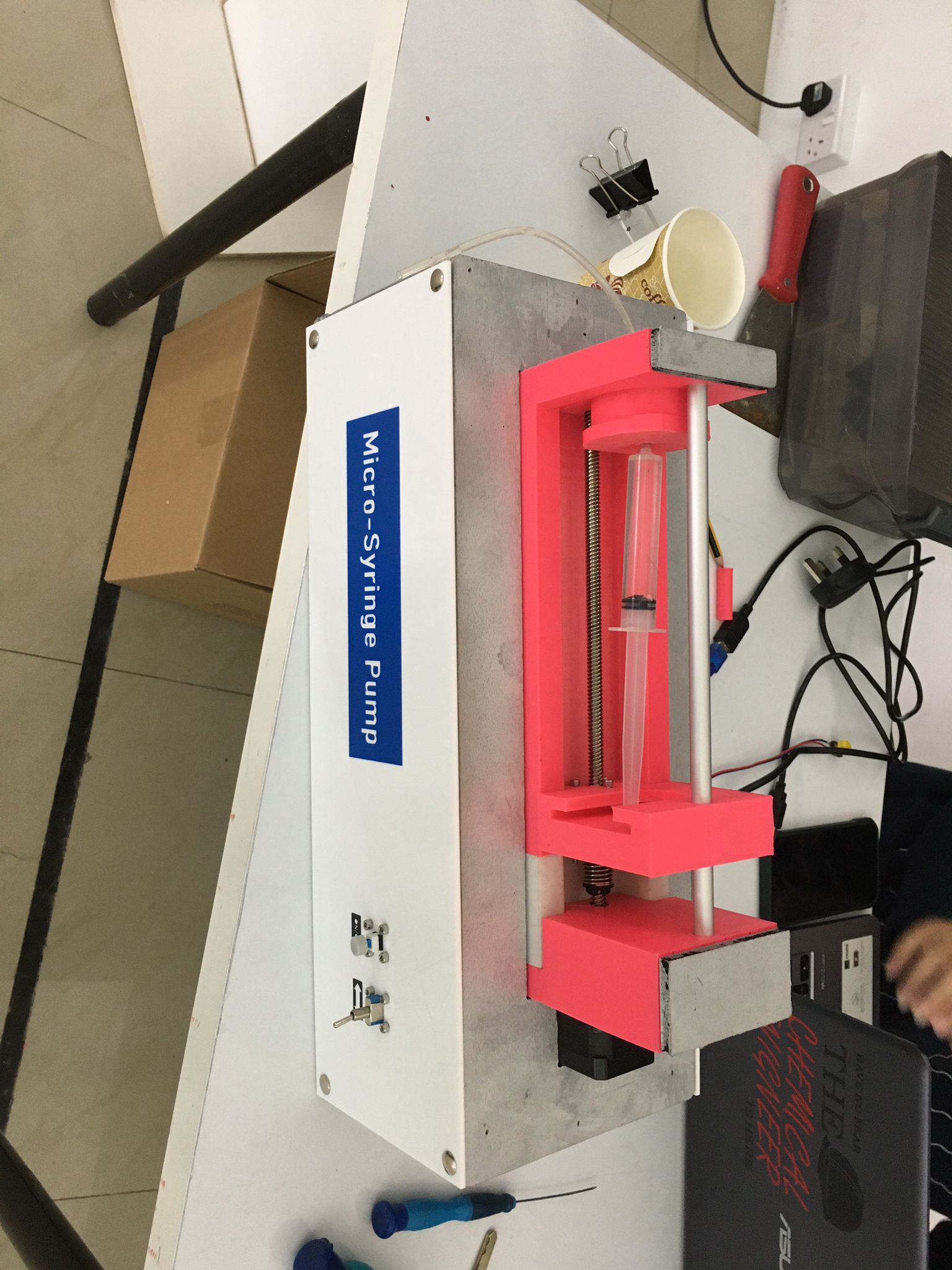
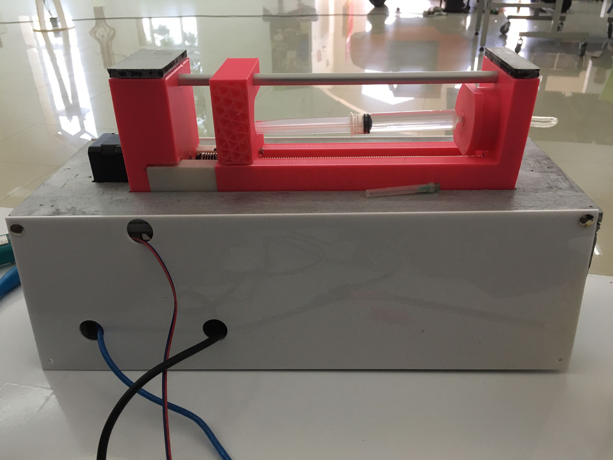
The final outcome of the whole assembly looks as follows:
Front view:
Top view:
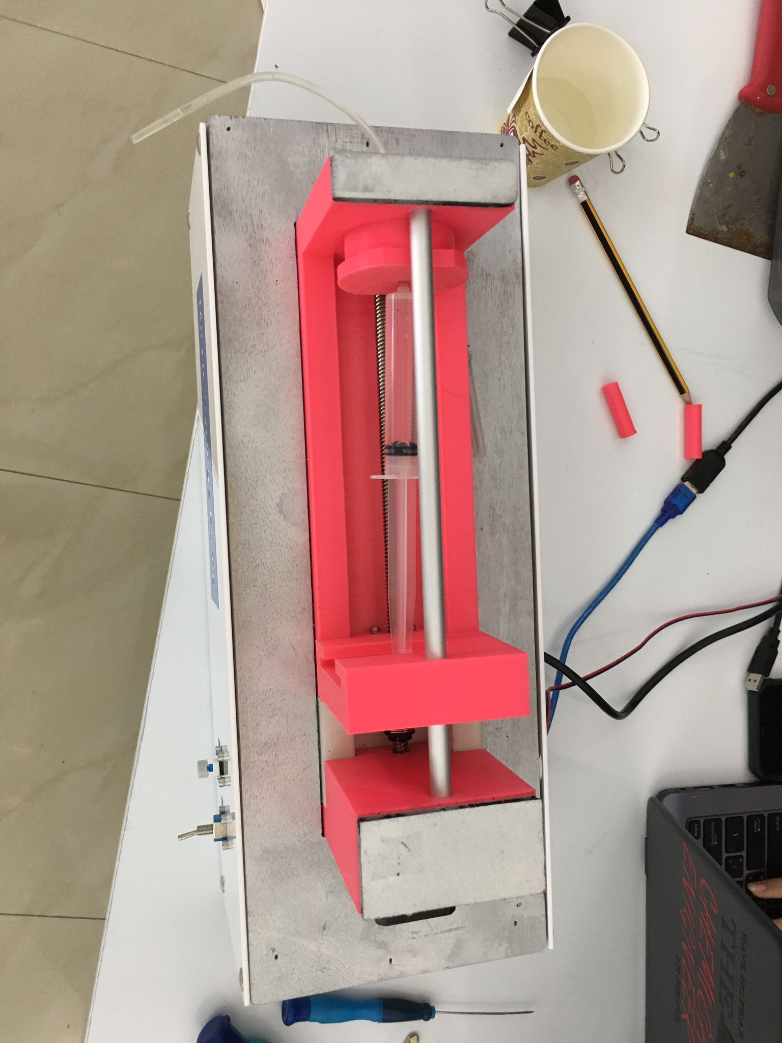
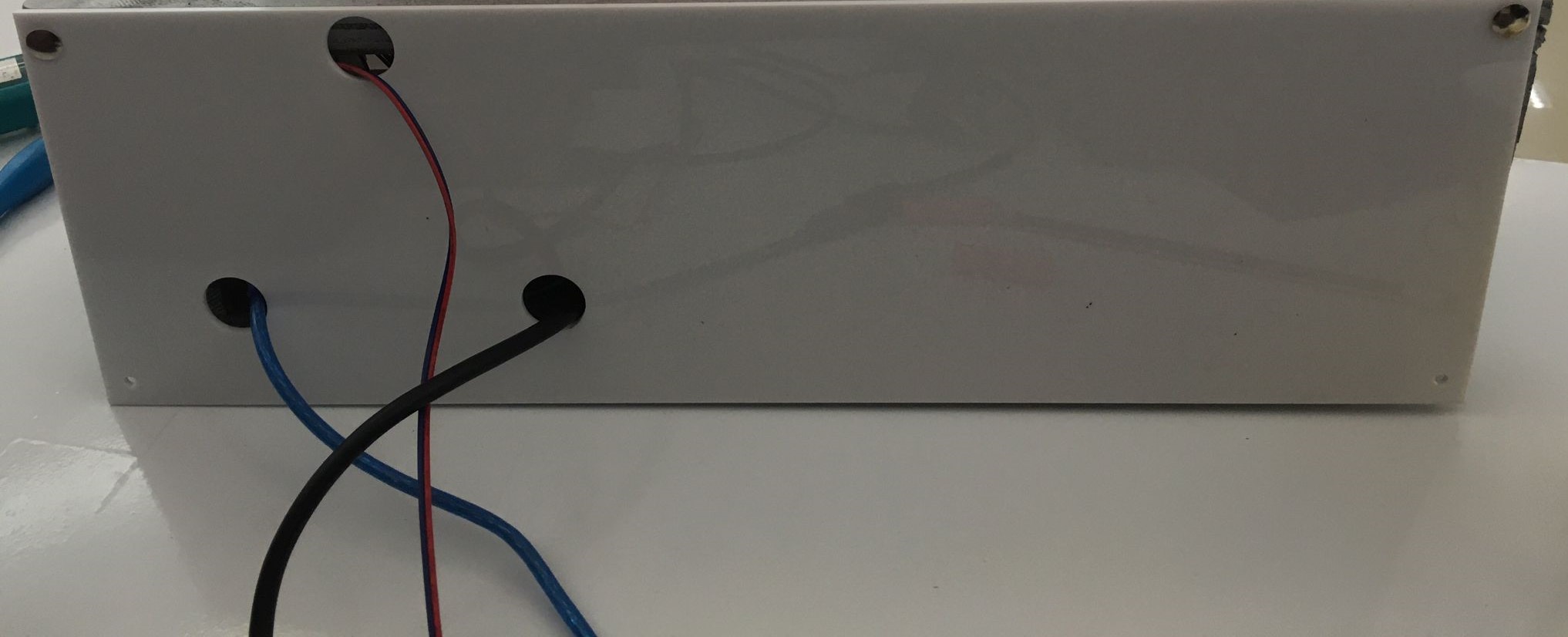
Back view:
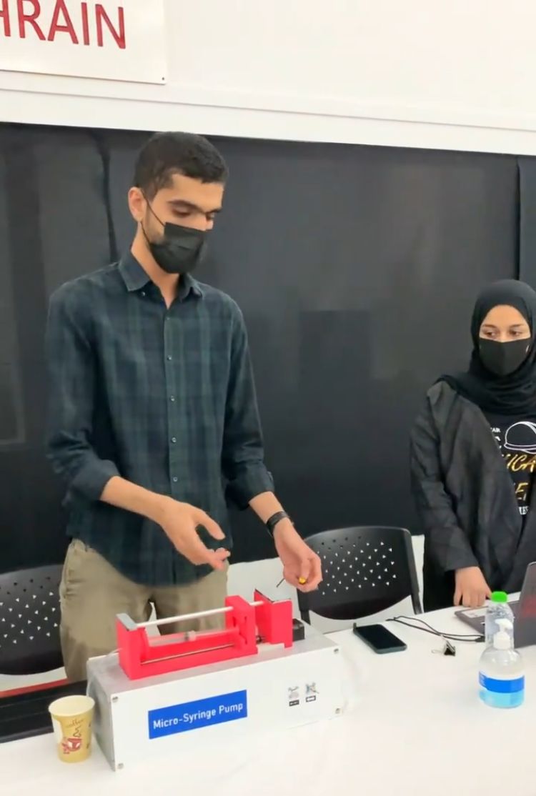
Finally, this picture illustrates the usage of the microsyringe pump in the exhibition which yielded satisfactory results: