7. Embedded programming
This week I worked on Enbedded programing on an Arduino nano microcontroller that is to be coded and given commands using different programs.
Arduino
Arduino Nano microcontroller boards are widely used in various fields like robotics and embedded systems that are discussed in this section. It is considerably small and can be considered as a flexible microcontroller as it can be used for various applications. This Arduino Nano micro controller is mainly based on ATmega328p, coming with old and new versions.
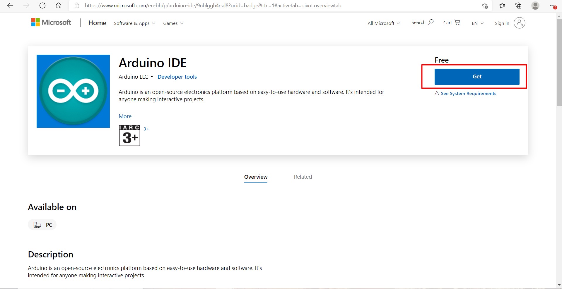
Firstly, both the arduino program and the driver are downloaded and installed in the laptop. Default settings for both installation procedures were followed. The links for both the driver and the arduino will be provided below. Here are pictures for the installation page: Arduino:
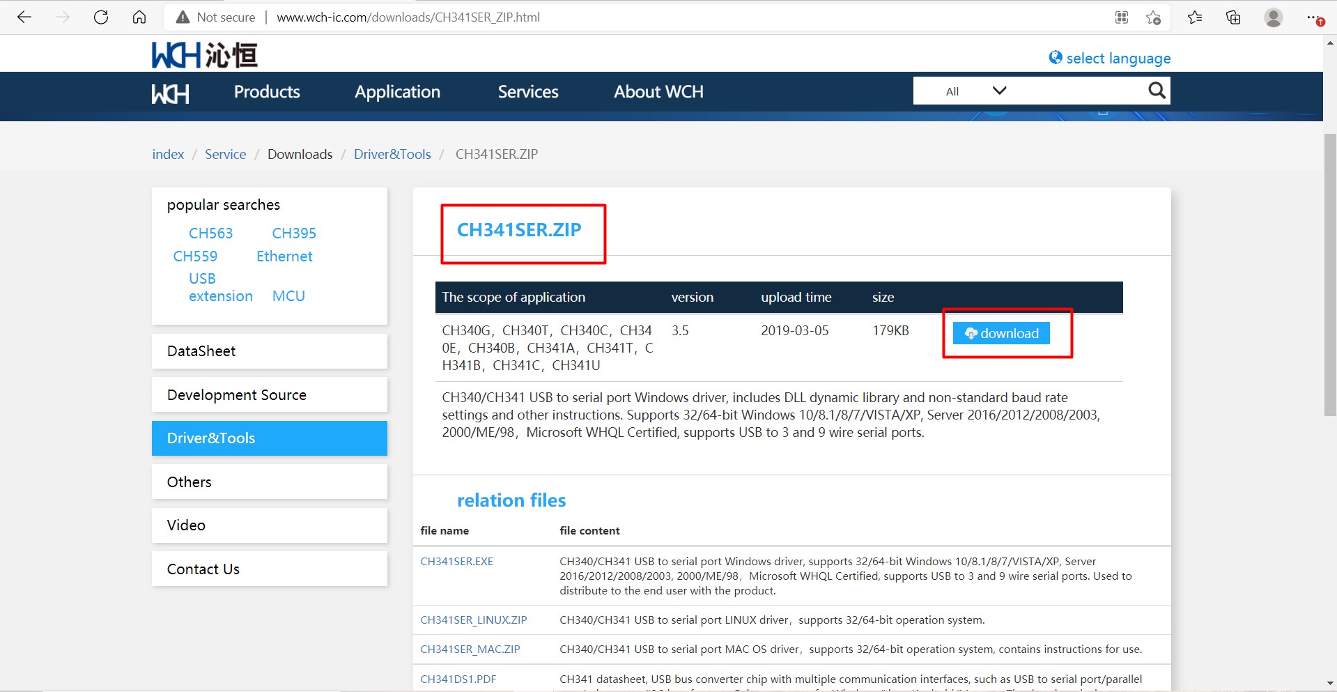
Driver:
Forthermore, the arduino nano microcontroller is constructed mainly of the following parts as shown below:
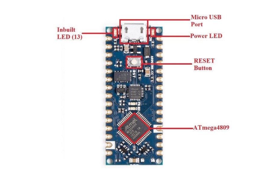
The inbuilt LED is represented (connected) by the pin 13 (if used in arduino) or the built in function, it can me manipulated by HIGH as on and LOW as off.
The reset button is used to reset the board and read the code from the beginning.
Power LED is used as an indicator whether the microcontroller is conneced to a power source or not as it will light up when connected.
The micro USB port is mainly utilized to power up the microcontroller.
Finally, the Atmega microchip is the mother of the microcontroller, as it features most of the technoligies of the microcontroller that enables it to run the commands.
The pins of the arduino nano microcontroller each has a specified purpose and specifiaction in which is some scenarios, it is required to use specific pins.
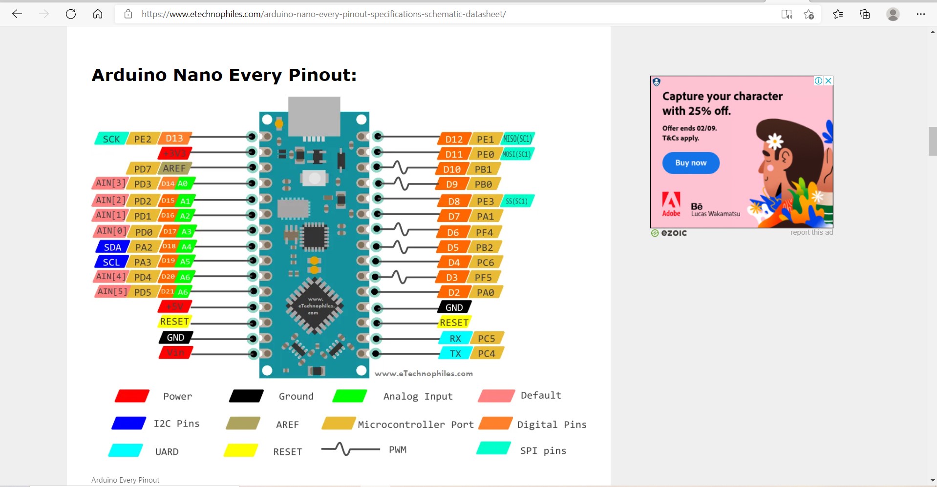
For example, the servo motor requires the utilization of a PWM (Pulse-Width Modulation) pins as it is the methodoligy at which the servo motor works (This is further explained in the input and output assignment). As a result, the pins used for the servo motor are restricted to the PWM pins. The previously put image describes the different types of pins which are described in the pinout datasheet.
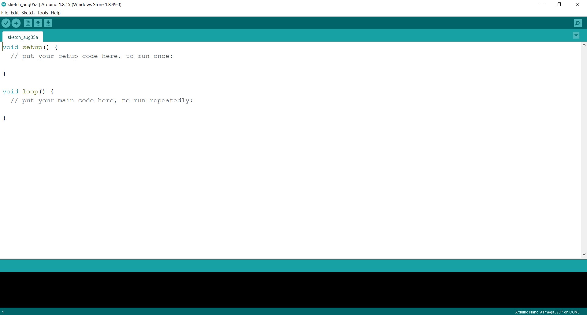
Arduino is the program used to command and give instructions to the microcontroller (Arduino nano). Arduino IDE is launched. Arduino would be the first out of the two coding programs to be used. The following page will show:
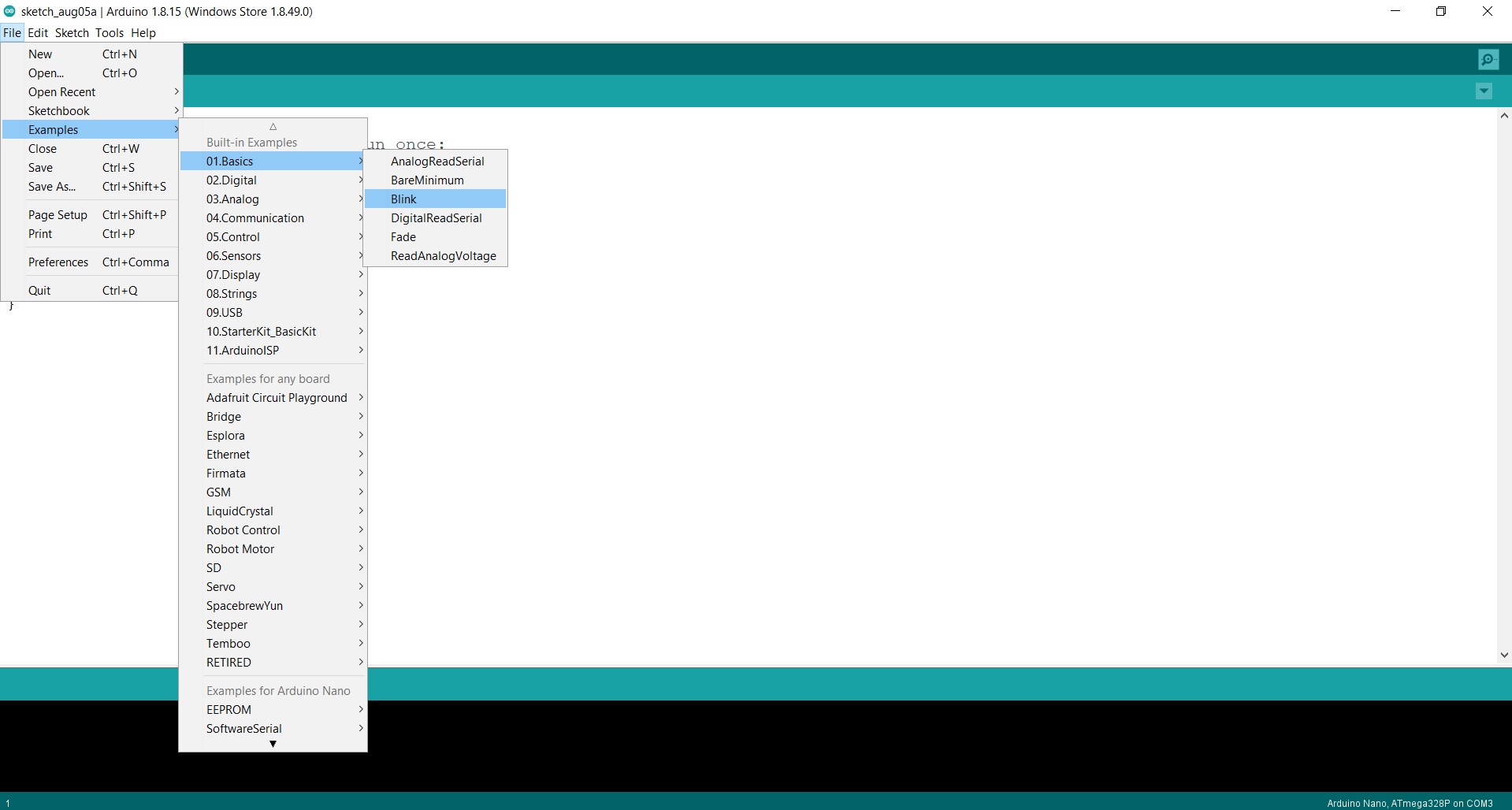
Then, the blink example will be implemented through the following procedure:
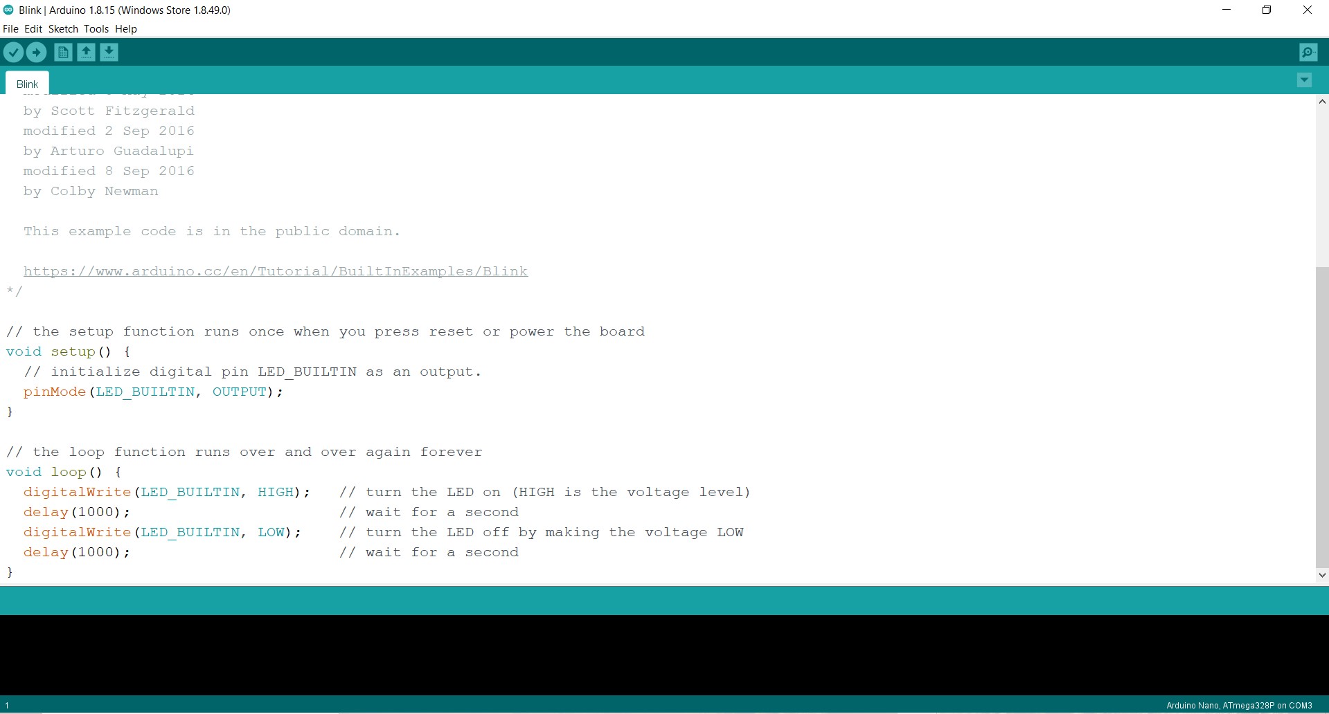
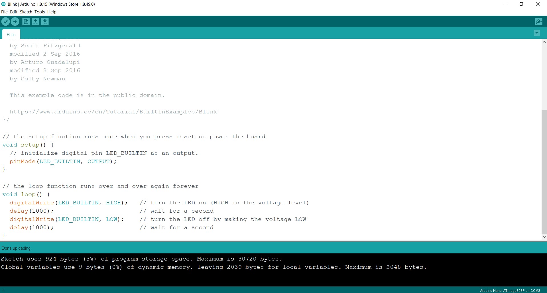
The code for the blink example will show up:
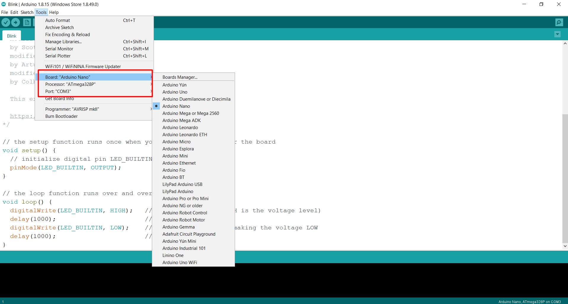
The arduino nano chip is put at the follwoing settings:
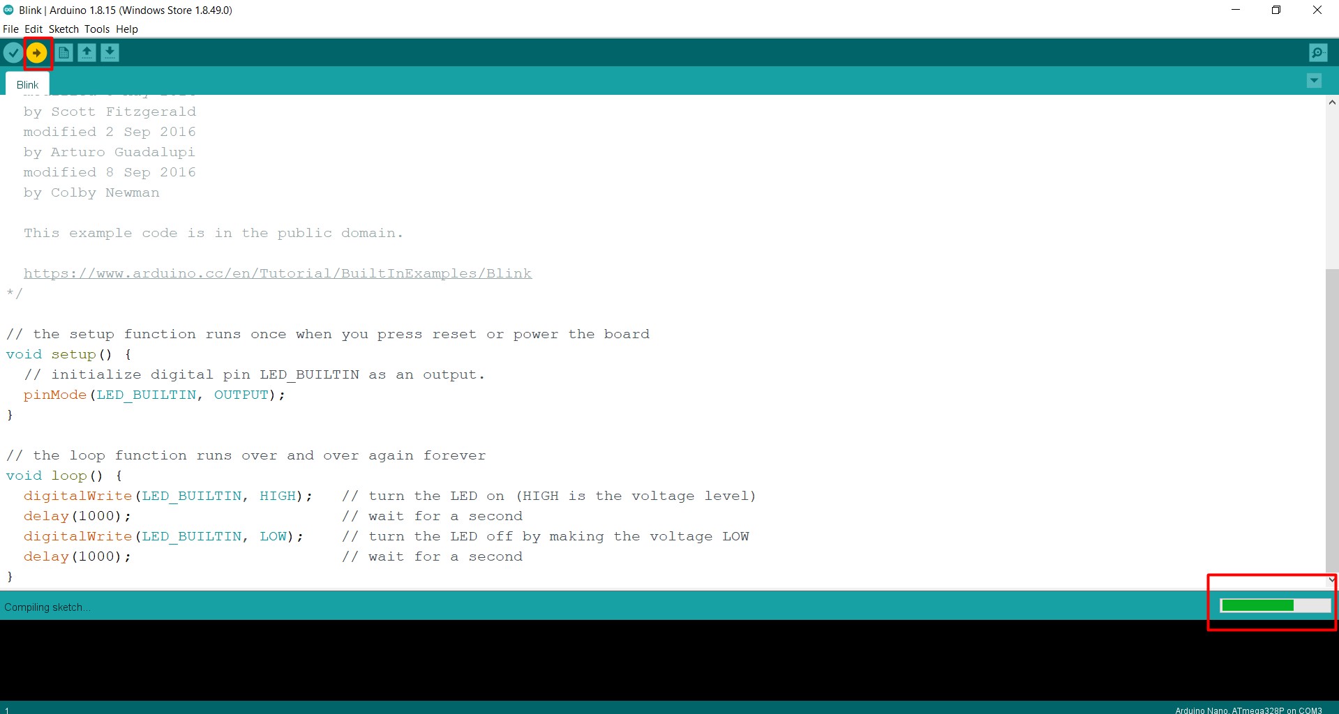
After the chip is set, upload the blinking commaned to the chip:
After uploading is done, you will notice the microcontroller is blinking with a delay of one second:
Note: the working procedure of the blinking code is explained in the easy mode section..
Easy mode
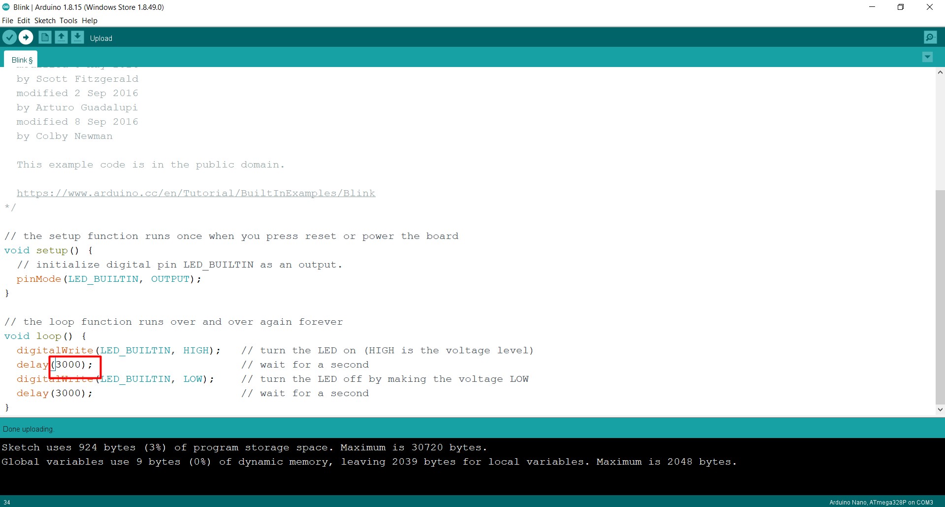
For the easy mode, to alternate the delay time, simply just the following numbers to change the delay time (each 1000 is one second):
As we can see, the code is mainly utilizing the built in function to manipulate the LED light of the microcontroller which is the (LED_BUILTIN) command which is assigned as an output from the microcontroller with the (pinMode) command as illustrated. This command is put in the void setup where the functions wanted to be run once are put there, as defining would be run once. Later on, within the void loop section, where the commands that are going to be run repeatidly are placed, the (digitalwrite) command is used to guide the specified variable (LED light) actions, where the HIGH indicates that the LED light would be on and the LOW would indicate that the light is off. Separating between them with each high and low with a delay to notice the changes. Each second is equvalent to 1000 in the arduino. Finally, upload the new settings and the microcontroller should look like this:
Medium mode
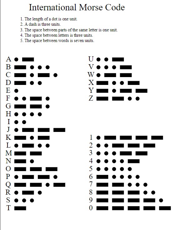
For the medium mode challenge, a morse code using arduino will be constructed to show the word “DANGER”. First of all, a picture of the morse code that is to be used to make the word is provided below:
The following code is constructed to give the word danger in the form of the morse code:
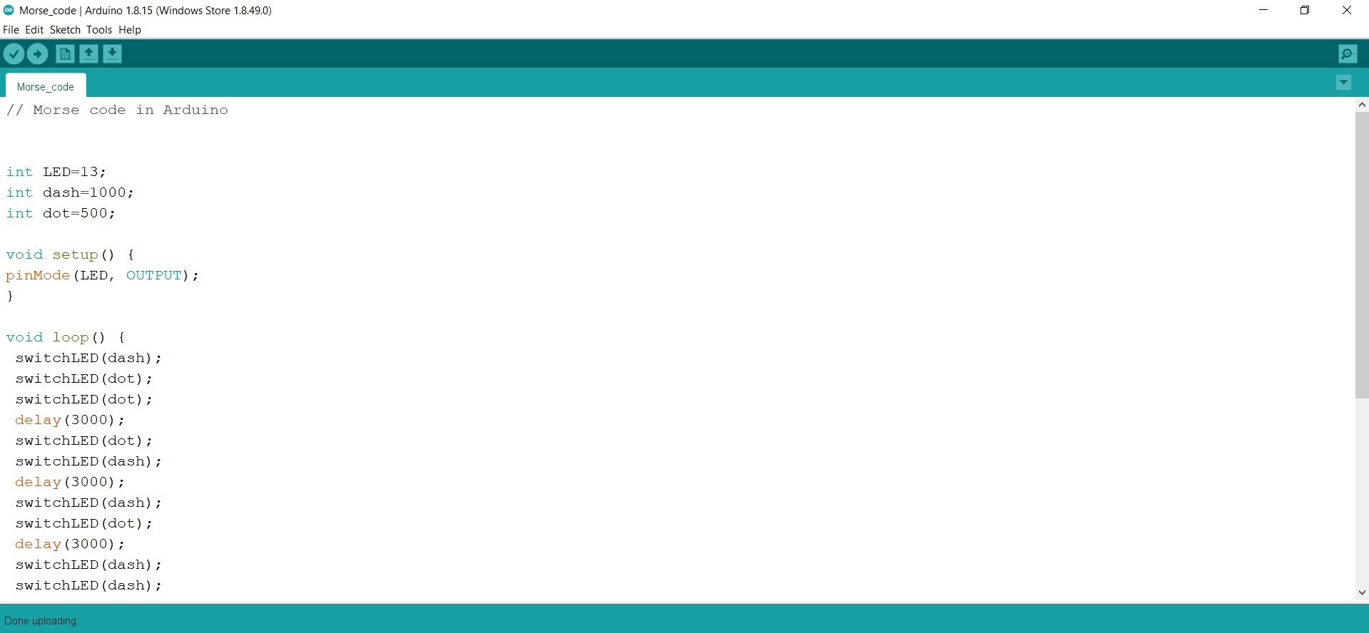
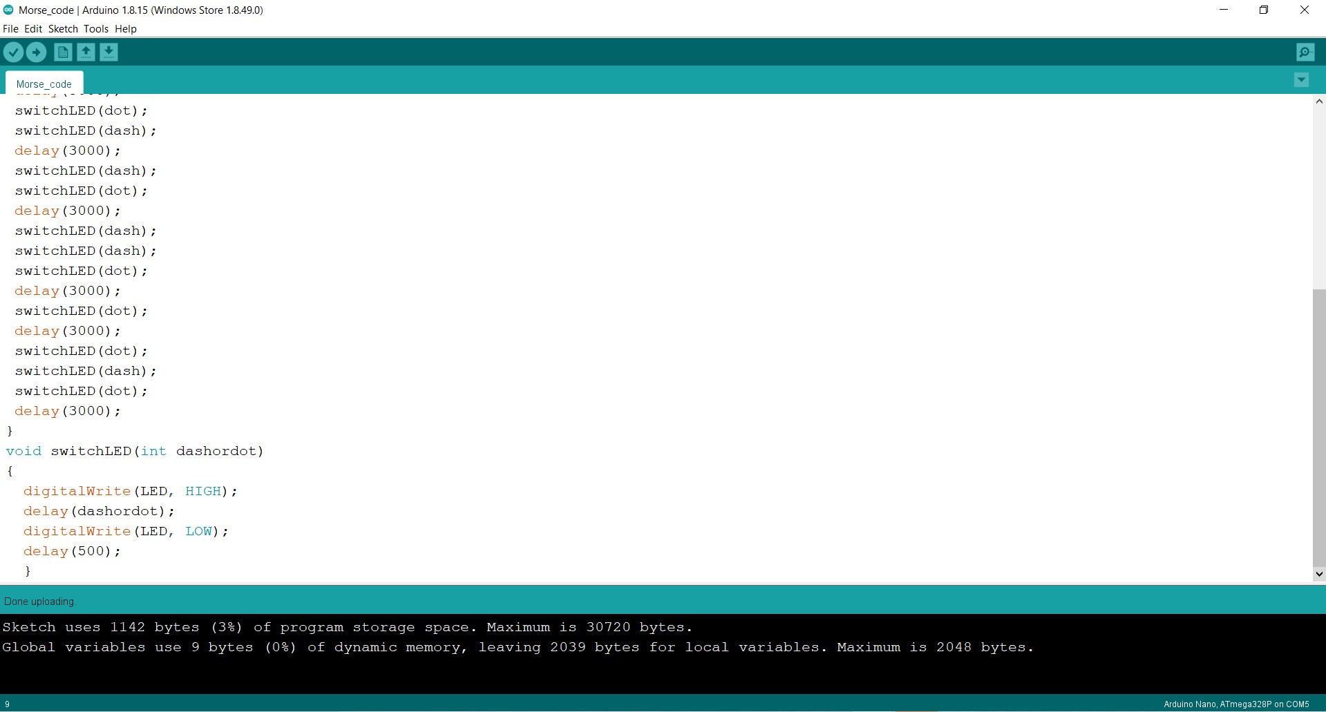
Firstly, both the dash and the dot were defined as specified (the dash being 1000 and the dot being 500, which represents the light staying on for one second for the dash and half a second for the dot). Here, a different approach to define the LED light on the microcontroller is used, where instead of using the built in function to use the light, a variable was equated to 13 which is the value representing the LED light. Then, the same commands used to guide and give actions to the LED light were used in the void setup. After that in the void loop section, the switch command was used on the LED light (which is defined here as LED) to switch it between dash and dot based on the assigned letter, for example, the D letter was presented by a dash, dot, dot sequence, which was coded as switchLED(dash) once followed by switchLED(dot) twice. This was repeated for each letter of the word DANGER, each letter separated by a delay of 3 seconds for the reciever to analyze each word and come out with a proper conclusion. Finally, the void switch was utilized in order to command the LED light to turn on for the duration of dash or dot based on the previous command, and turn off between each command of dash or dot for half a second.
The same morse code will be replicated in another coding program.
Visual Studio Code
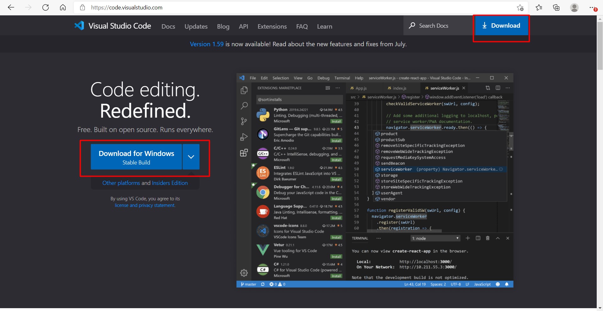
Visual Studio Code is considered a viable code editor that can be, with the proper extensions, utilized like the arduino ptogram to run codes giving commands to the microcontroller. To begin with, Visual Studio Code is downloaded as follows with the default settings:
This is the home page of the Visual Studio Code:
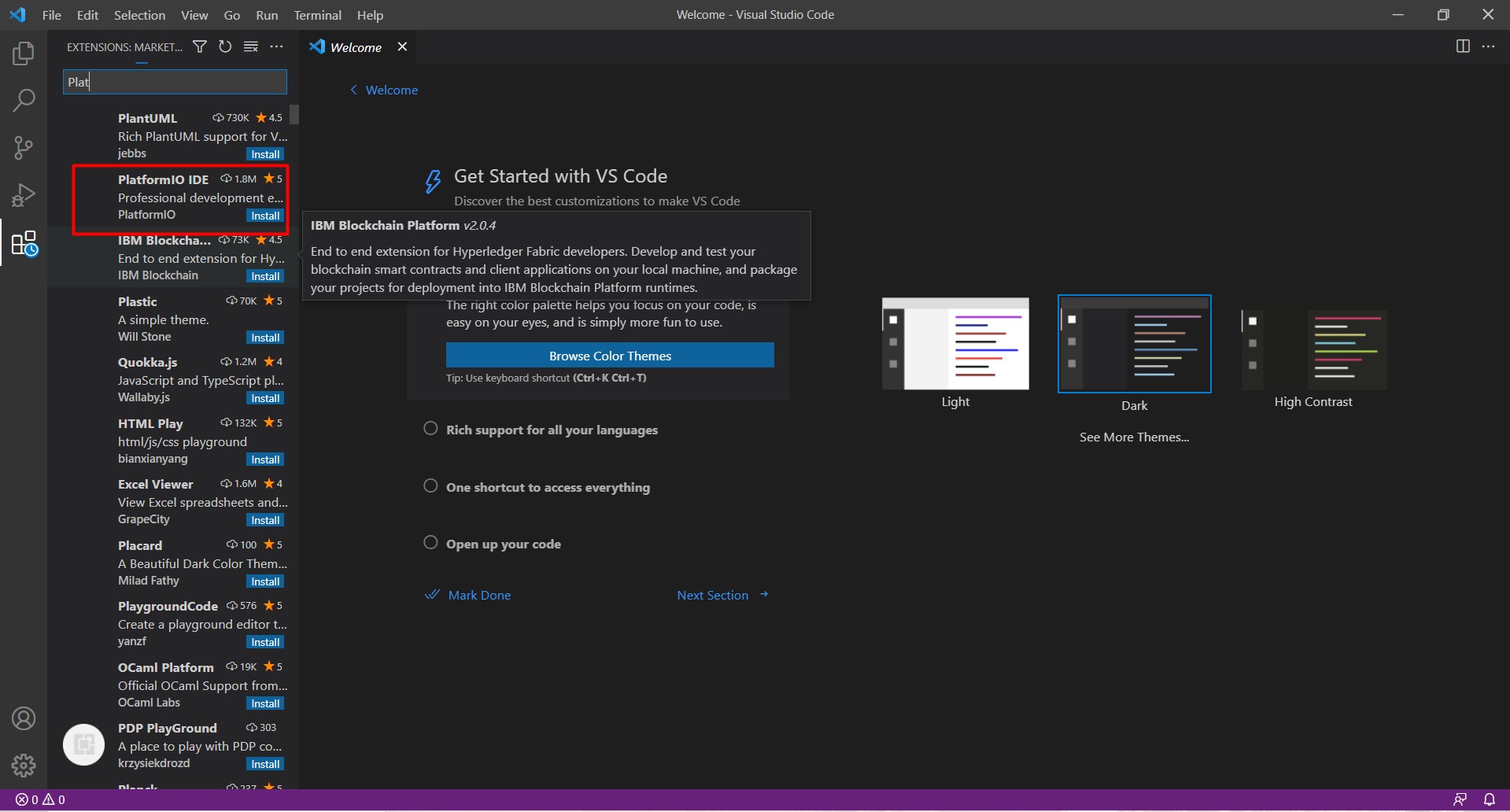
In order to sync the Arduino codes and make the Visual Studio Code analyze the Arduino boards pretty well, extensions were installed and adjusted in order to make this possible. The PlatformIO IDE extension is installed in order to sync and understand the Arduino code, the extension is installed as follows:
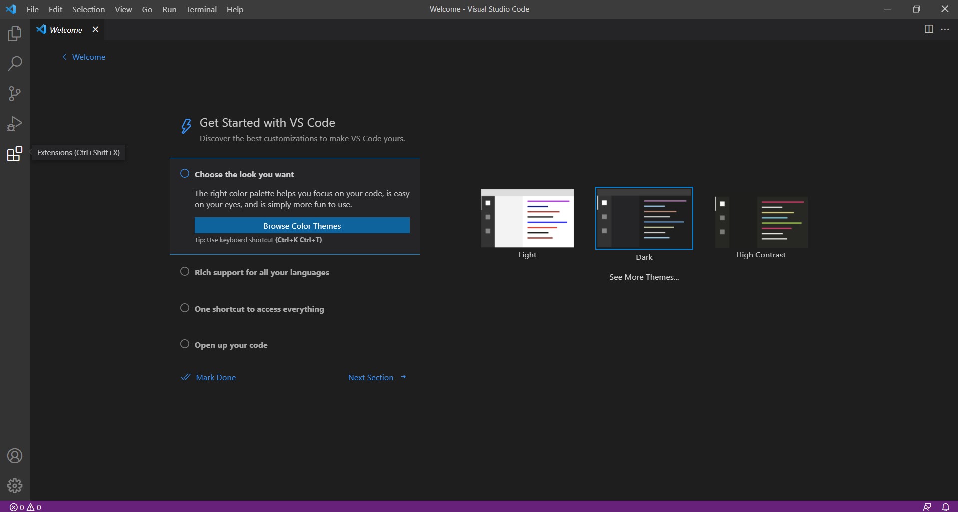
Go to the extension section:
Search and install PlatformIO IDE
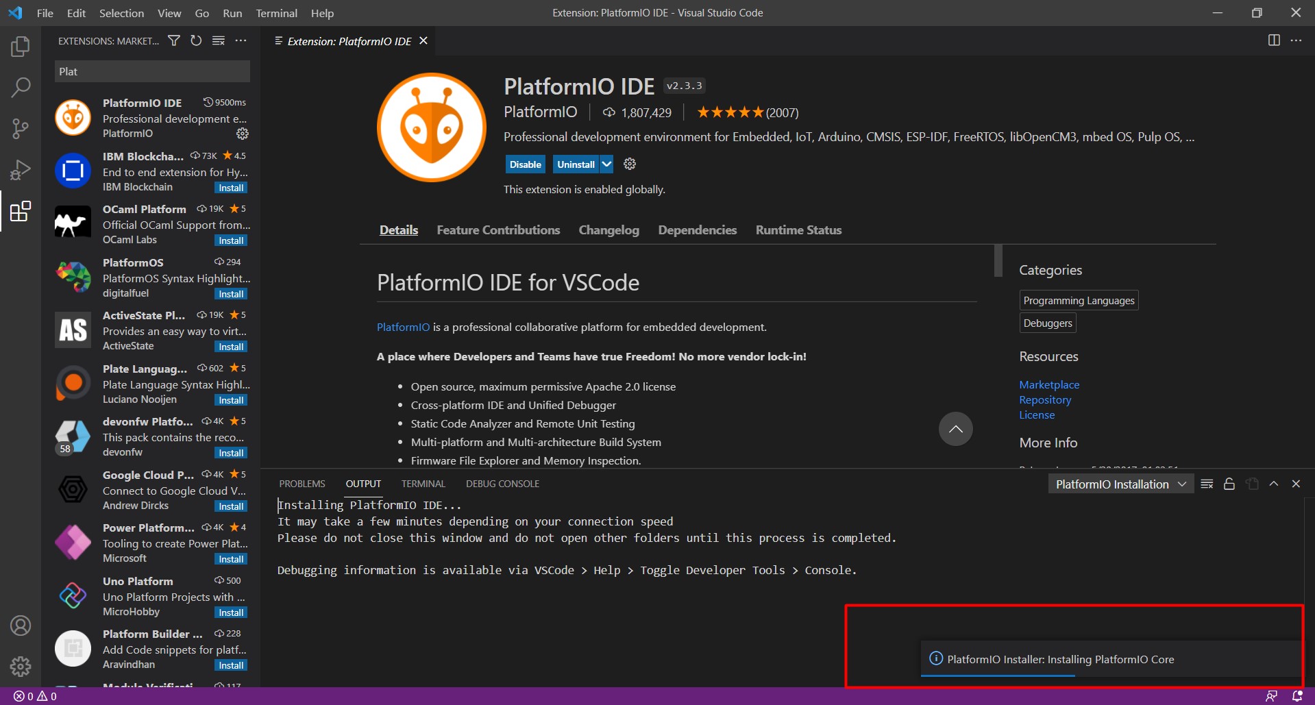
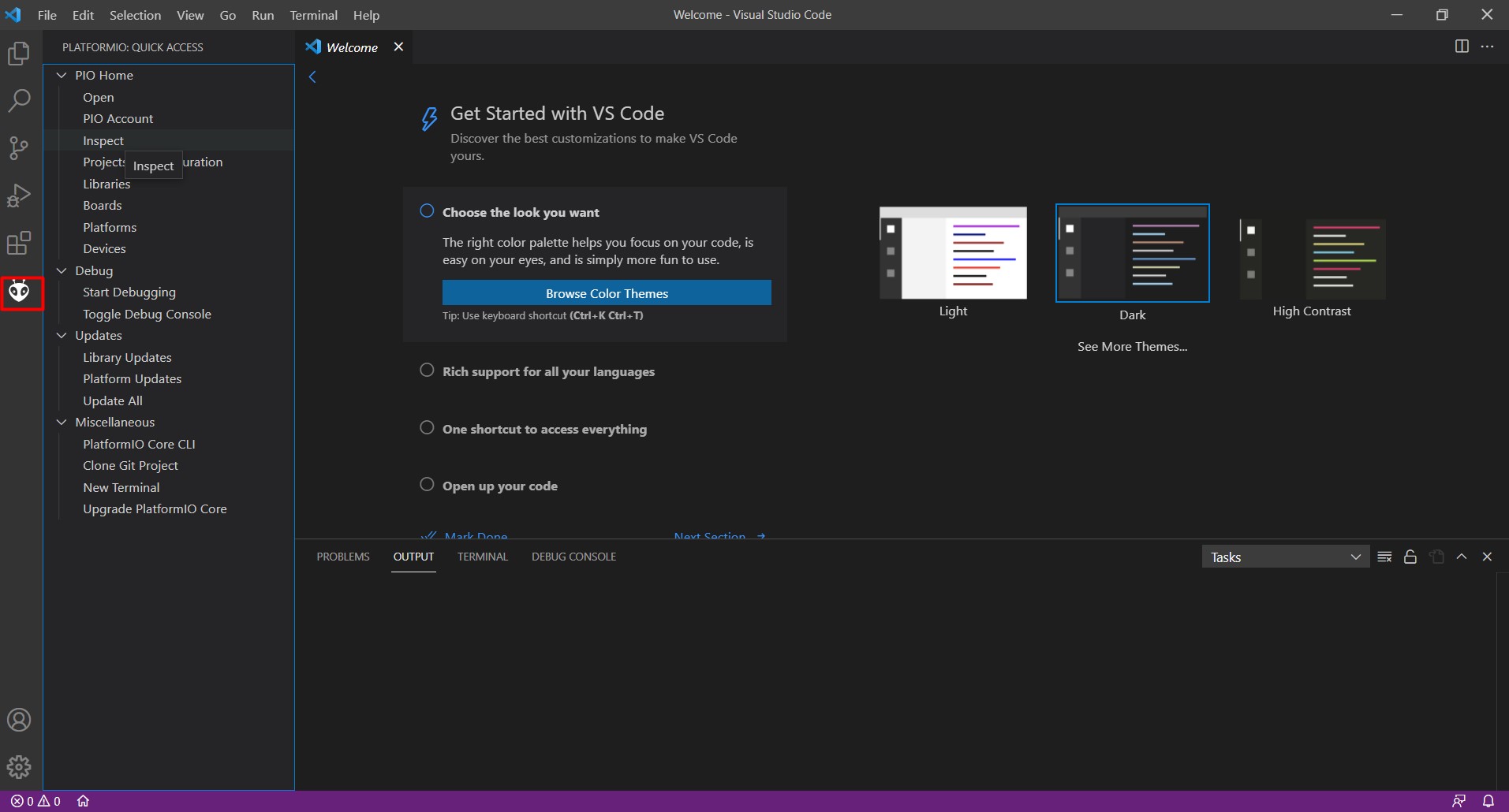
After installation, reset the program. Then this icon will be visible in he main menu:
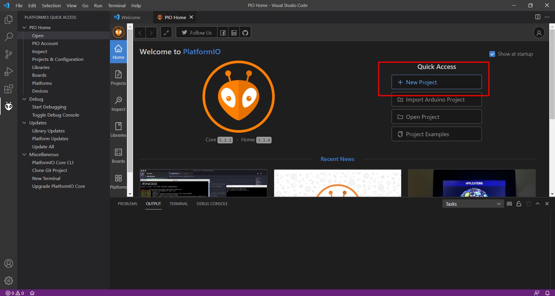
Press it and then select a new project
After selecting a new project, set the type of the arduino board:
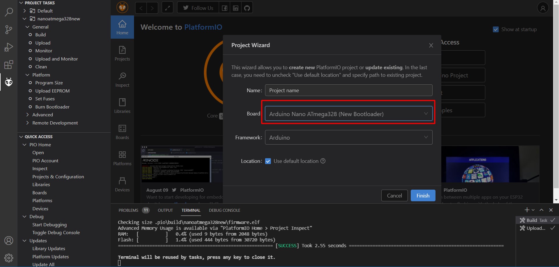
Now, accept the following:
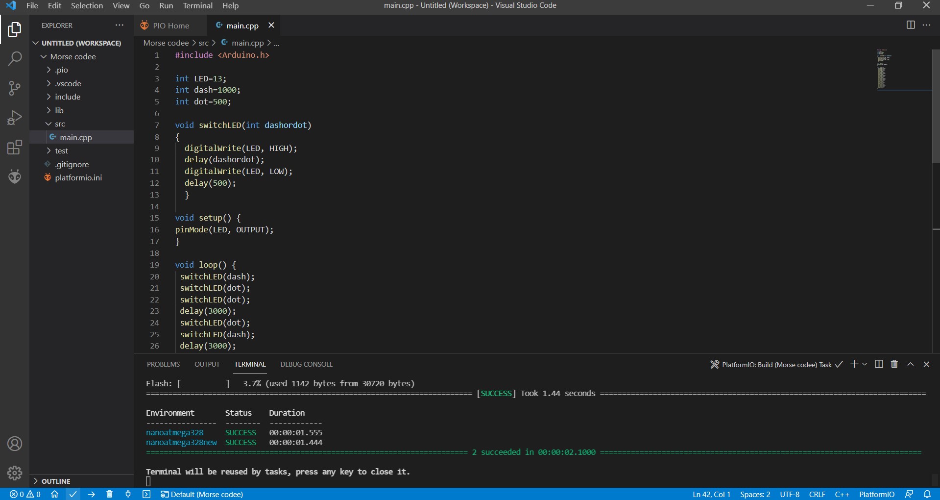
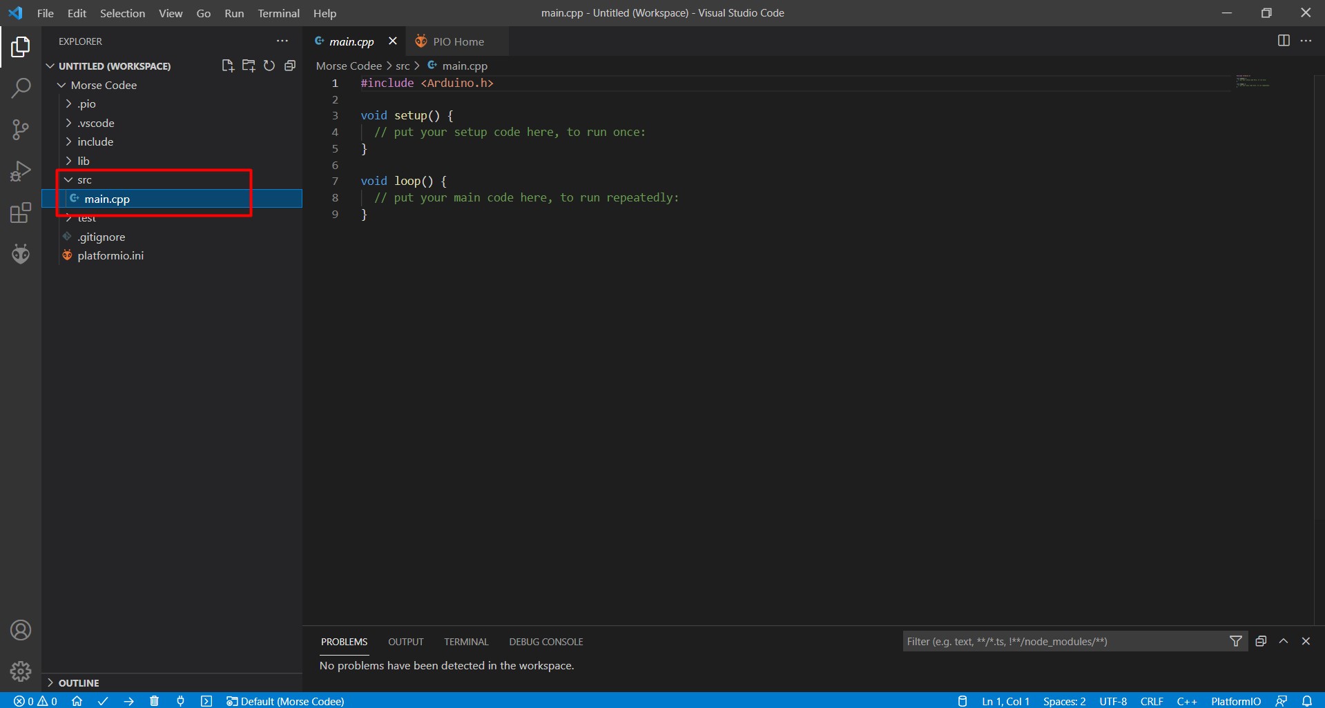
From the side tool bar, go to the main cpp, where you will put a copy of the already established Arduino code, with the include command on the top to ubderstand the arduino language.
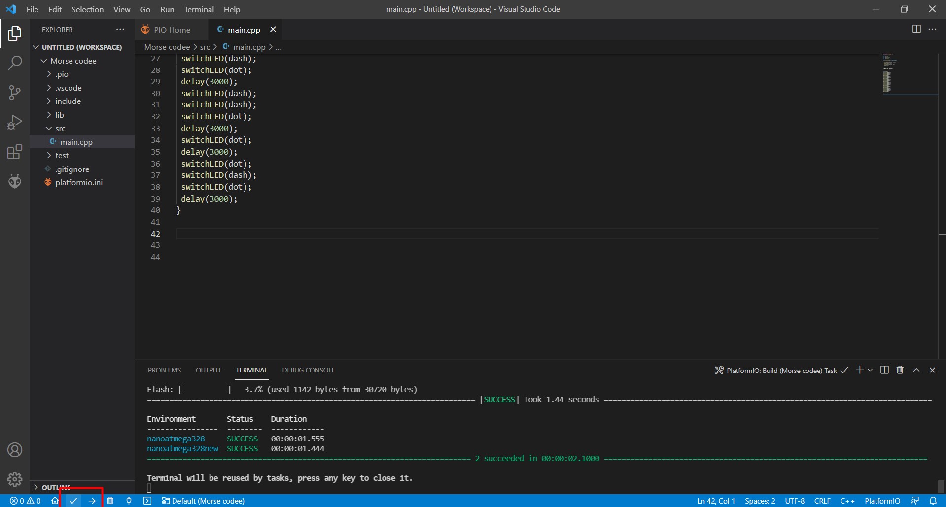
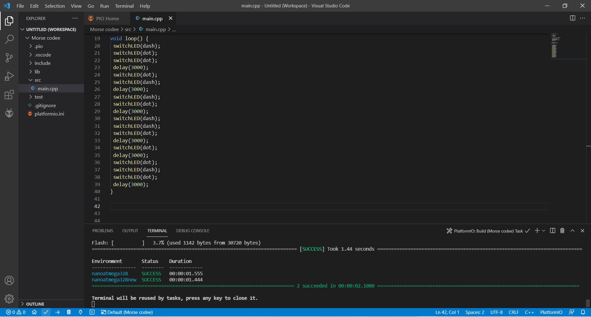
The switch command will be shifted upwards as in this program it needs to be defined prior to any upcoming usage:
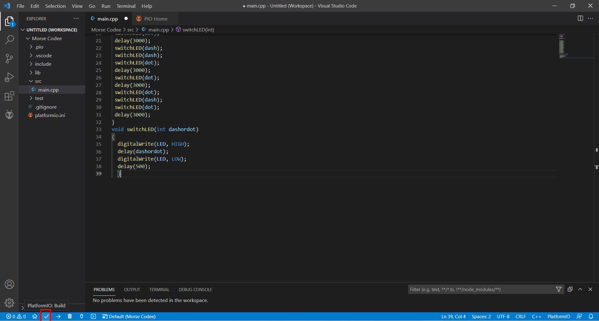
After that, building and uploading the code are done which will yield two successes as in the following pictures, which also shows the fnal code: