3. Computer controlled cutting
This week I worked on computer controlled cutting. I learned about two cutting techniques; Vinyl cutting and Laser cutting.
Vinyl cutting
First, the vinyl cutter was presented to us. We were shown the needles and the cutter operation was explained. After that, we learned about the software Cricut. We installed it on our computers and we were shown how to use it.
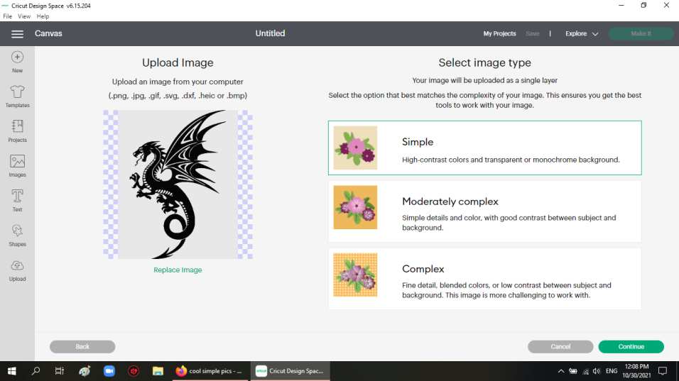
We then had to find pictures to make stickers with using the vinyl cutter. I used google to look up a cool photo of a dragon. I found it on this site
/pillow-covers-black-dragon.jpg.jpg)
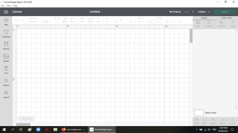
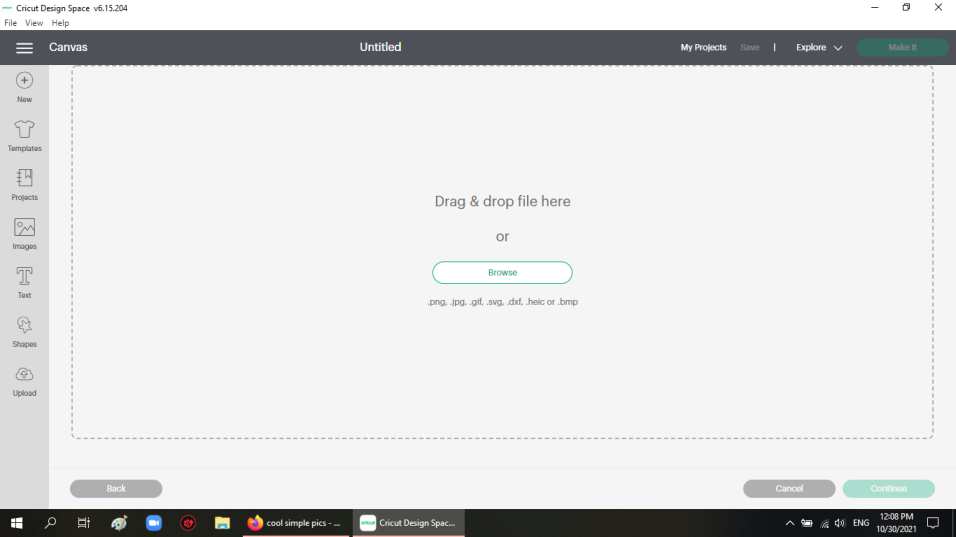
Then I opened Cricut and uploaded the photo
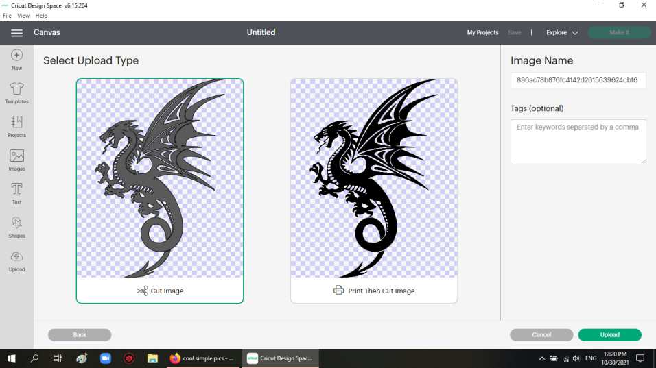
I chose the simple image option, since I thought it might be enough.
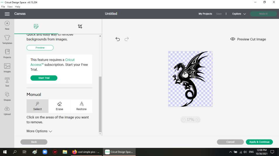
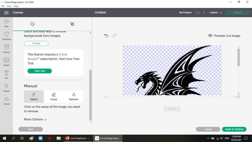
The next thing, was to remove the white background of the picture. this is done with a manual tool since I was using the free version of Cricut.
After that, I hit apply and continue which showed me a preview of the cut.
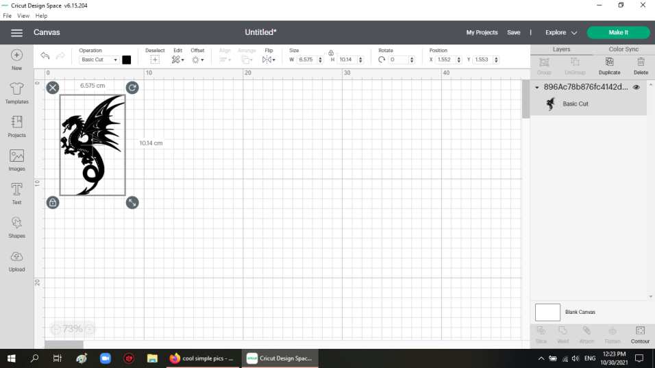
I then clicked upload, then I was able to resize the cut to the dimensions I want.
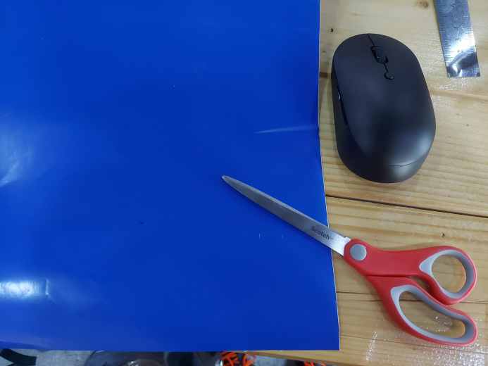
I then had to choose the paper which I was to use and I had to take a big enough size for my cut, but not too much so I don’t waste materials.
Then came the moment of truth, I connected my computer to the machine using a usb cable, and then I clicked make it on the Cricut software. and the following screen was shown
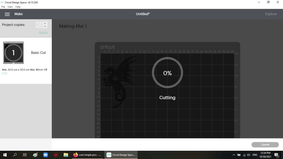
and the machine started the cutting operation
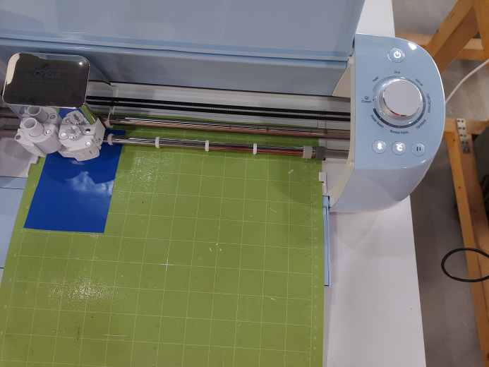
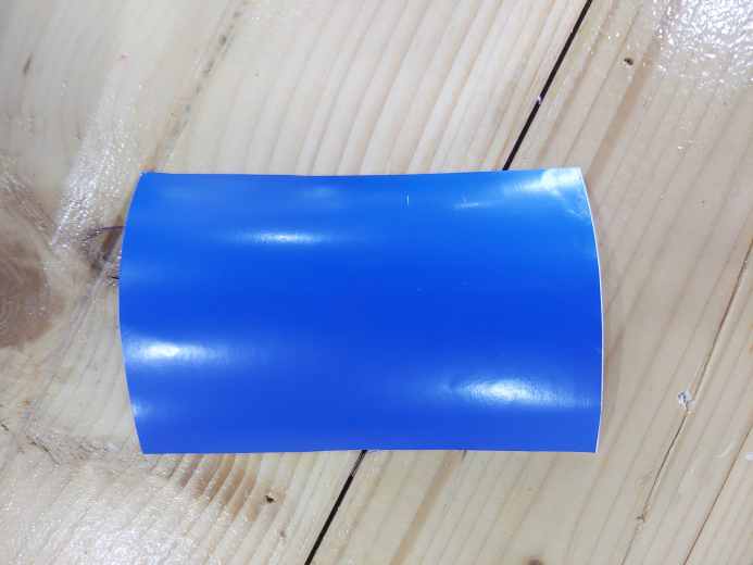
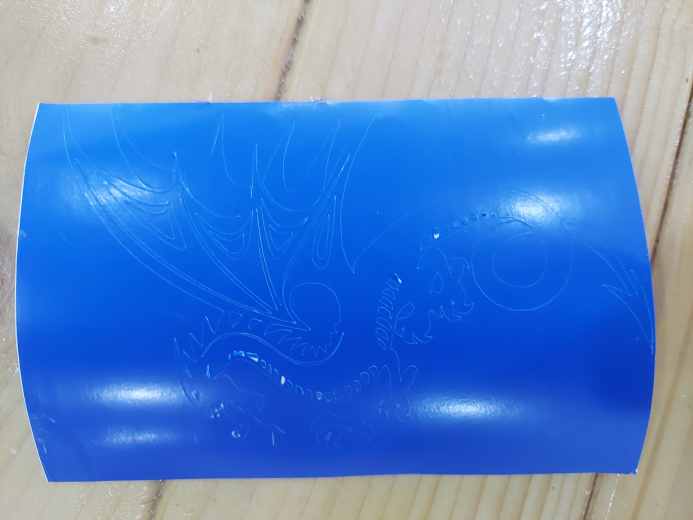
The cutting operation went smoothly, and this was the result
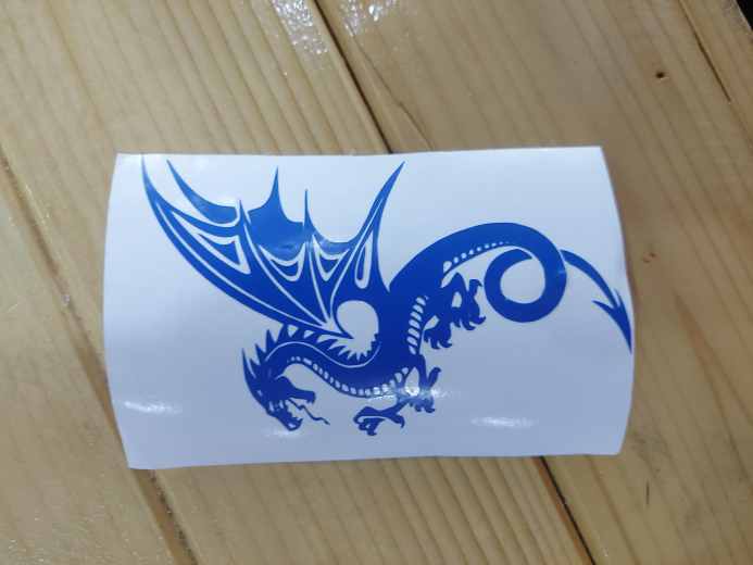
The next step was to remove the excess pieces and get the sticker. this was done both by hands, by tape, and by a pair of tweezers. This is the final result:
Laser cutting
This week, we also worked on cutting with a laser cutting machine. The machine can be used to cut or engrave on various materials. The material we used was cardboard. This was chosen because it was abundantly available. There were two parts to this week’s work, group work and individual work.
Group work
Our group was divided into two smaller groups. The first group learned how to operate the laser cutting machine, and tested out different cutting speed and power settings, to figure out the settings that gave the best cut for our cardboard material. The work can be found on Salman’s page. The second group worked on designing a sketch that looked like a comb, where the separation between the comb’s teeth was variant, so that we can figure out the separation that where a piece of our material can fit firmly. The work can be found on Kumail’s page.
Individual work
Our goal was to create a press-fit design using pieces that we design and cut by the laser machine. The design also had to have parametric variables, so that changing some values would change all the desired dimensions related to that parameter.
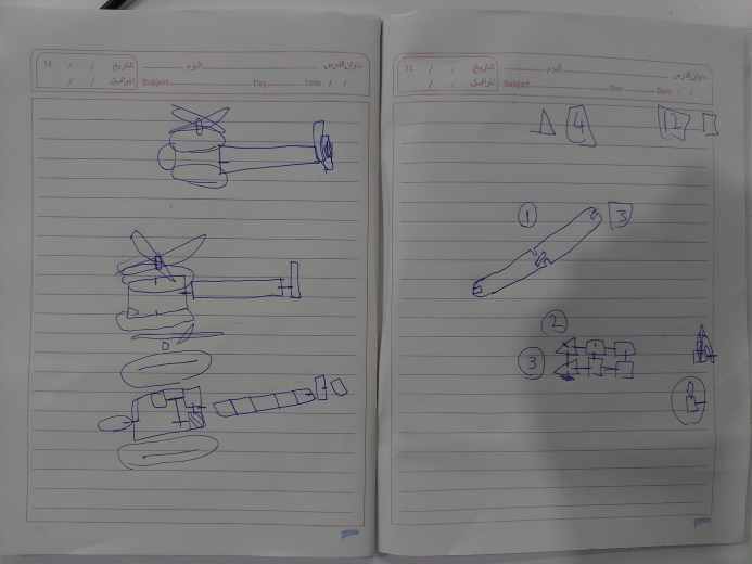
First, I had to come up with an idea for what I wanted my pieces to make up. I thought about making a plane, but then decided that a helicopter would be much cooler. I then proceeded to try to figure out the design of the pieces, I thought about using big pieces, then thought about using all small pieces. In the end, with some help, I decided to use both small and big pieces.
This is a rough sketch from the design stage
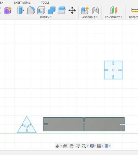
Then I went on and installed Fusion 360 to design the pieces with. I faced some difficulties with the software since I’ve never used it before, but with some help from instructors and some videos, I was able to get by. The pieces I designed were a long rectangle, a square, and a triangle. Each had some rectangular openings in the sides where I was going to connect the pieces together based on my design. To add the openings, I added rectangles on the desired sides and I cut off the undesired edges. I used the circular pattern tool to help duplicate the edges in a proper way to the desired sides. It was sometimes helpful, but I faced some issues where the more things than I wanted were copied and lines were on top of lines. Nevertheless, I was able to get over the hurdles and get the design right. The parameters I used were for the side lengths of the shapes and for the thickness of the rectangular opening, which was crucial to parameterise, so that it can be changed easily if the pieces fit too loose, or the openings were too small. I first used a thickness of 1.2mm for the openings.
Those are the pieces I designed
After that, I went on to cut my pieces so that I can test them, and determine whether or not the design was successful.
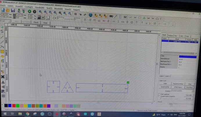
This is a pic of the test batch in the laser machine software before I cut them.
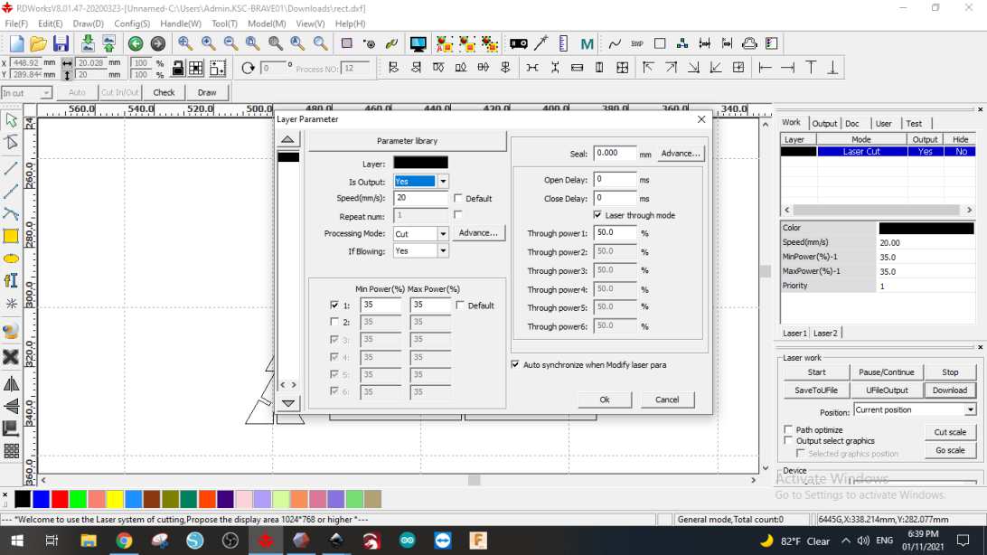
Those were the cutting settings. I used a speed of 20 and a power of 35.
After cutting the first pieces, I noticed that the pieces did not fit together well which meant the openings were too loose. Moreover, in the rectangular piece, the opening’s length was too big, which caused some weakness in the piece. I then went on and decreased the thickness parameter of the openings to 1mm, and the length of the openings in the rectangular pieces to increase its structural integrity.
After that, I cut the second batch, which I tried to fit together. Thankfully, the pieces fit firmly and then I was ready to cut all my pieces.
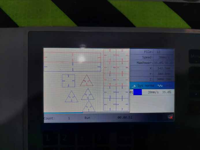
This is a picture from the laser machine, just before cutting.
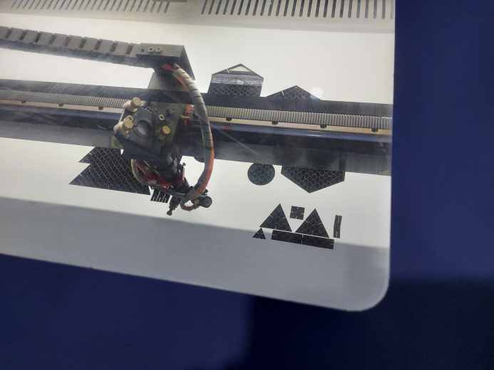
This is the laser while cutting

and those pieces are the result
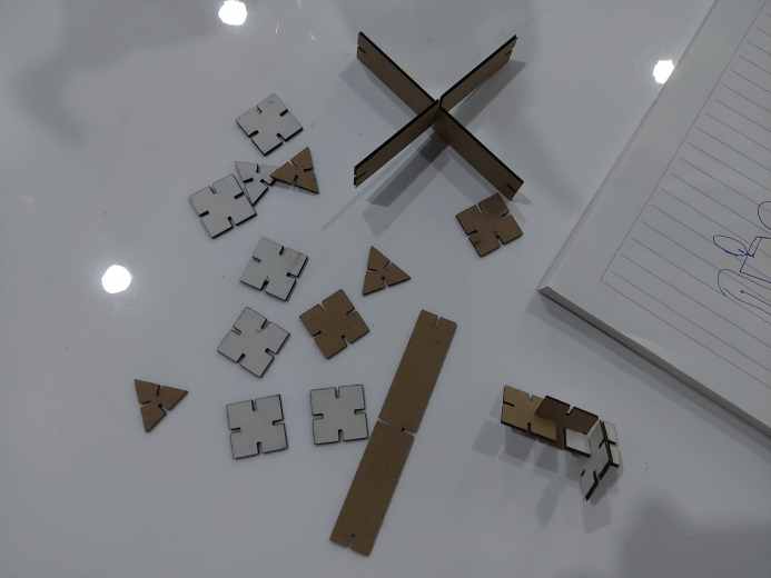
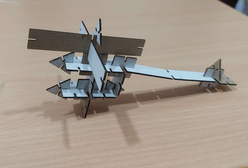
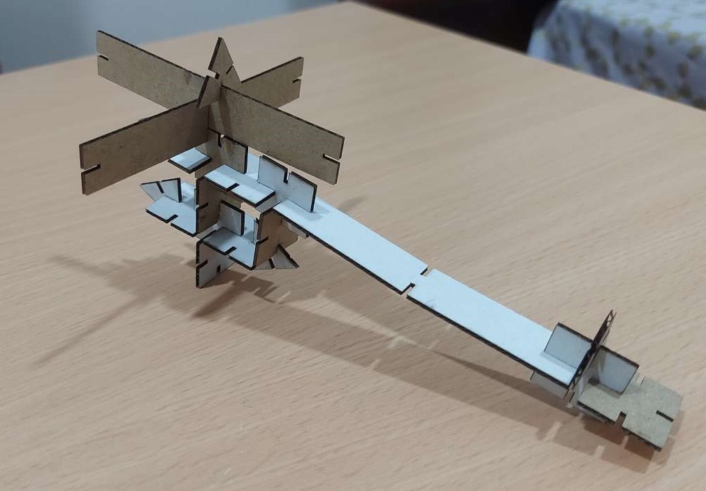
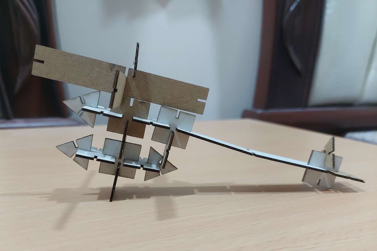
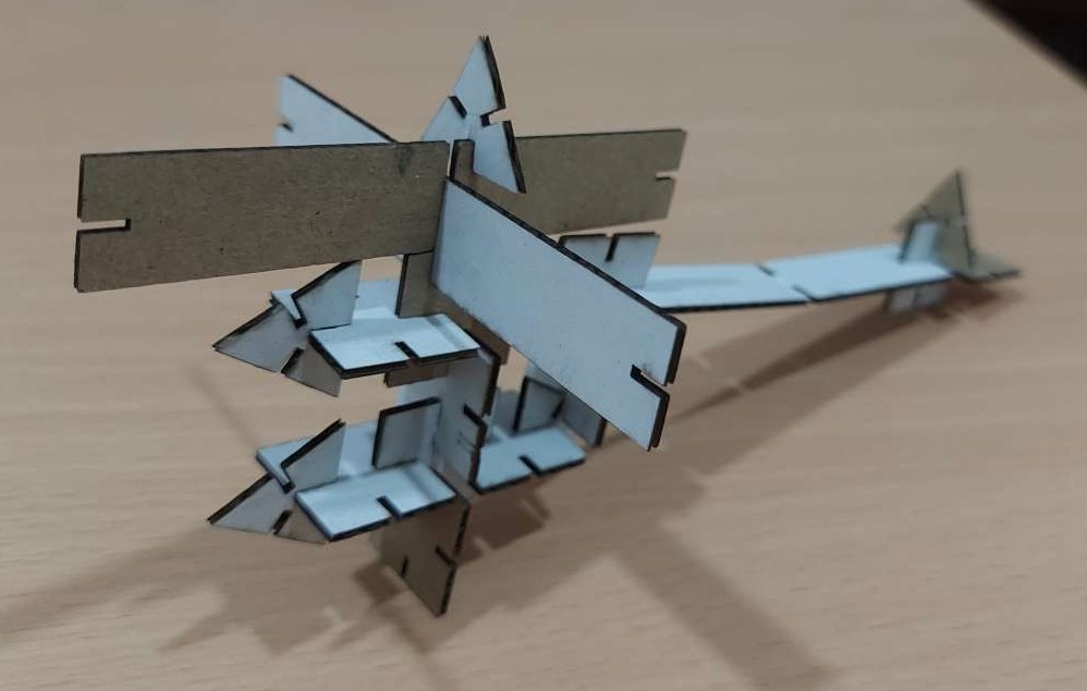
Finally, the moment has come. I started to put the pieces together to construct my press-fit helicopter. Piece by piece, until the helicopter was complete. The design used 3 rectangular pieces, 5 triangular pieces, and 12 square pieces.
These are some pictures of the final result
Design file
This is the design file for the pieces, for anyone who might want to replicate the work in the future.