3. Computer controlled cutting
Cutter machine
first of all I had to install the program :
The program that I used for this machine called circuit design space :
 You can install it from here
Working on the program :
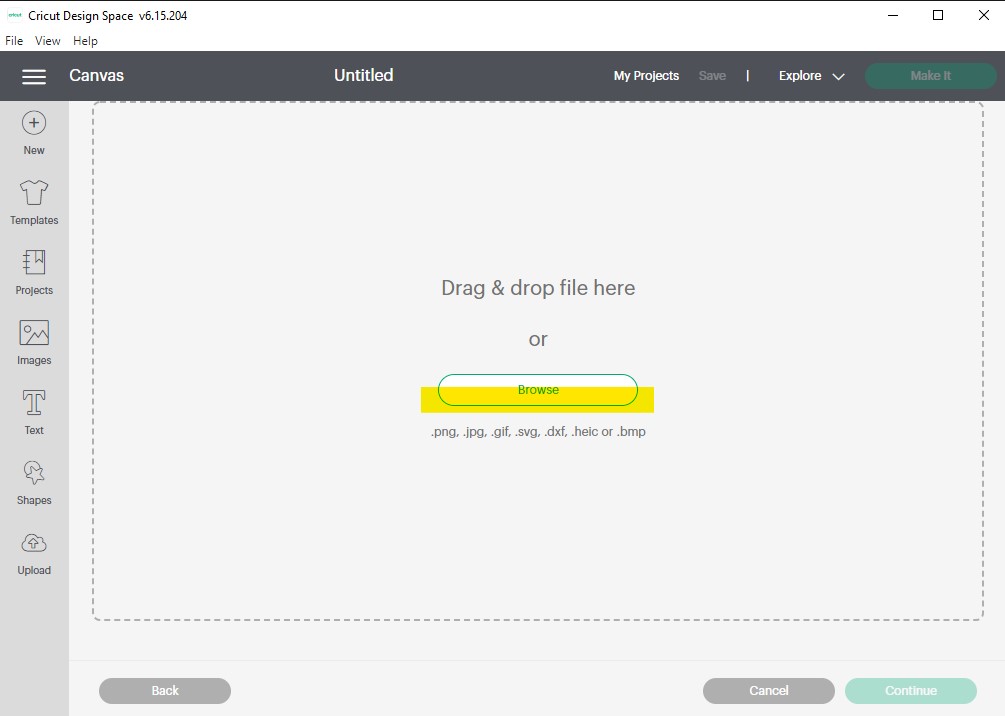
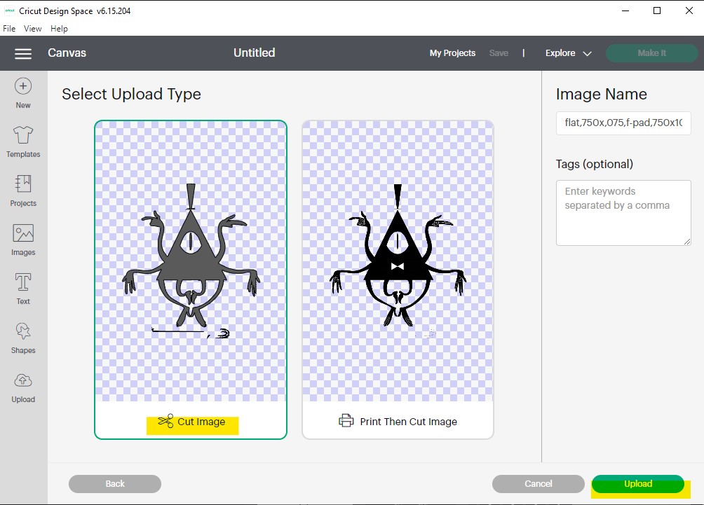
The interface of the program will be like :
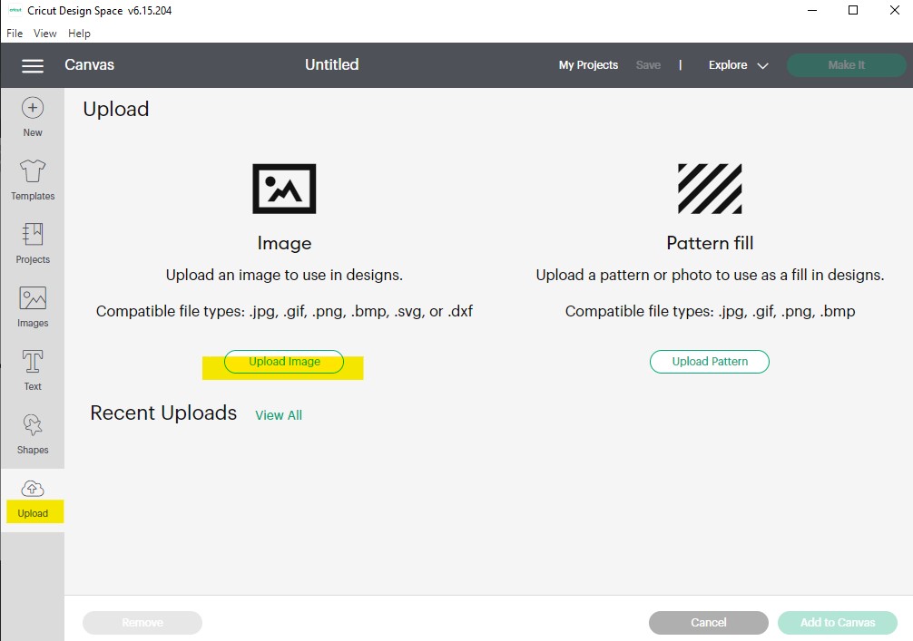
If you want to insert any image from the computer just click :
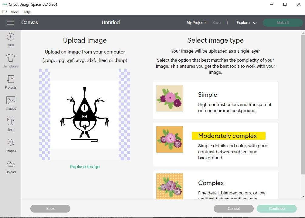
I chose this image for the first time :
 I took the image from this site
Now I chose the complexity of the image (the image which I chose was not so complex that is why I chose moderately complex )
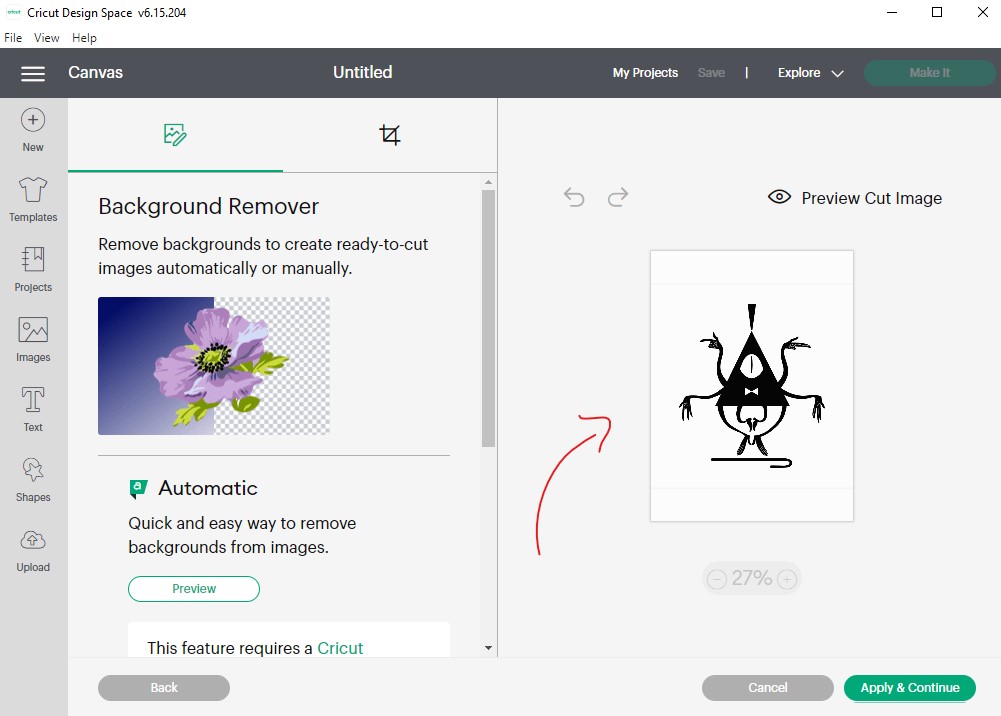
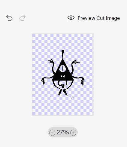
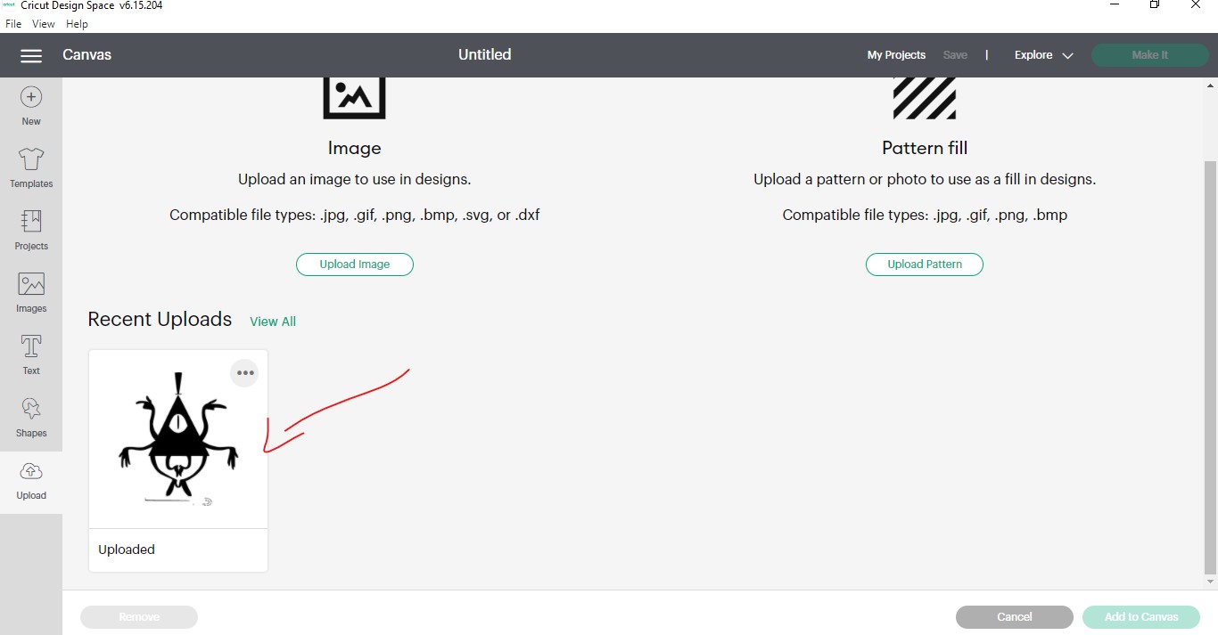
Now the image is ready just I hade just to upload the image to the machine :
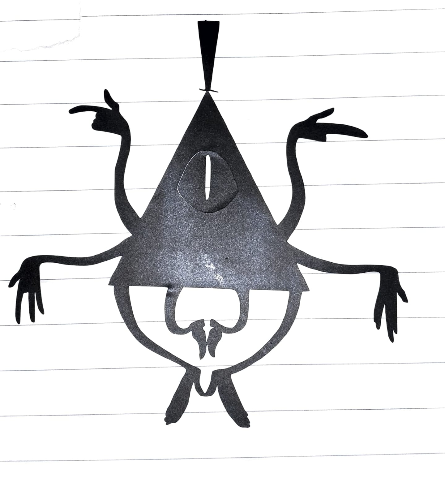
After the printing the sticker will be like :
Laser cutting machine program (group assignment)
First of all we had to draw or upload any shape in a program called RDWorks
and this program will link our project to the machine

working on Laser cutting machine
We drew a simple shape just to discover the program
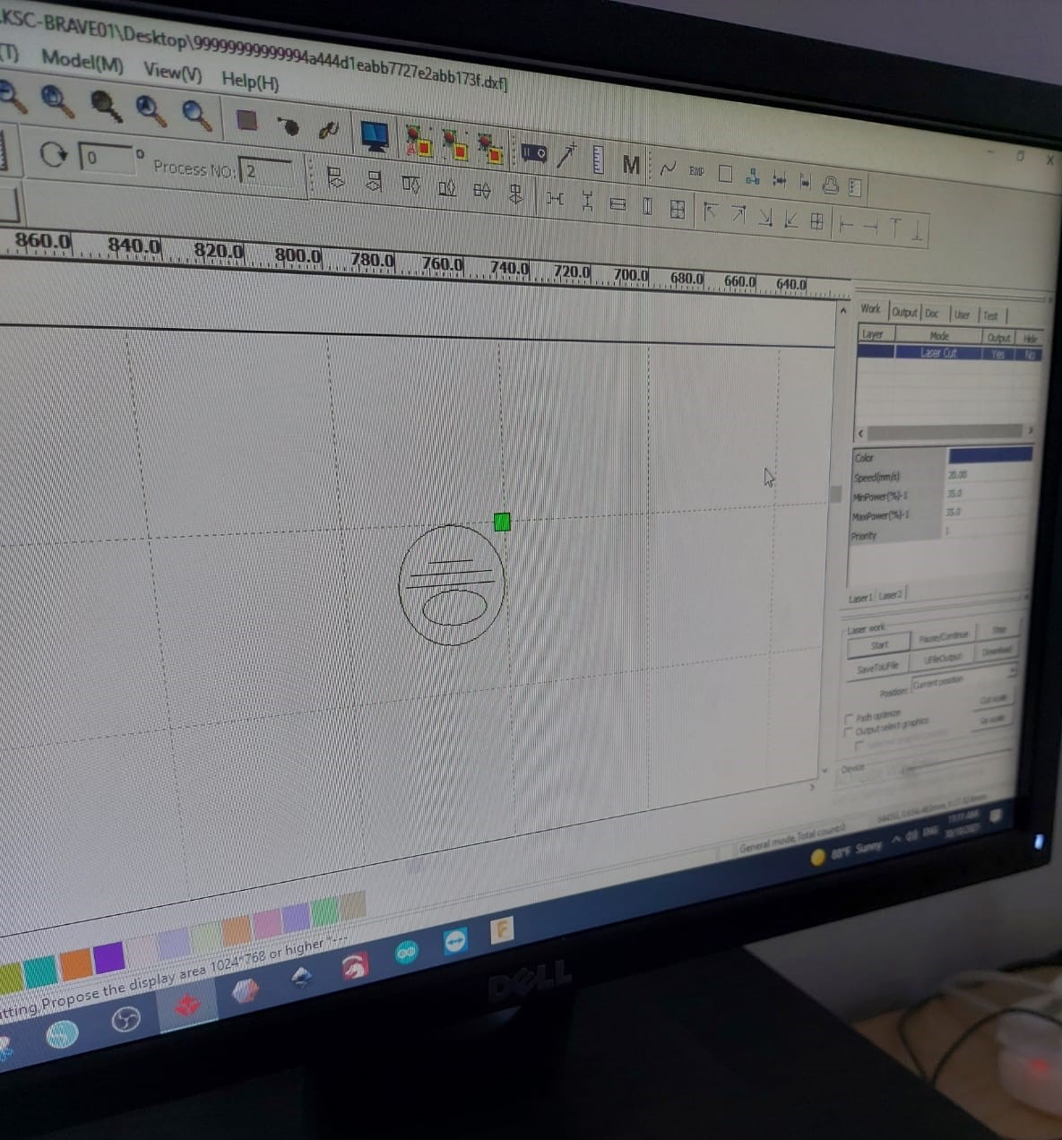
And we had then to select the shape that we would like to print and edit the setting of it
here we chose the speed at 20 mm/s and the power at 35w :
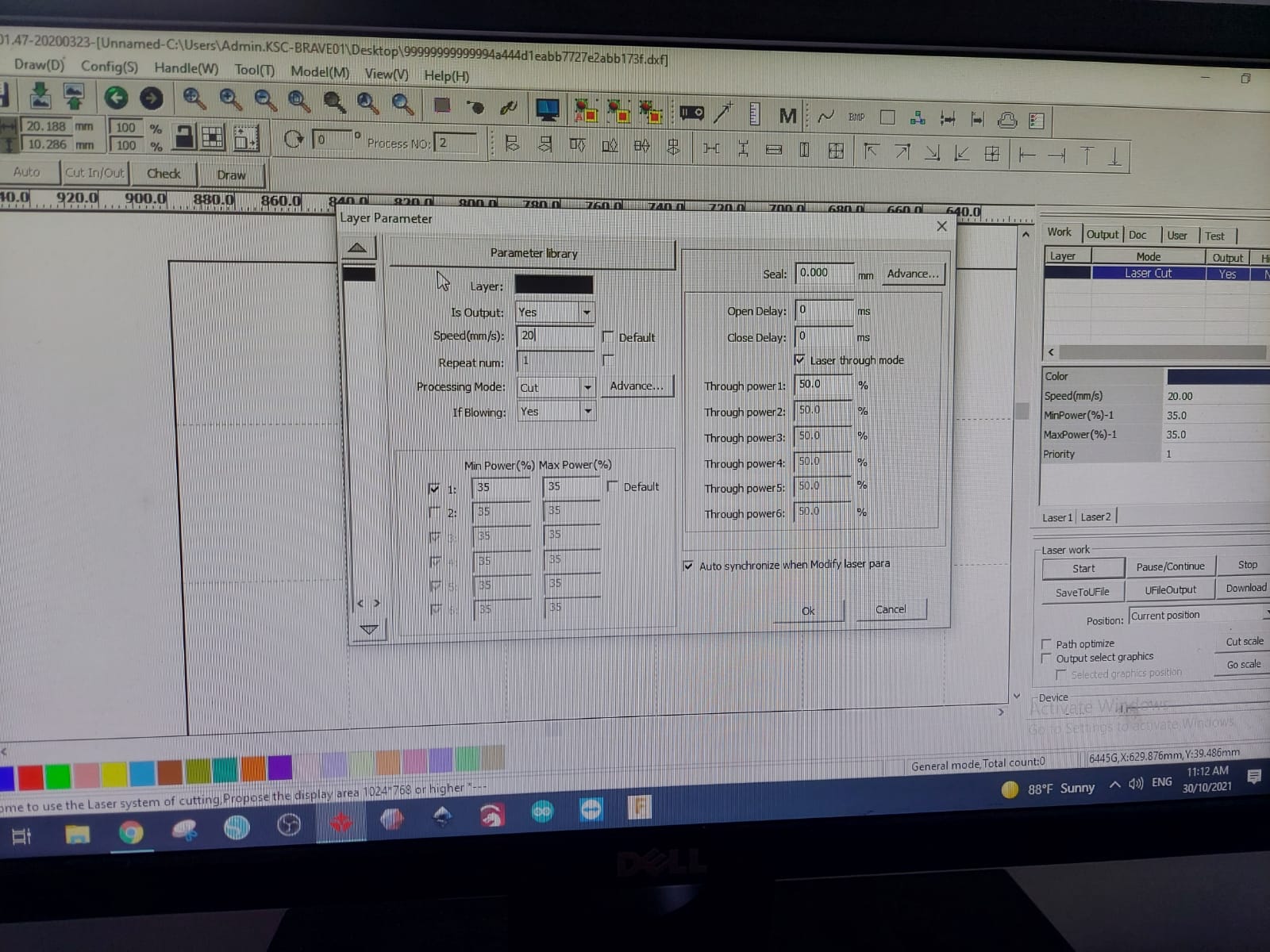
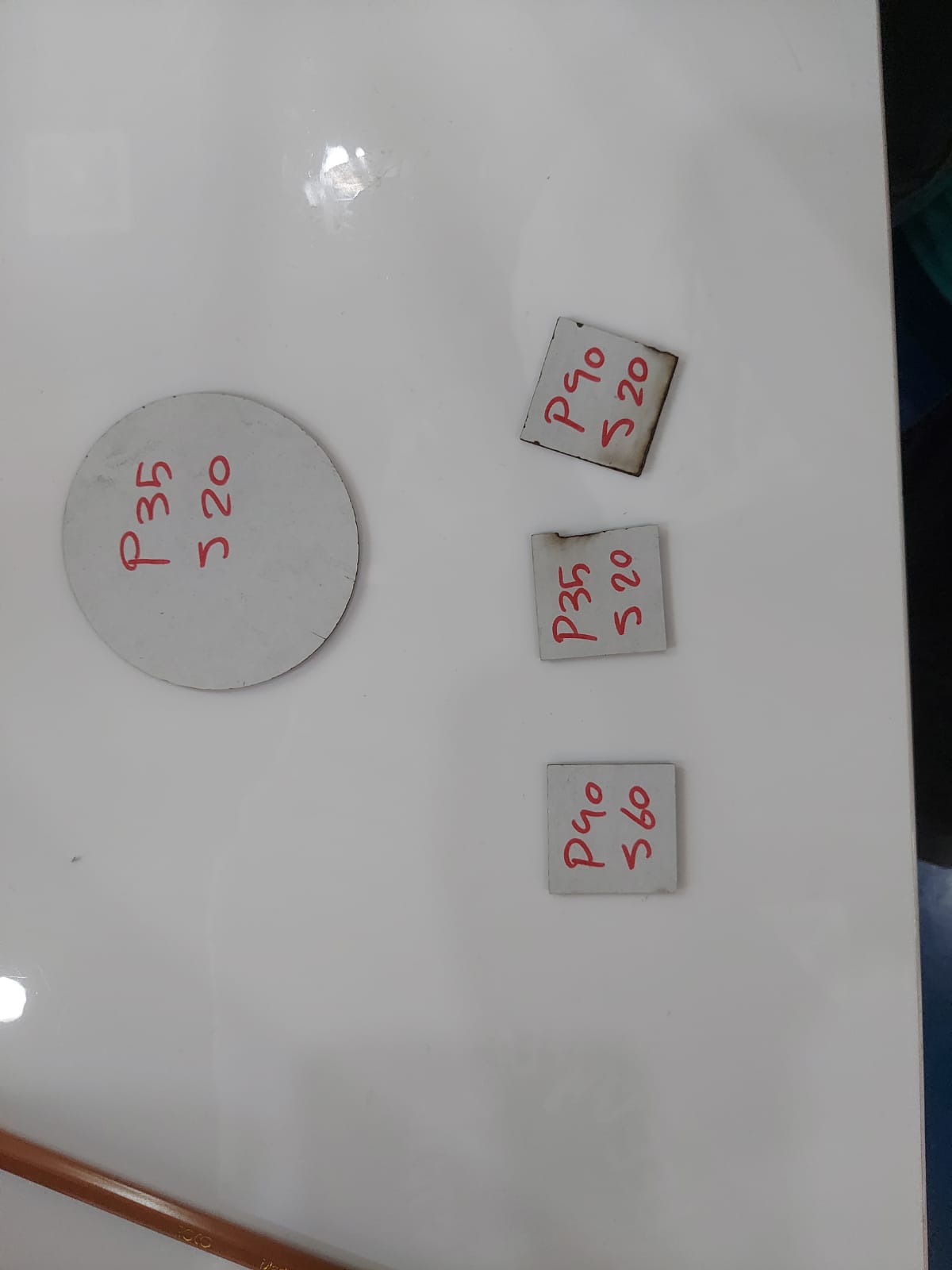
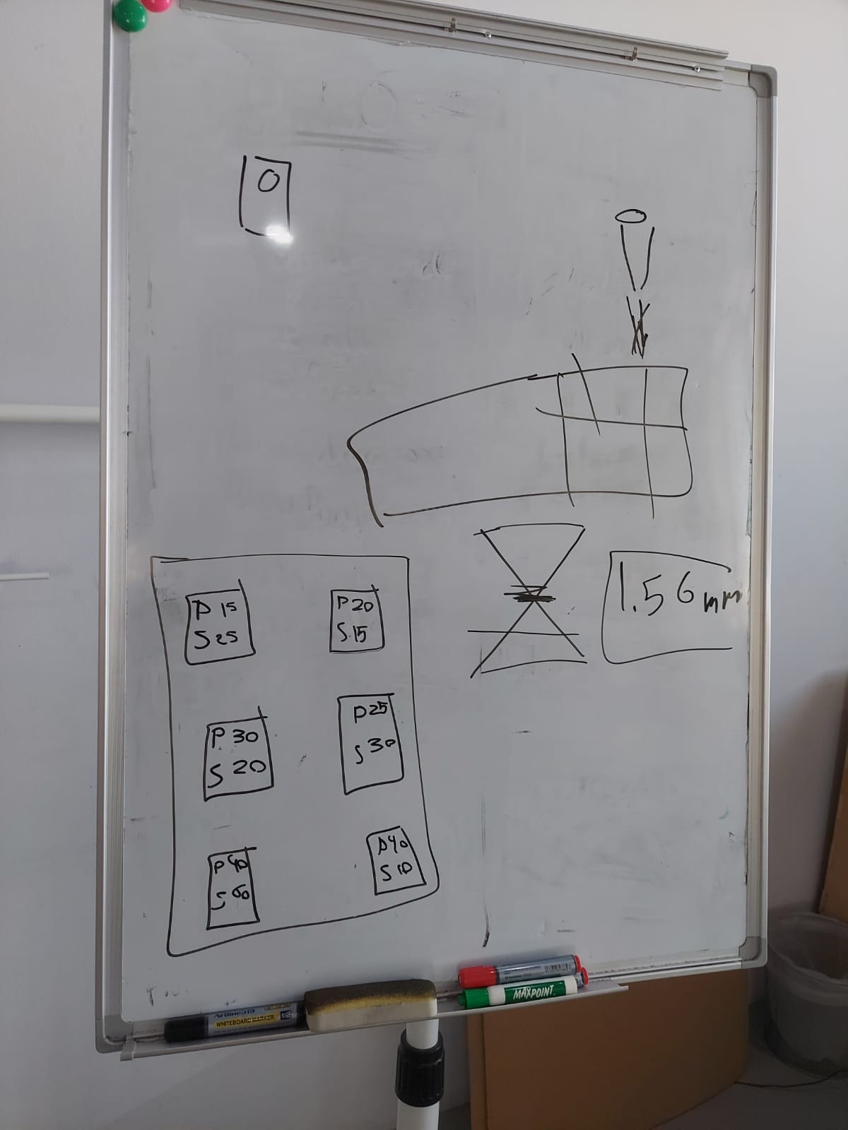
And we found out that this is the perfect setting to cut our project , because we tried different sitting to a different shape :
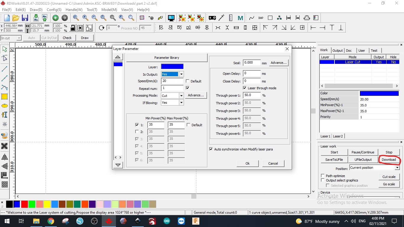
After editing the sittings we clicked to download to send our project to the machine :
Before printing anything , we had to adjust the height between our project and the laser :

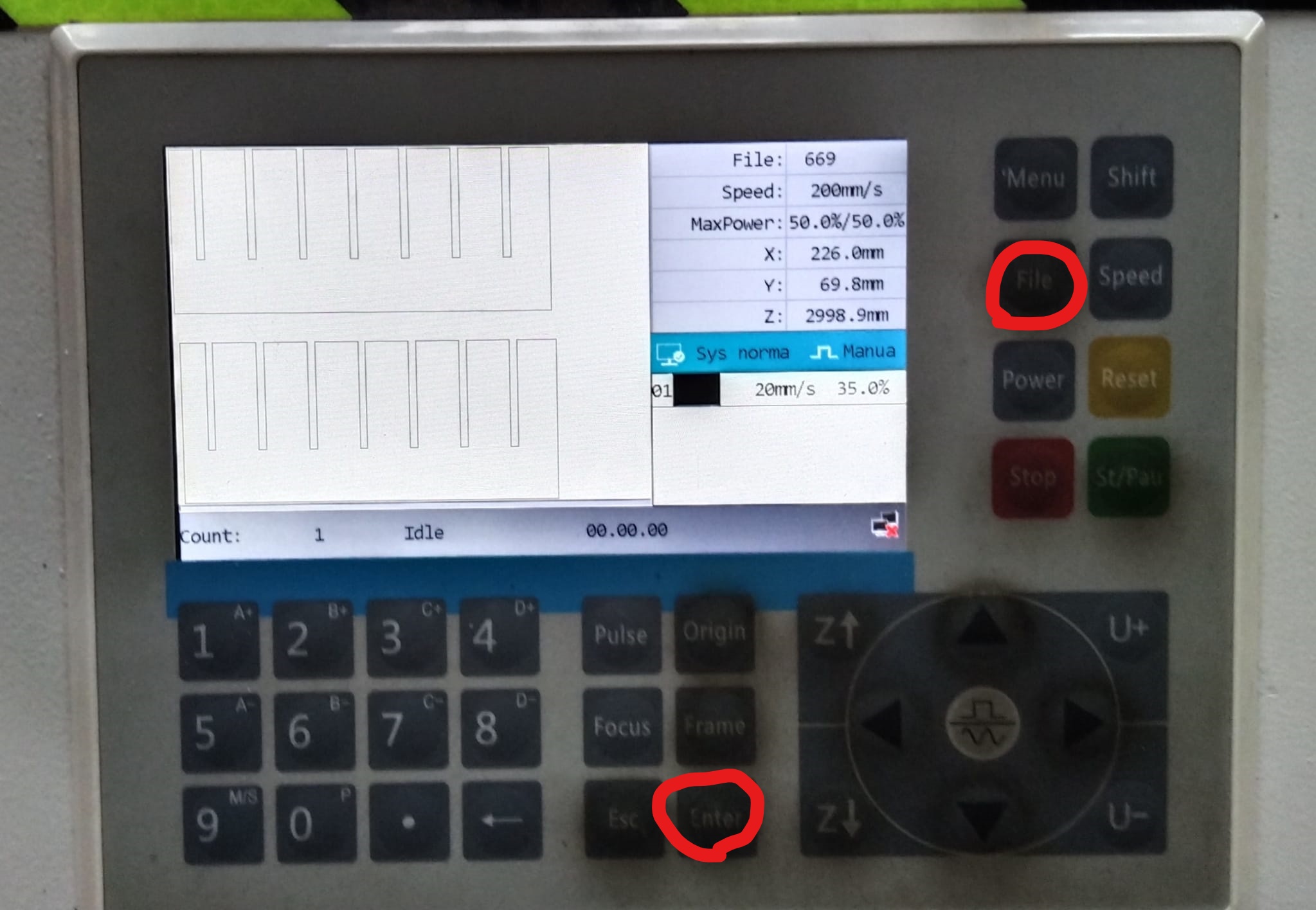
Then we clicked on the file button on the machine to choose our project then we clicked the Enter button :
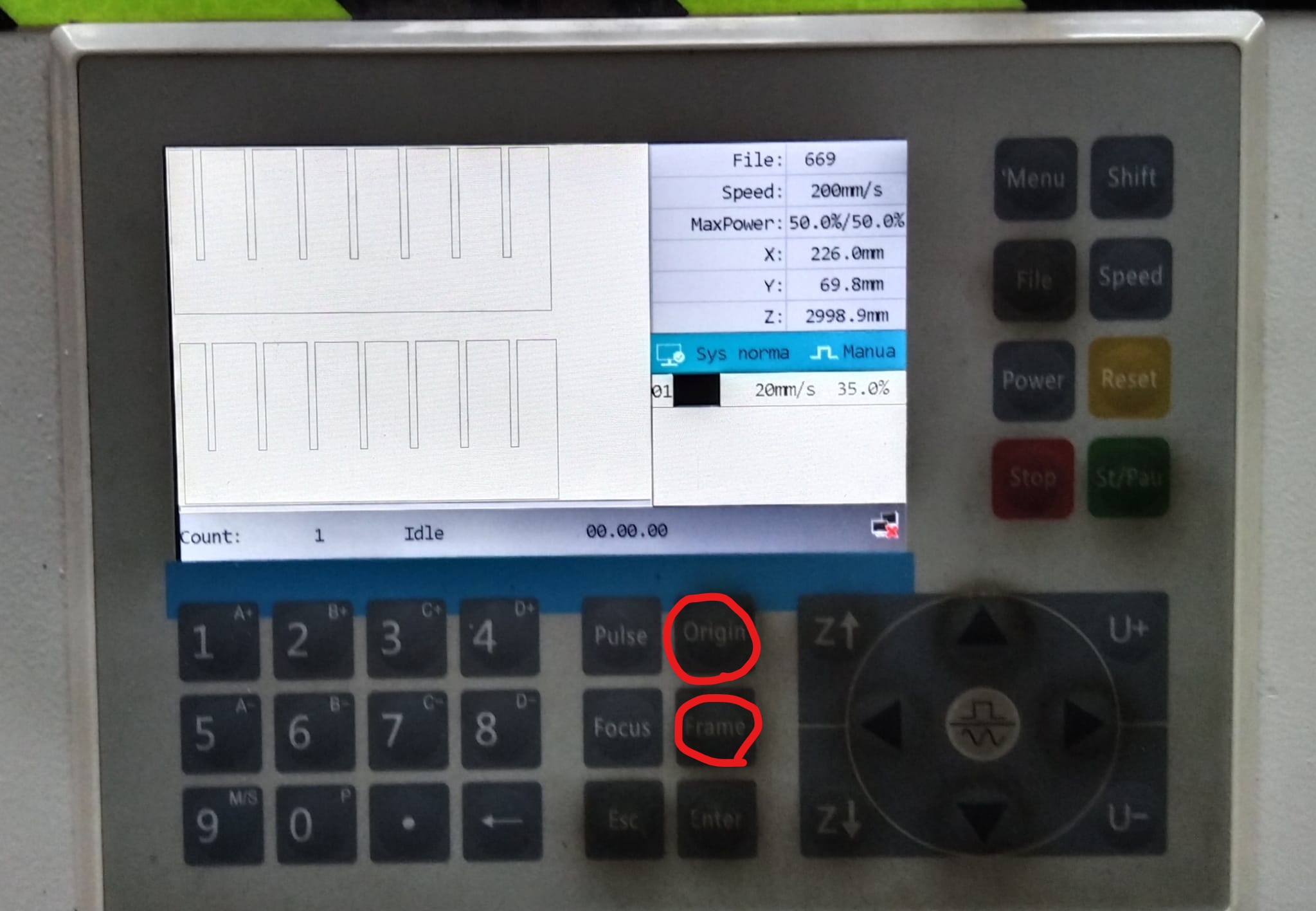
Then we moved the laser to the space that we will print on , and we clicked the origin button , then we clicked on the frame button to see the limits of our project on the sheet :
the video of the framing
We made sure that everything is perfect to start cutting , and we closed the case of the machine , and we clicked start button :

the video of the cutting
The group assignment
The individual project on laser cutting machine :
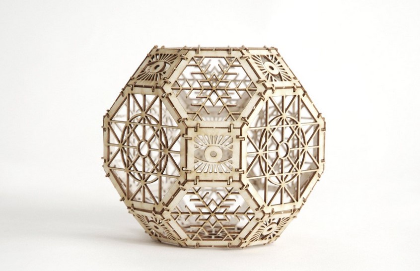
Firstly I chose a shape from internet to apply it :
 The shape link
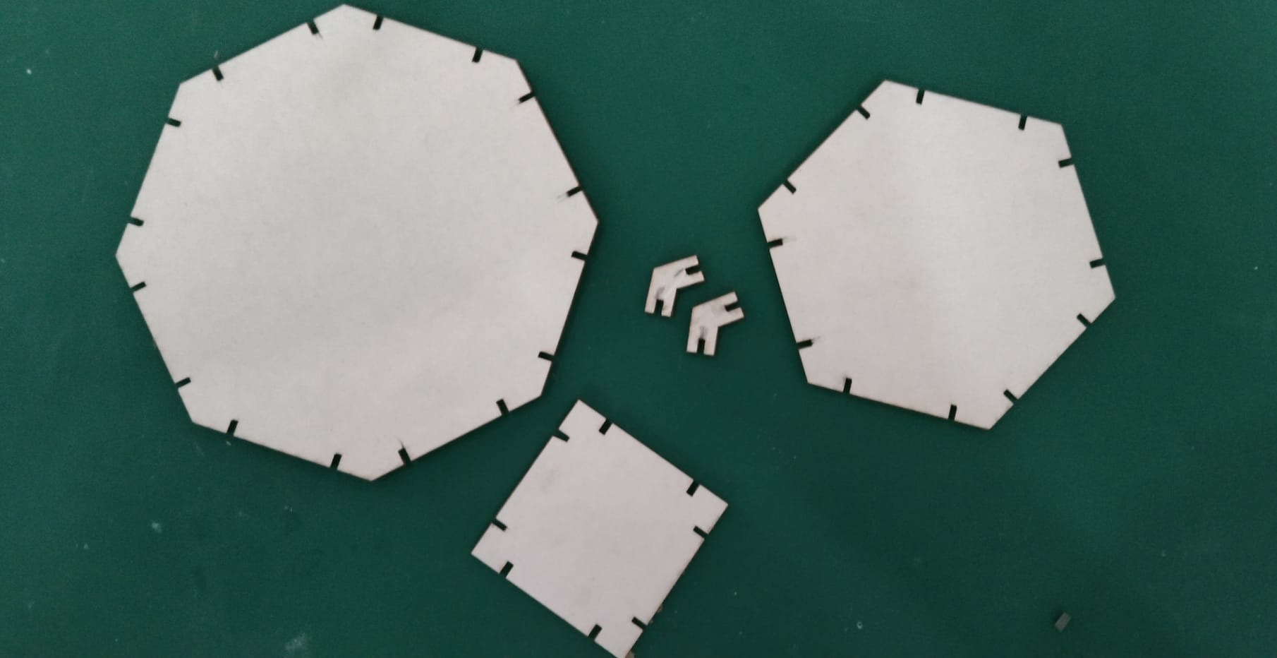
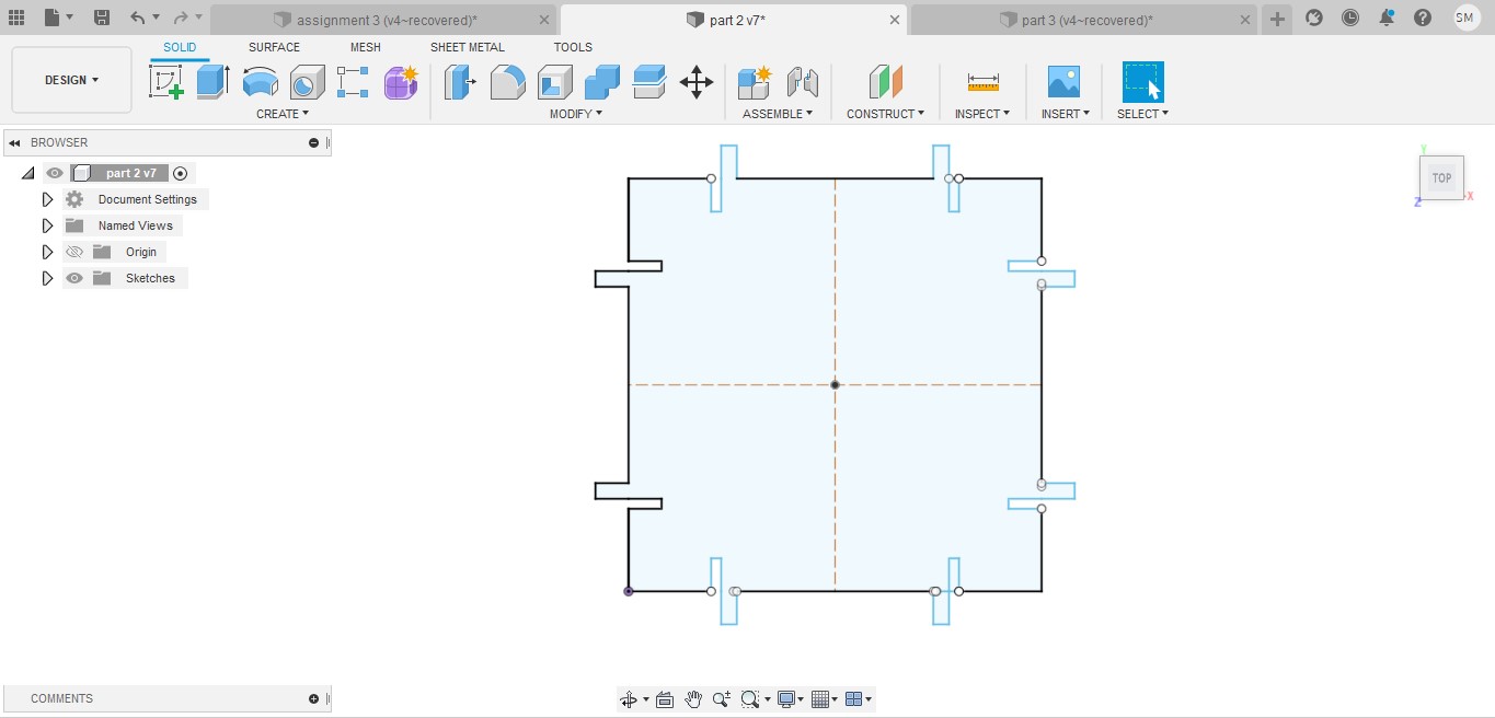
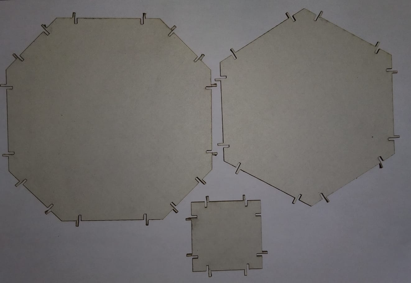
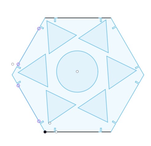
I needed three parts to make shape :
The bigger one :
 The medium one :
 The smallest one :
How to do a parametric design ?
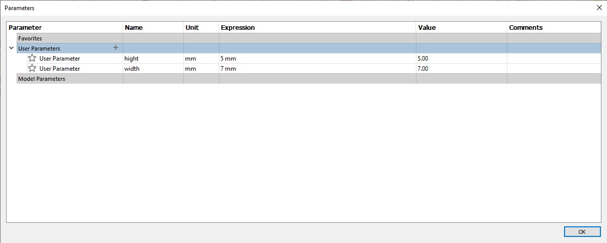
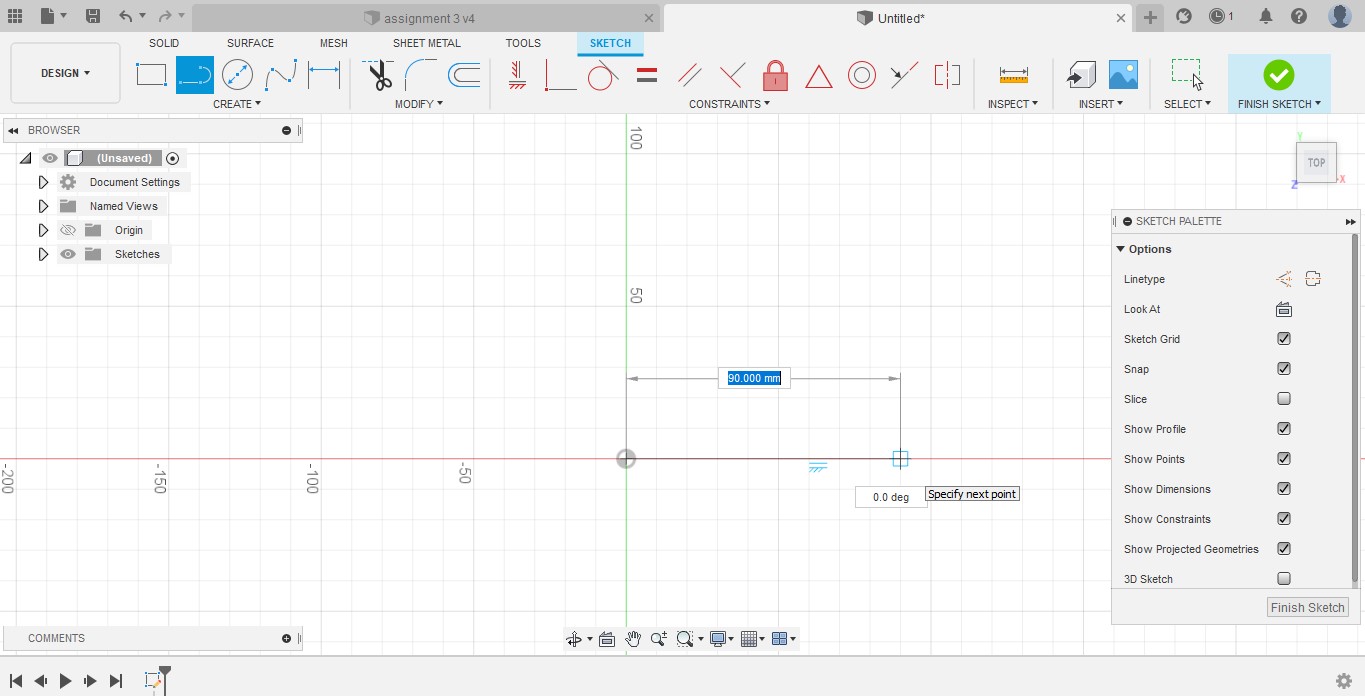
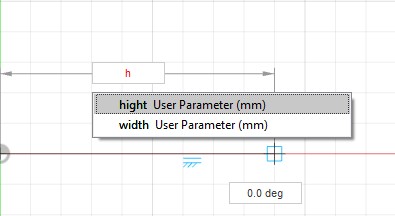
For doing a parametric design you have just to follow these steps :
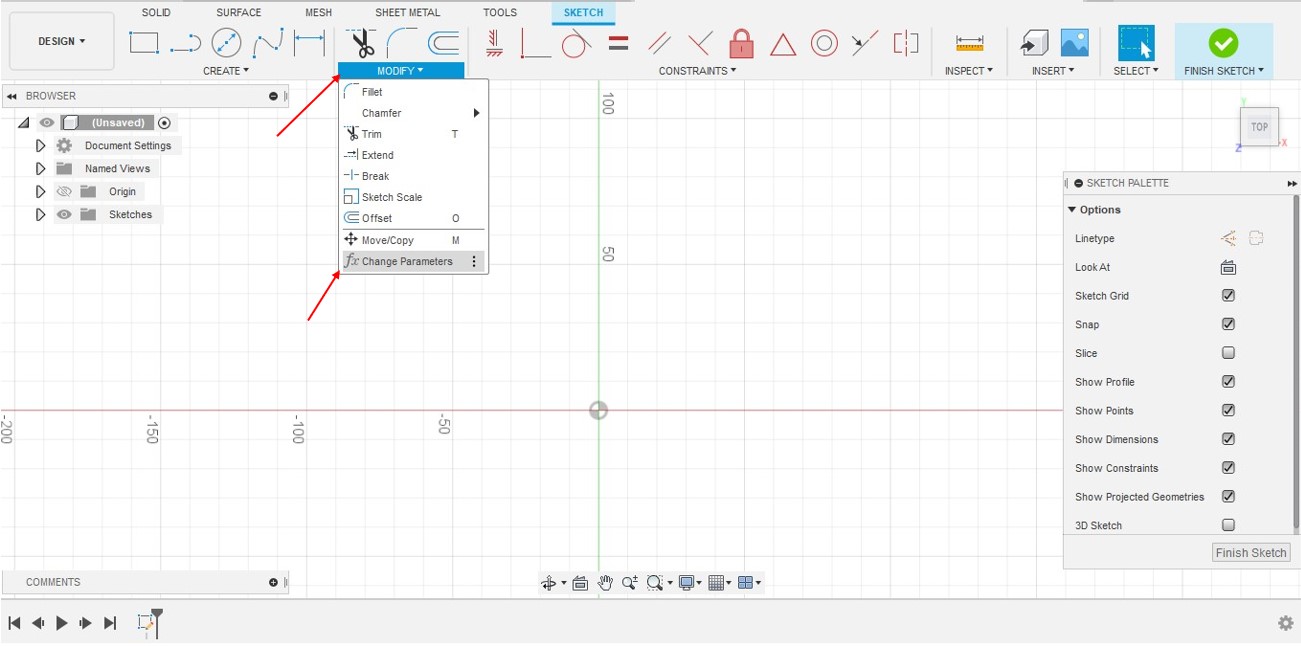
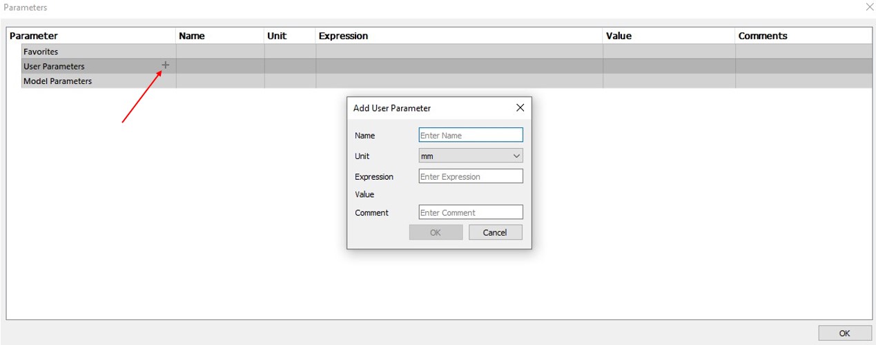
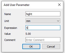
Apply the previous steps dependeing on how many parameters do you want Then you can apply it whenever you want
I applied these steps to whole my designt that i made this week
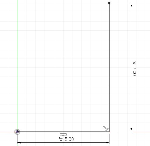
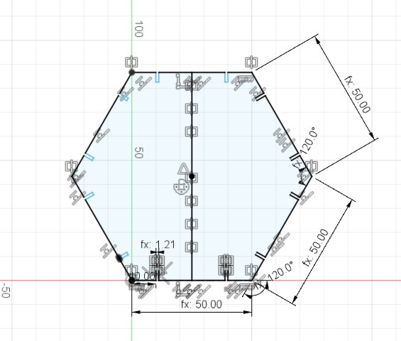
The first problem in the design :
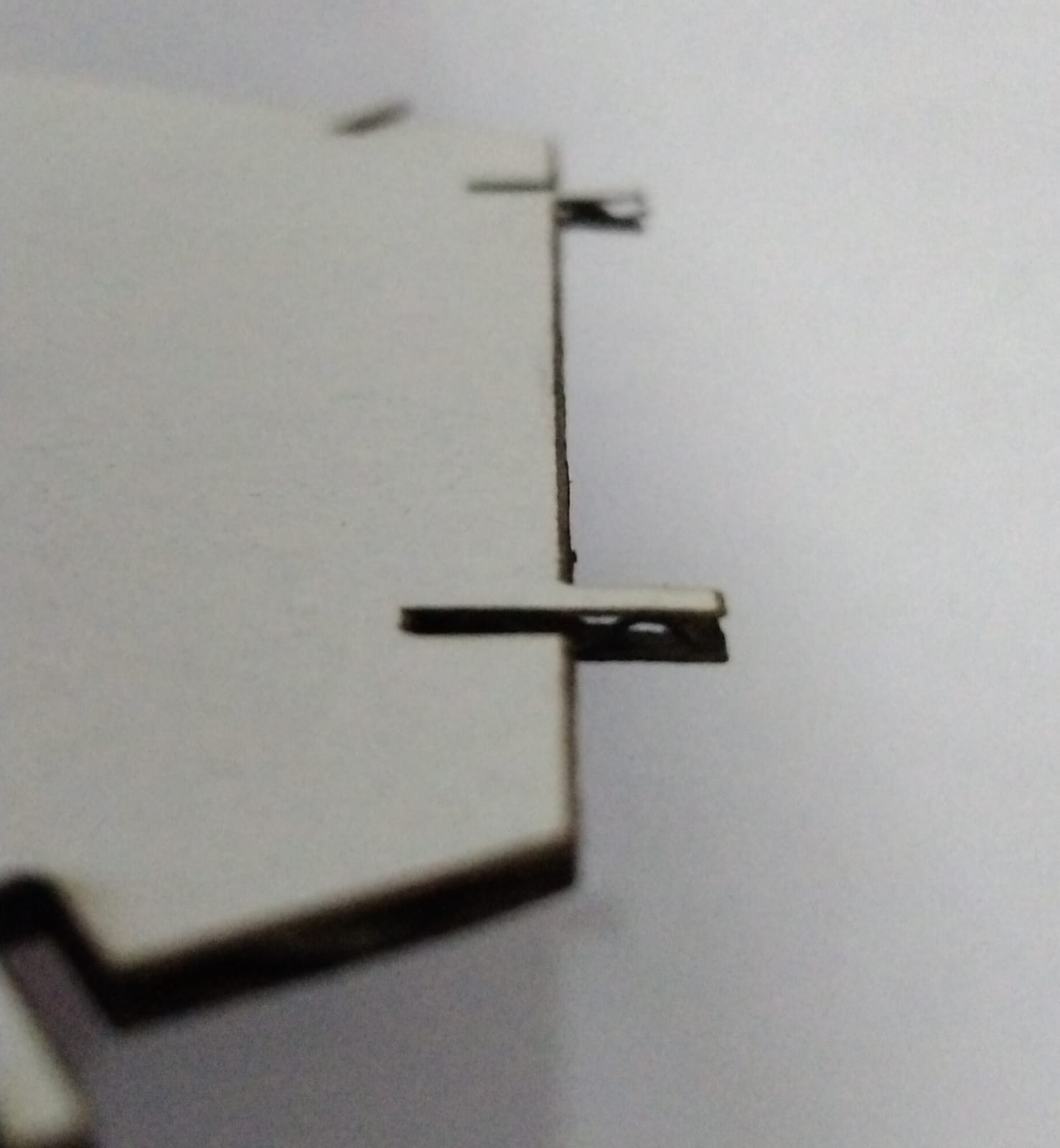
I faced a problem while making the shapes to the project , the problem is the thickness of the joint and the width of the holes :
At the first try , I made both the thickness of the joints and the width of the holes about 1.21mm :
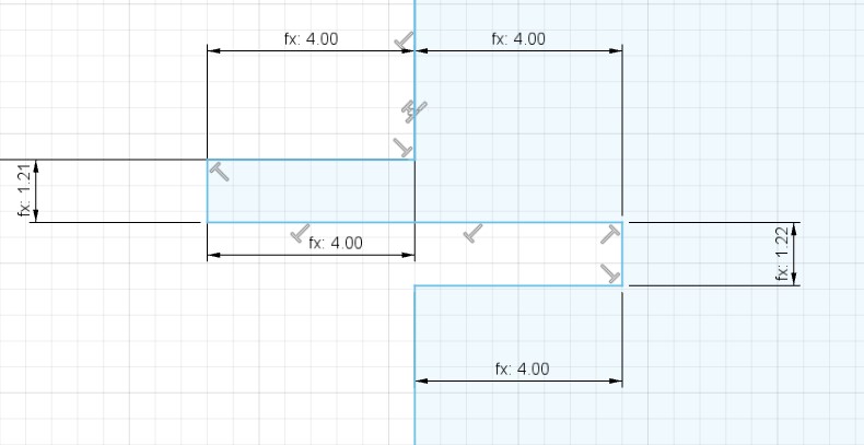 But unfortunately, I did not consider that the laser will take a little bit from the dimensions
and the holes became much bigger than I expected also the joints became more thinner .
But unfortunately, I did not consider that the laser will take a little bit from the dimensions
and the holes became much bigger than I expected also the joints became more thinner .
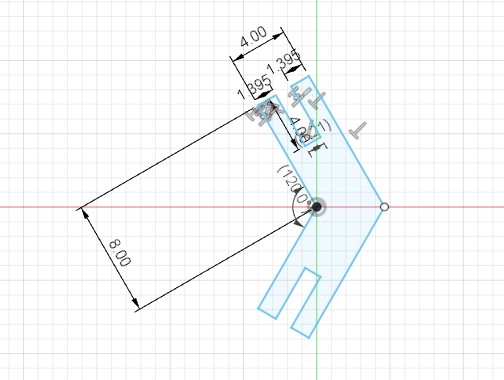
Then I decided to keep the holes width the same but I changed the thickness of the joints
I made three different sizes 1.7 / 1.8 / 1.9 mm :
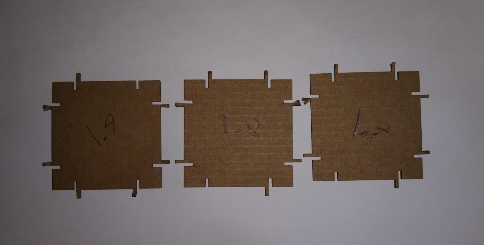
I figured out that 1.9mm is the best size for the holes
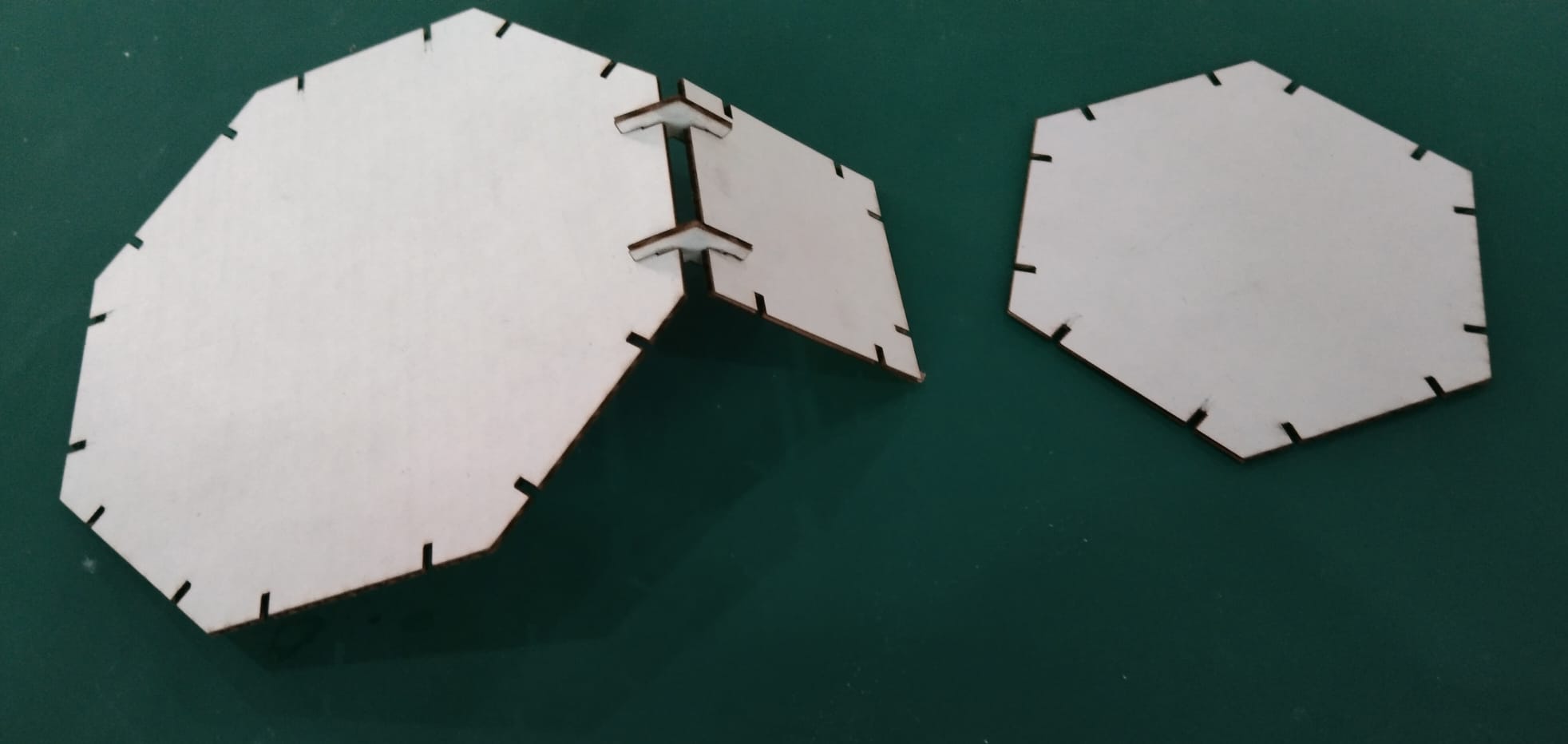
Then I printed the tree parts of the design just to test the joints :
they fitted well but I discovered a second problem
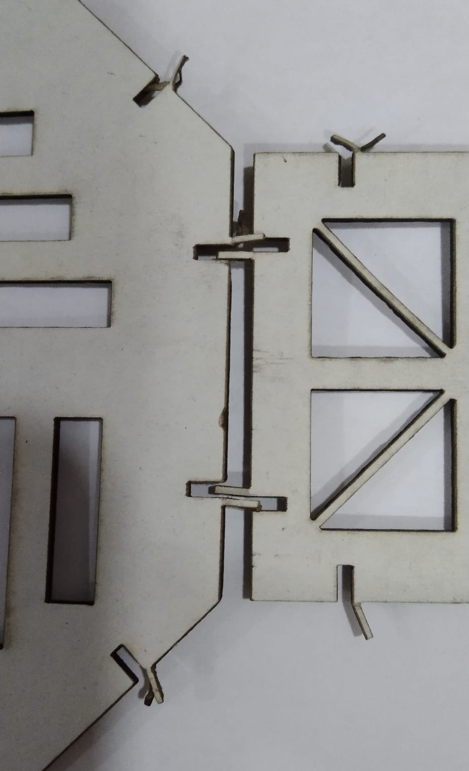
The second problem in the design :
The second problem that I faced is the material that I used , I used cardboard paper . It was so weak to the level that the joints broke while fitting :
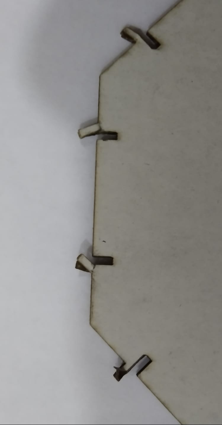
I decided to exclude the joints and to separate them from the shapes
and I made these shapes :

And I made separated joints :
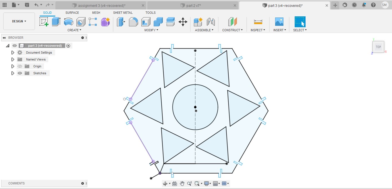
The third problem in the design :
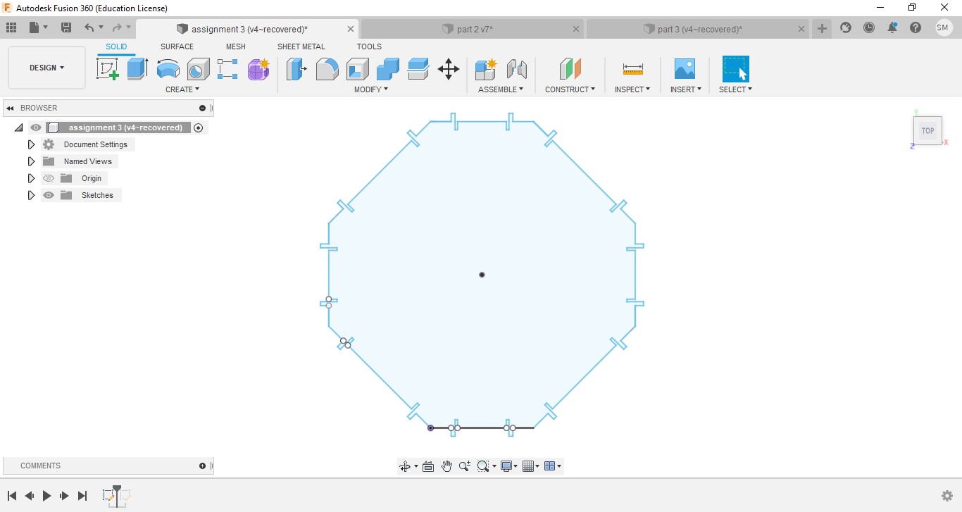
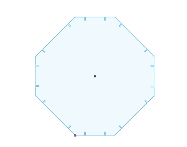
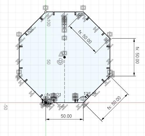
I realized that I made the octagon with different lengths on its sides and I had to fix it by making whole its sides with the same length to allow it to be fit with other shapes.
also the other shapes I made them the same length of the octagon about 50mm .
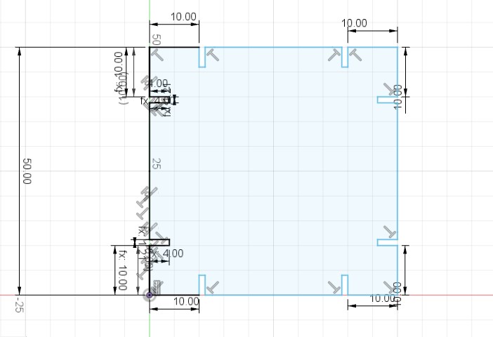
also, the holes of the joint were in different lengths from the angles of the shapes . and I had to fix it by making whole the holes about 10mm from the angle.
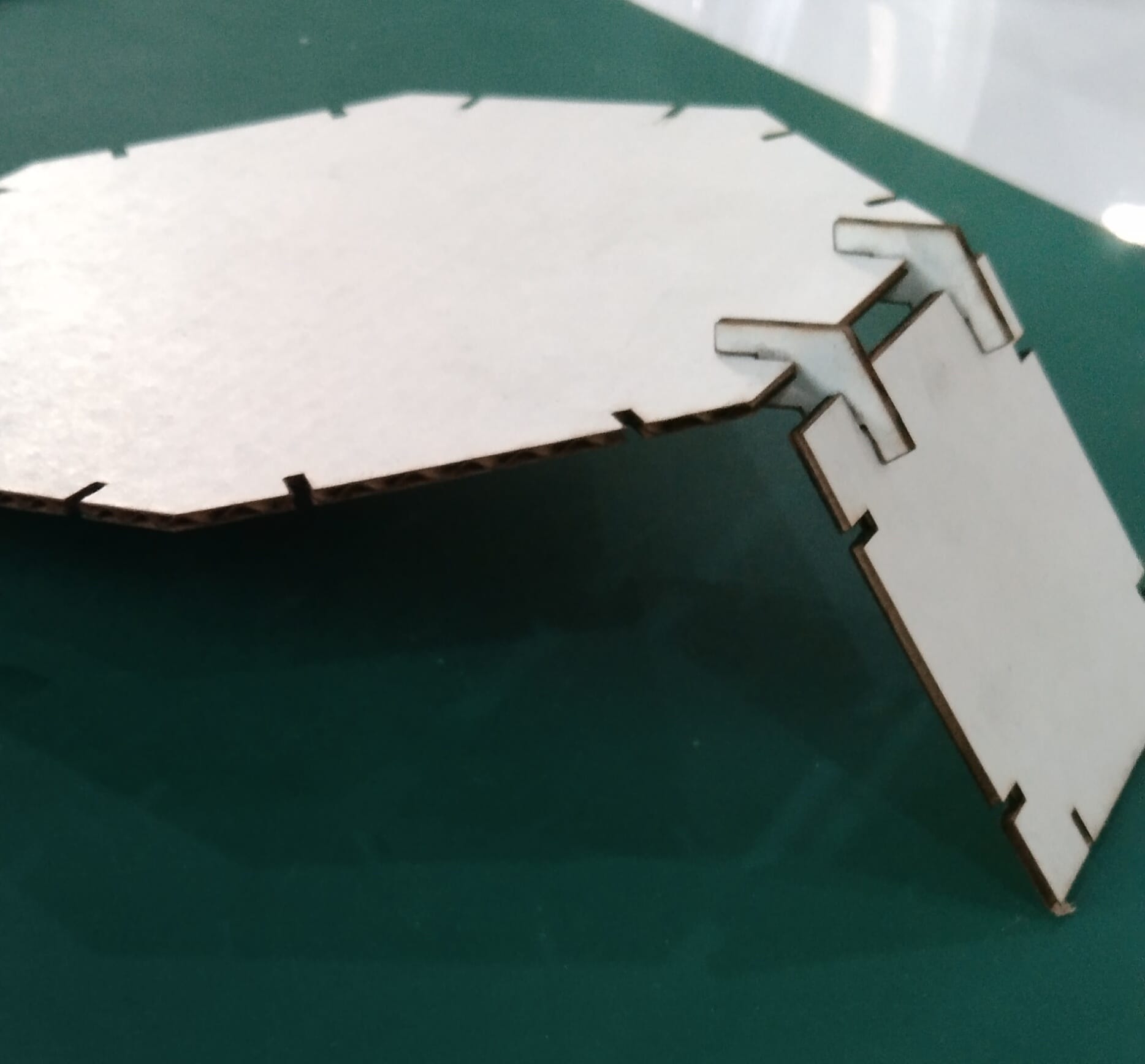
The result :
The result became more practical than the previous idea :