7. Input/Output devices
To understand the basics of the input and out put devices we took a brief introduction of the meaning of both deices types. The device we are using to our assessment is the micro controller “ARDUINO NANO USB MICROCONTROLLER”. On the embedded programming I have explained briefly the meaning behind the micro controller.
Input Devices
Flame sensor
A flame sensor is an important safety element on your gas heating equipment. During the ignition cycle, your gas furnace undergoes a process where either a hot surface ignitor or a spark actually ignites the gas. As the gas is ignited, the flame sensor generates a current of electricity. The electricity is quantified in micro amps. If the furnace’s control board doesn’t read the proper level of micro amps, the furnace will quit giving the system fuel to stop an explosion. The flame sensor didacts any possible flame from the surroundings this flame sensor is electrically connected through a circuit which is attached to the micro controller. The circuit distribution that I have chosen to do is the followed one written in reference (2). The following heading will show you my step regarding the connection diagram of my module.
Specifications
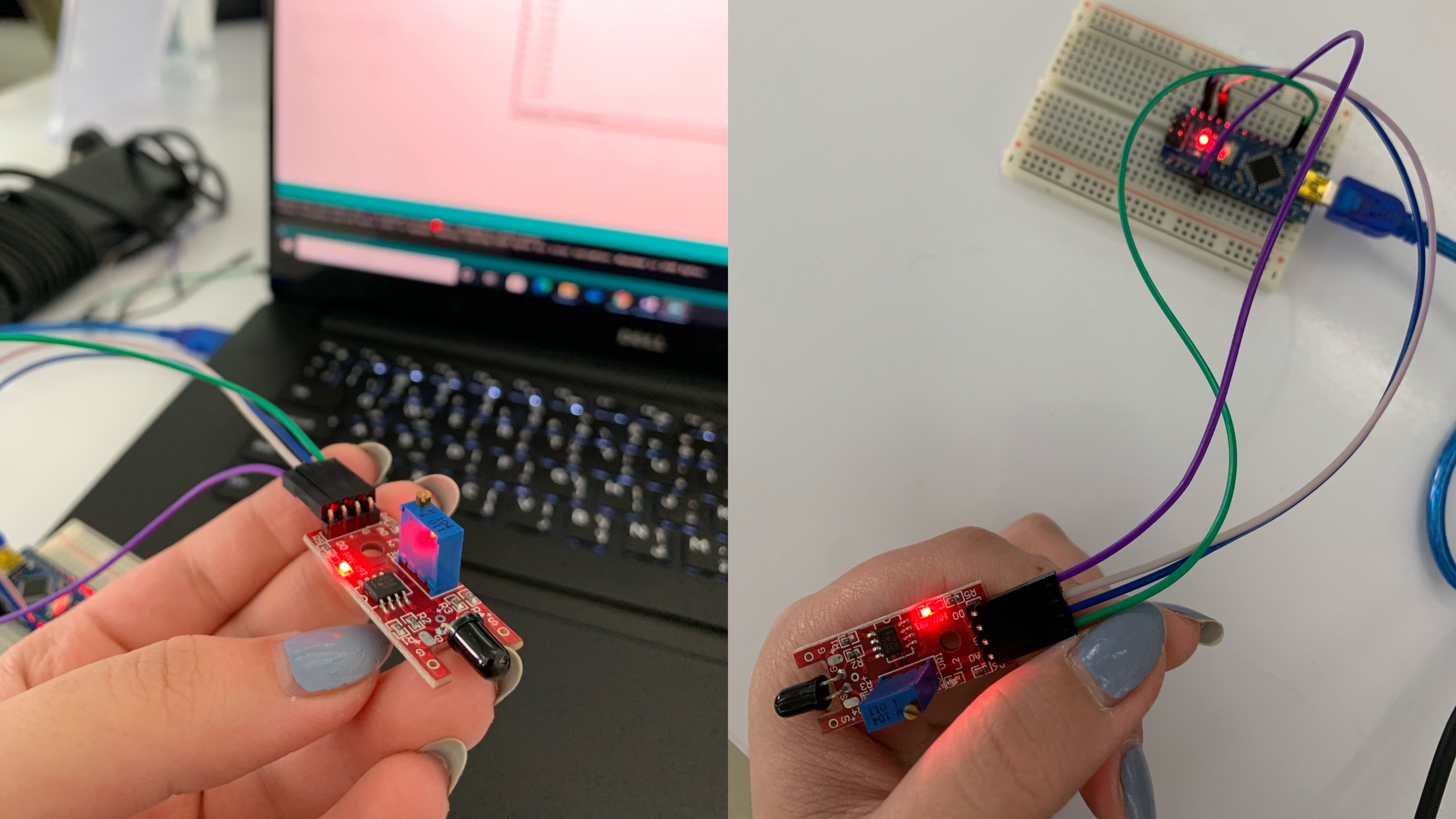
In the following photo you can see the flame sensor specifications and pinouts.
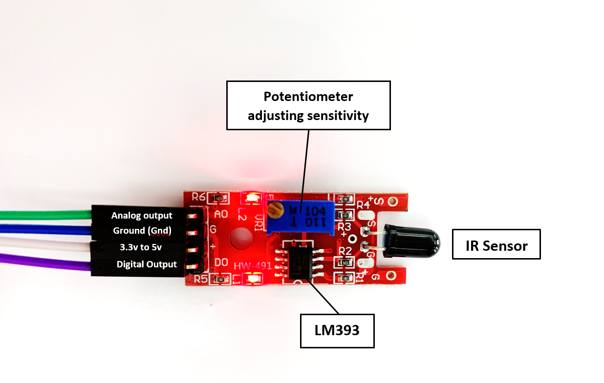
The Flame Sensor Module has a total of 4 male headers on the left side which are clearly labeled as in the following table.
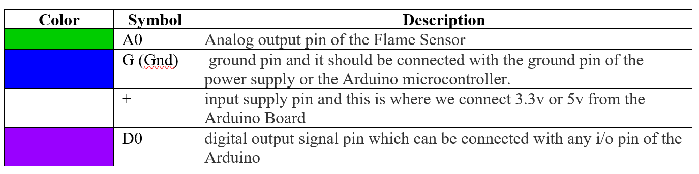 The table above shows each different colors and their representation to ease the understanding of the circuit. The colors are the color of the wiring as showed on the above photo.
Hence, the Potentiometer can be used for adjusting the Fire Flame detection sensitivity. The Flame sensor module is also provided with two LEDs L1 and L2. One LED is turned ON when you power up the Flame Sensor module while the other LED only lights up when it detects the flame. Moreover, On the right you have an IR LED sensor; this IR Flame Sensor module is based on the LM393 low offset voltage dual comparator.
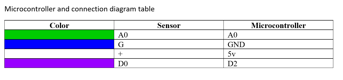
Connection diagram
The following table shows in brief the connection between the wiring of the sensor and the microcontroller.
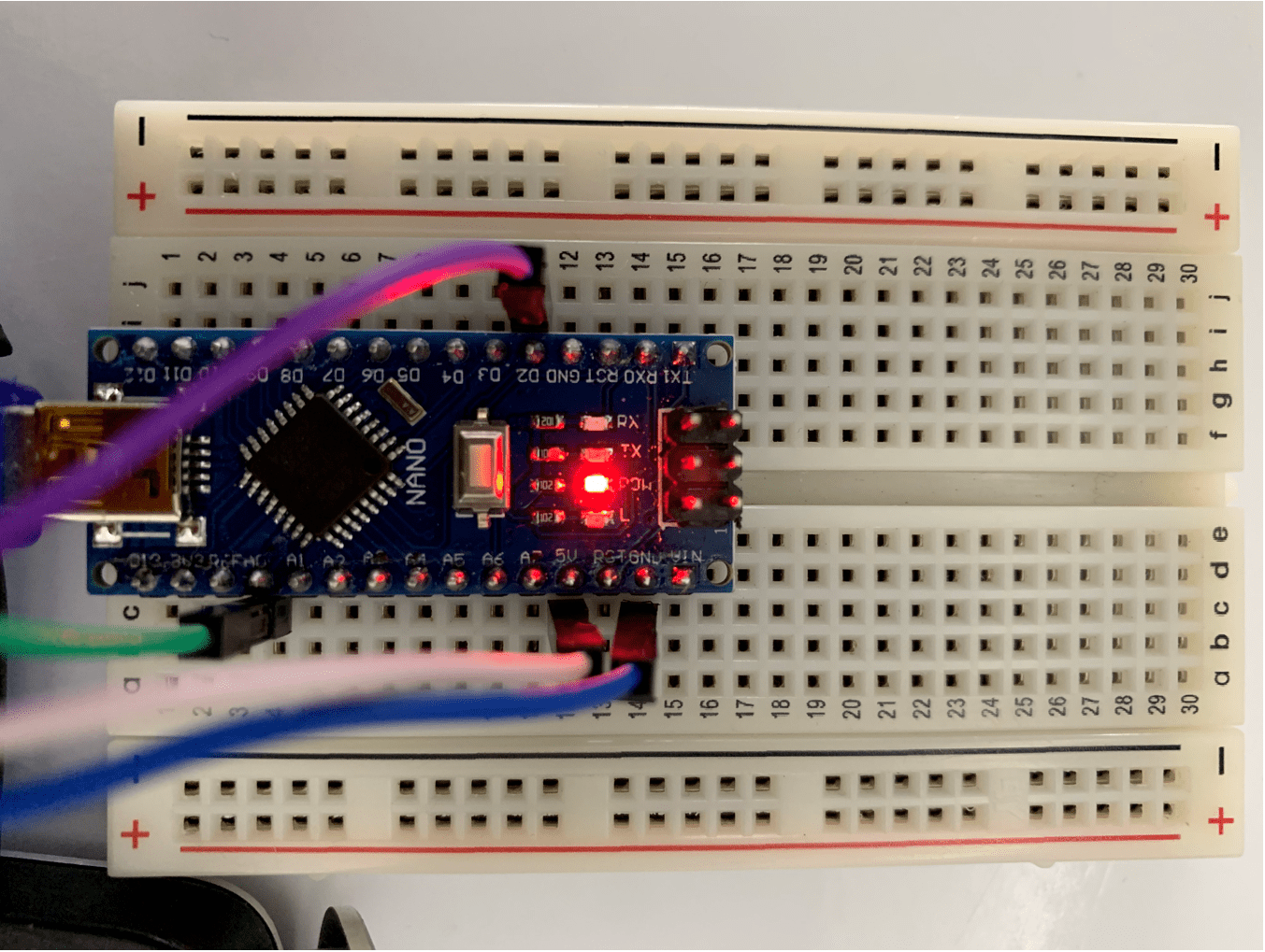
 The photos below show the connection diagram of the flame sensor.
Attempts
In this section I will show all my attempts on doing the flame sensor code
First attempt
My first attempt I have used multiple codes to do work with the flame sensor, but it did not sense the flame I was applying to it. Hence, the code was delaying the results, when I stopped applying the flame the sensor diadectid the flame after a roughly 30 seconds that there was a flame. And the other problem was even if I touch the surface of the laptop or my lap it will change also of having a flame on the sensor. Unfortunately, I did not document my whole work since a sudden stop to my flame thrower that I was using to apply flame to the sensors. One of the problems I have faced that the flame IR dedicator will not didact the flame directly so I have tried many other codes that I will be mentioning on the references headings, in order to know the source of the problem. I have come to that the flame IR was not working. So I have dealt with the sensor while is not working and understand the concept behind the code. By this, I will try using other codes and figure out the problems on next time.
Second attempt
My second attempt was applying another code than the one I used, I thought that my code is not working perfectly with the sensor. But also nothing changed on the results and also did not sense any flame applied to the surrounding system.
Third attempt
I have a working plan to work on firstly, is to try to change the sensitivity of the flame sensor to check if it still works. If not I will try to make a final code following youtube video I saw. the following video is the one I am following.
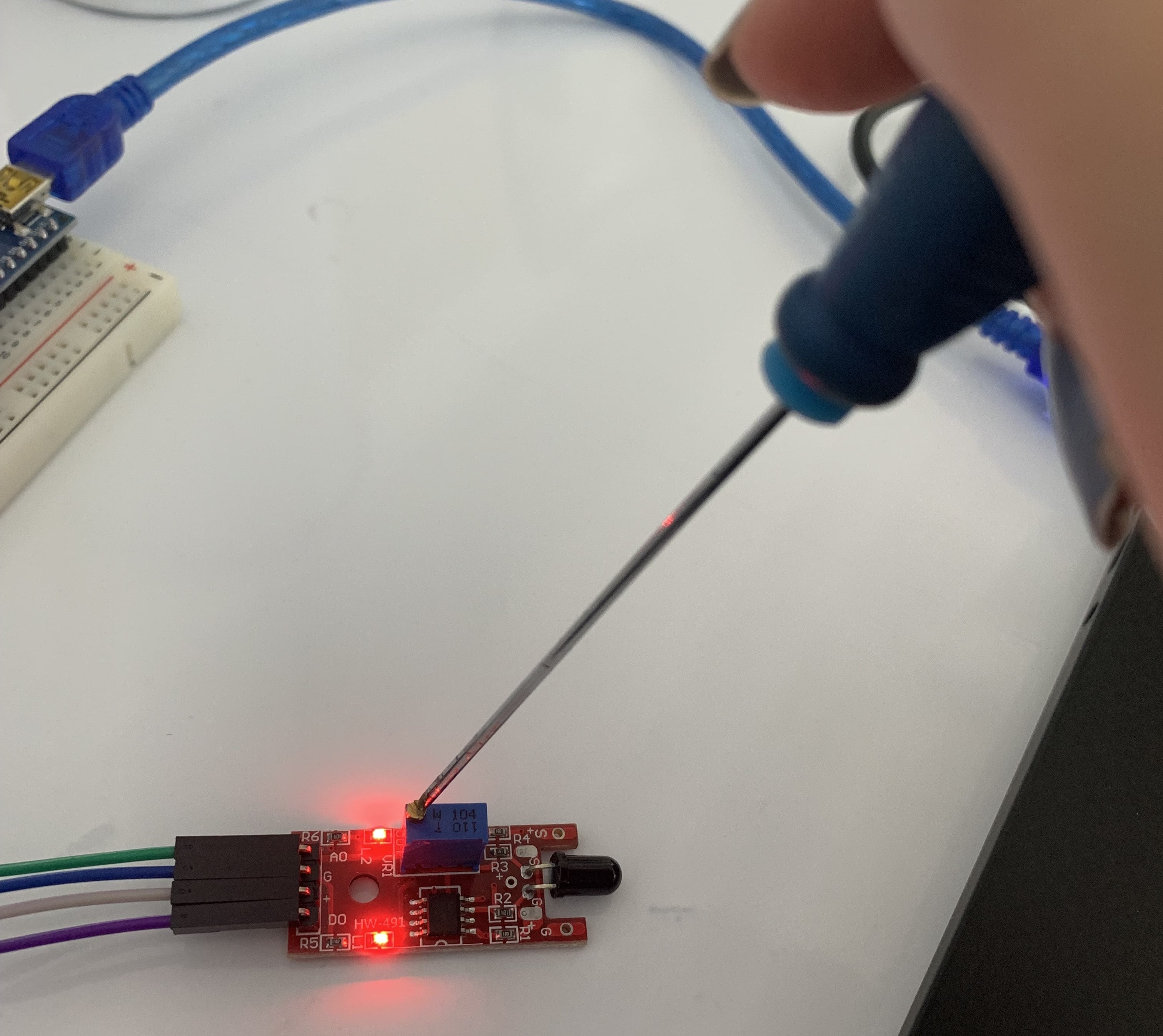
First I changed the sensitivity of the sensor using a screw driver ass followed
 Then test the following code from this source flame sensor code To see if it works.
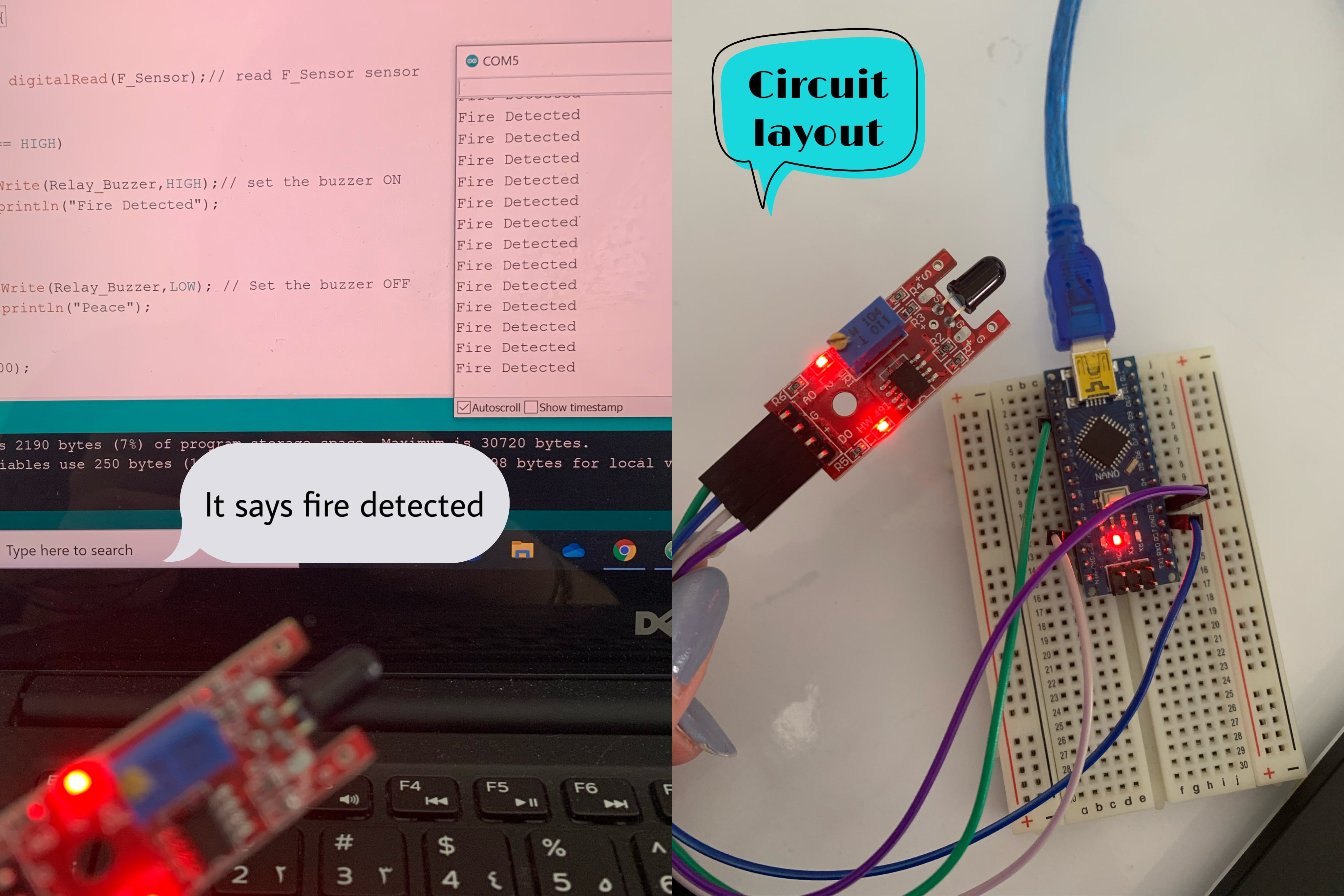
 After changing the sensitivity and try the code the sensor did not detected any flame. The following photo shows the circuit distribution of the sensor and the serial monitor saying that there is flame but I am not applying any.
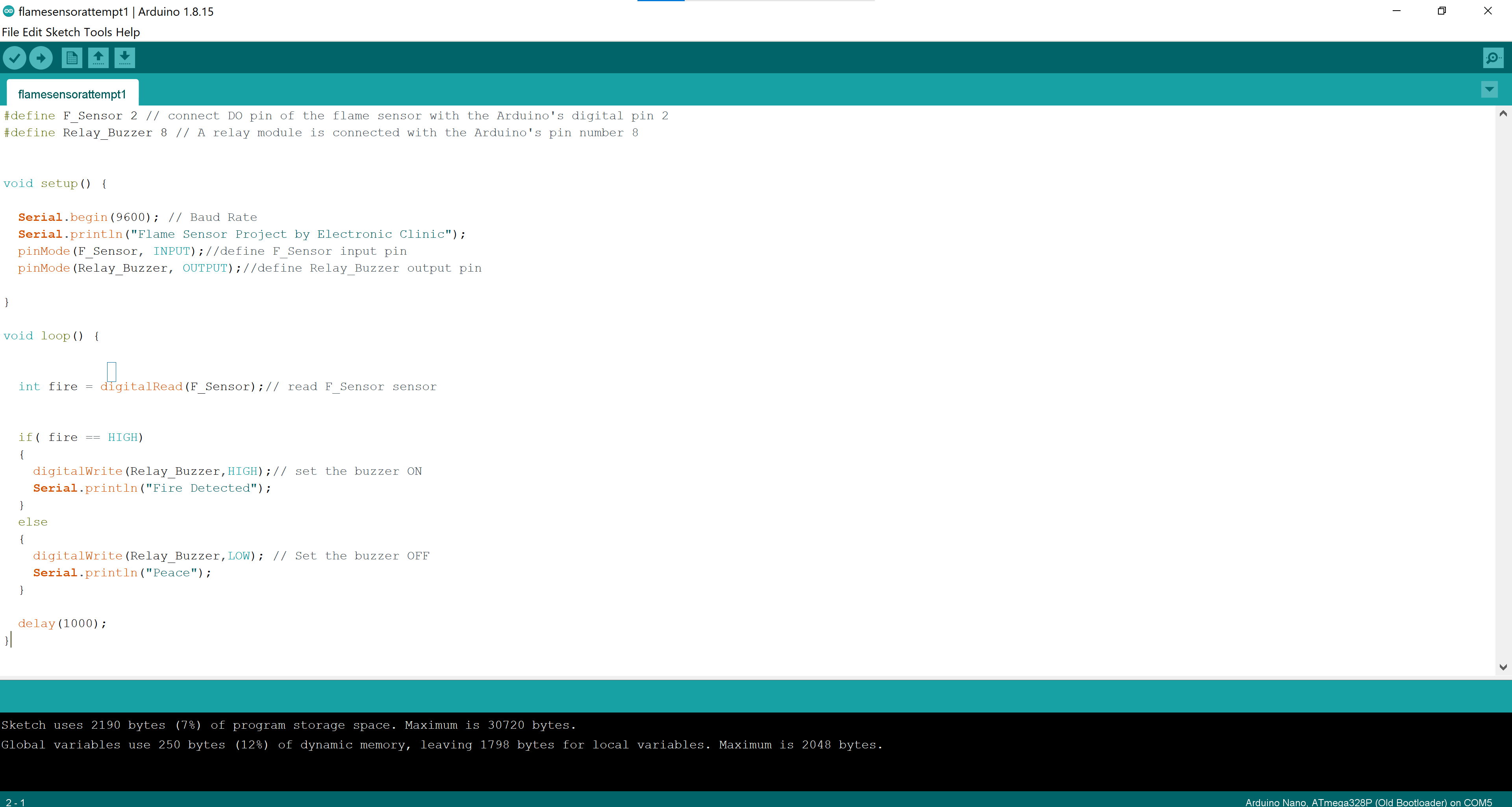
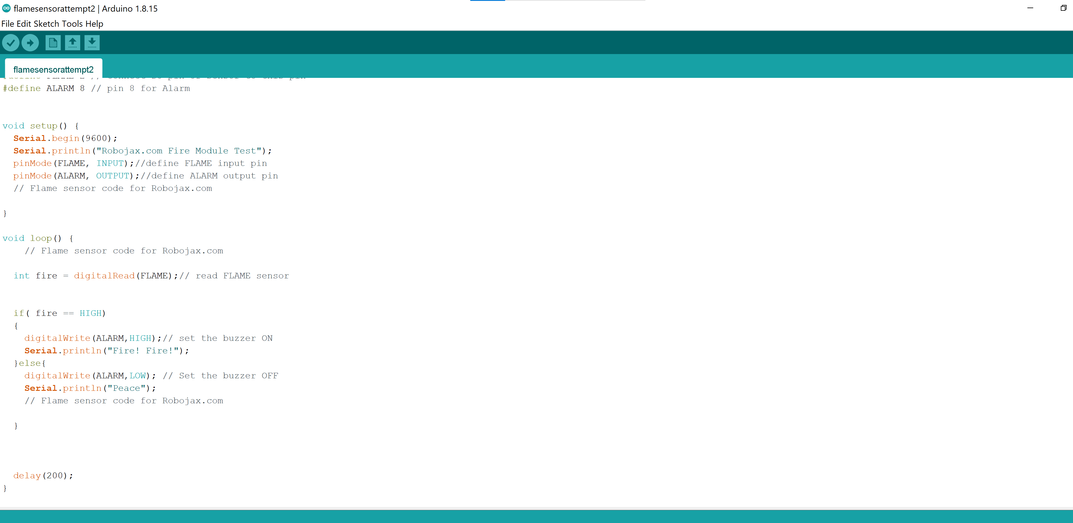
I will try to do the code on the YouTube video. I have tried the code again and figured out hat I may have a problem with the wire connection it self sense I move the board up and down there is a change on the message that appears to the serial monitor that either there is fire or there is not. the video linked shows the problem I have Video. The following picture shows the code I used and the link will take you to the code source. Code source
Forth attempt
My forth attempt is to change the connection wiring to the sensor to see if it works or not. Thus, I still have he issue was not fixed by changing the wires.
JoyStick sensor
The joystick sensor is used for many types of Arduino robot projects but it is most commonly used for video game controllers or any type of controller that involves a joystick.
Specifications
The following photo shows the specifications of the joy stick sensor.
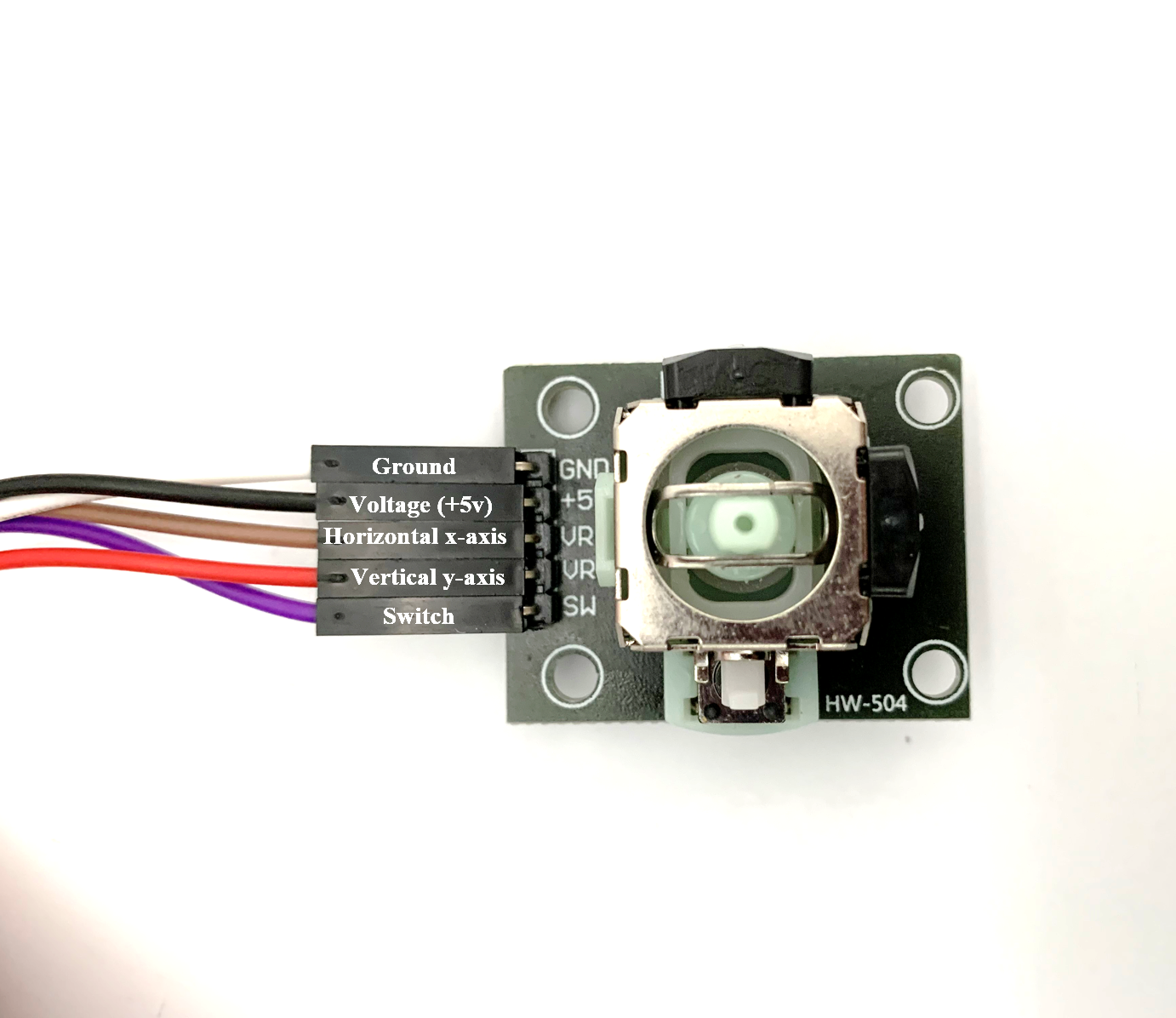 The joystick has a removable plastic cap that helps you move your finger. When removing this cap you have a better view of the pins, the push button and sensors. Analog joysticks are basically potentiometers where they return analog values. The two black covers on the side is the sensor housing. The sensor on the left side is for up and down movement, when moving the stick up and down what is actually happening is that the inner plastic is coming in contact with the side sensor knowing if the stick is being moved up or down this is the y-axis sensor. The sensor on the farthest side of the joystick is sensing movement for left and right which is the x-axis. These sensors is sending an analog read but the joystick also has a push button or a switch, when pushing down on the joystick the switch inside is being pushed down sending a digital read. Since we know how a joystick sensor works let’s connect it to an Arduino and see how it functions.
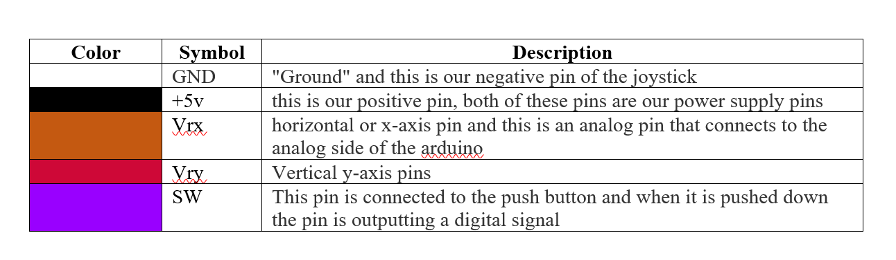
The following table shows the pinout connection and wiring to the joy stick
The joystick has a removable plastic cap that helps you move your finger. When removing this cap you have a better view of the pins, the push button and sensors. Analog joysticks are basically potentiometers where they return analog values. The two black covers on the side is the sensor housing. The sensor on the left side is for up and down movement, when moving the stick up and down what is actually happening is that the inner plastic is coming in contact with the side sensor knowing if the stick is being moved up or down this is the y-axis sensor. The sensor on the farthest side of the joystick is sensing movement for left and right which is the x-axis. These sensors is sending an analog read but the joystick also has a push button or a switch, when pushing down on the joystick the switch inside is being pushed down sending a digital read. Since we know how a joystick sensor works let’s connect it to an Arduino and see how it functions.
The following table shows the pinout connection and wiring to the joy stick
Connection diagram
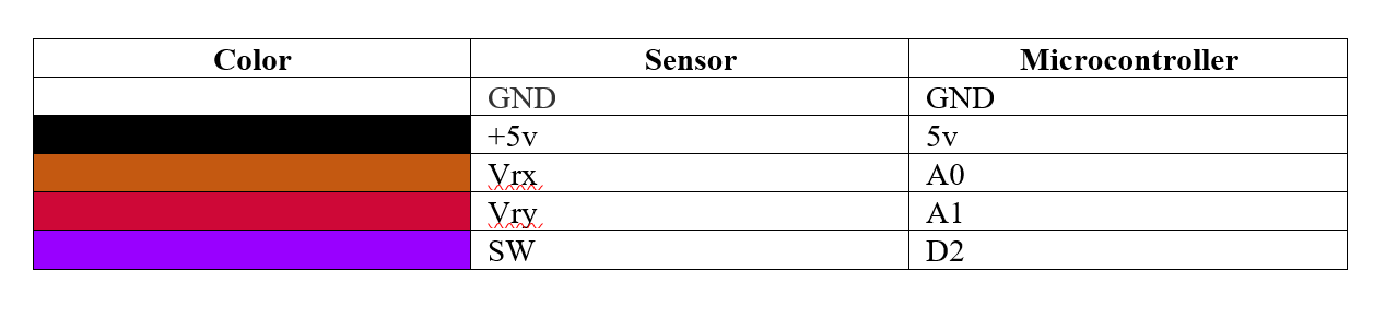
Hence, the following table shows the connection circuit of the joystick sensor to the microcontroller which is placed on the bread board.
Final application
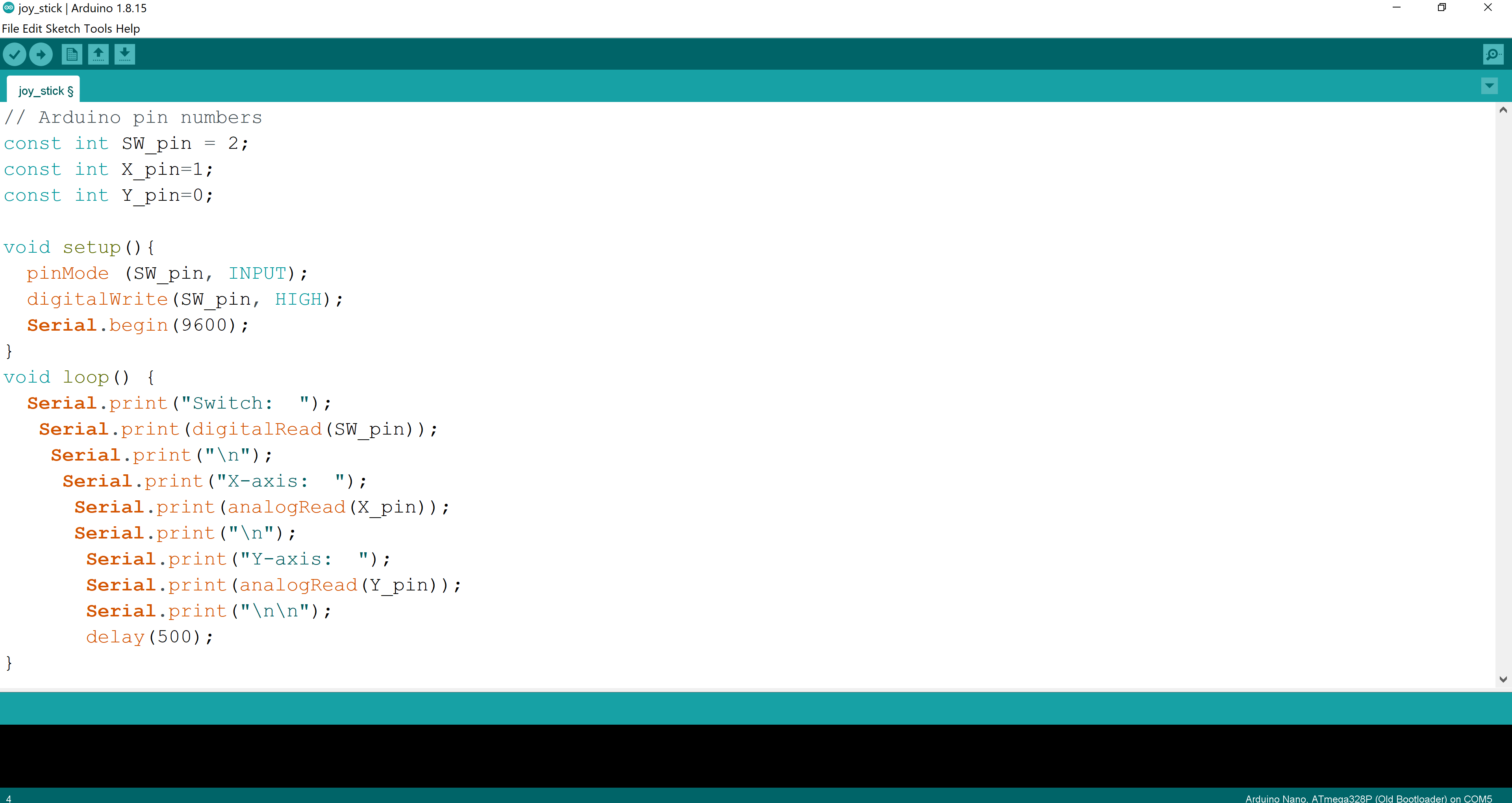
The linked video shows you how it operates. The start of the video shows that I am pressing the switch key and the serial monitor show that is 0 when I am pressing it and 1 when I stop. When I move the tip to up in the video it changes the x-axis points, you can notice the value is changing same as the y-axis that has the left and right movement of the stick.
Applied changes
I have tried to switch the wiring to switch the x and y axis of the device. The screen showed the change on the x and y planes. By switching the code to the following code I have changed the x and y of the joy stick. By changing it on the code I have changed it also on the bread board. The following code shows the code I have changed in order to switch the axis.
Problems
The only problem I faced is being confused by the x and y planes of the joystick but by seeing the results of both codes I knew the actual axis of the joystick.
Output Devices
Buzzer
Piezo buzzers are simple devices that can generate basic beeps and tones. They work by using a piezo crystal, a special material that changes shape when voltage is applied to it. If the crystal pushes against a diaphragm, like a tiny speaker cone, it can generate a pressure wave which the human ear picks up as sound.
Work
Melody
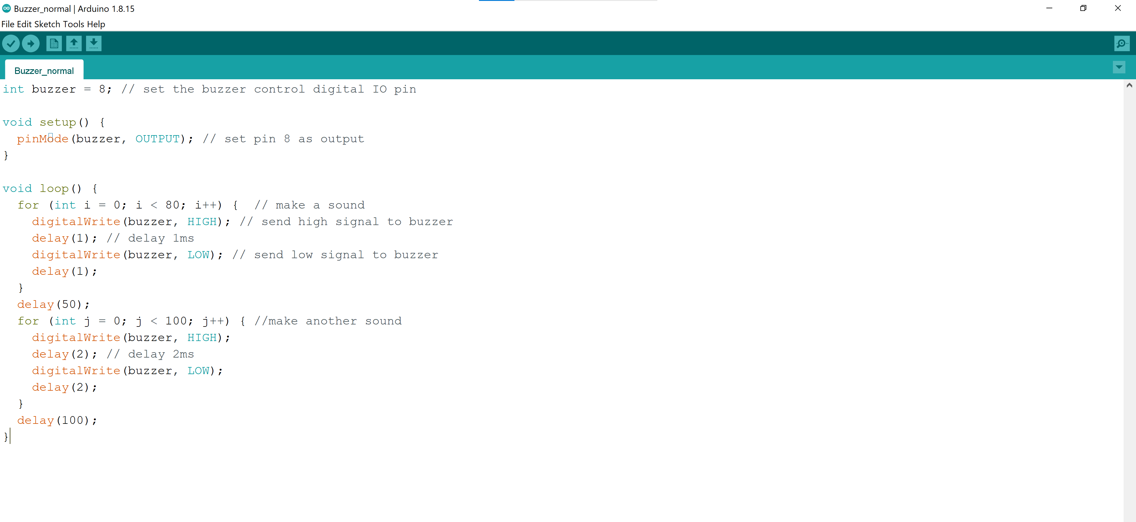
What I have followed to operate my buzzer is doing the following circuit diagram module. Click me!. I have performed a melody to my buzzer by the following code
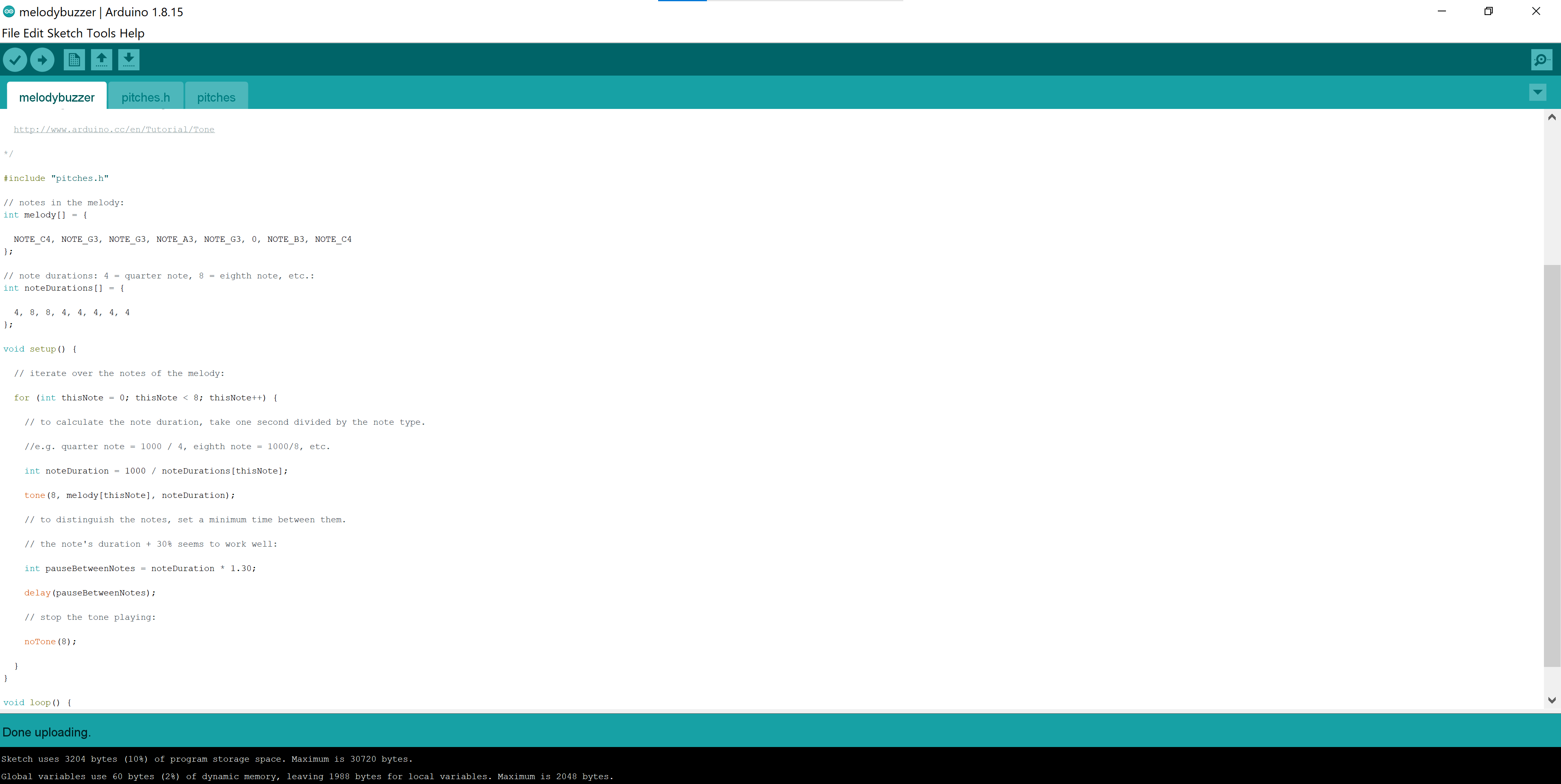 As followed I had to do a new tab inside the sketch in order to have another code file which is connected to the main sketch that has the following code. note: the photo does not show the whole code, but just a part of it. If you want to view the whole code it is provided in the link above.
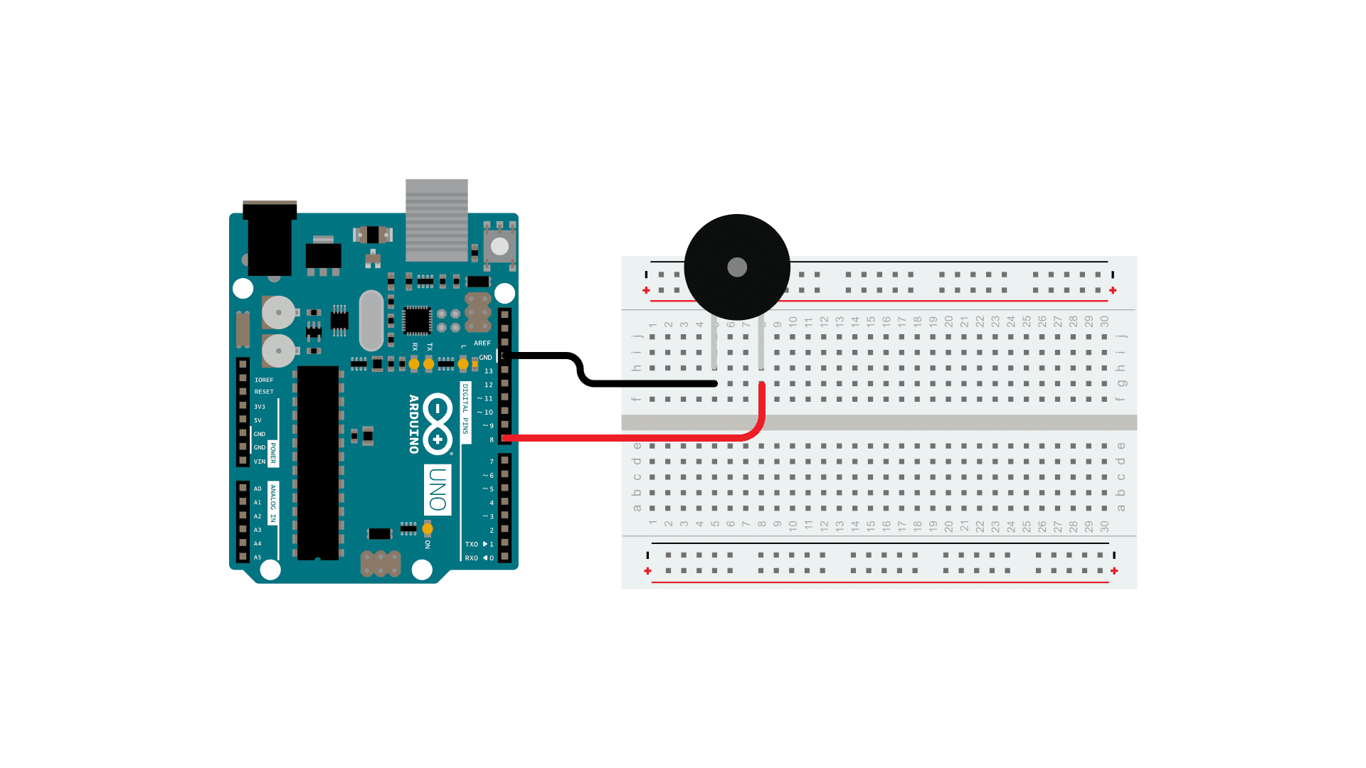
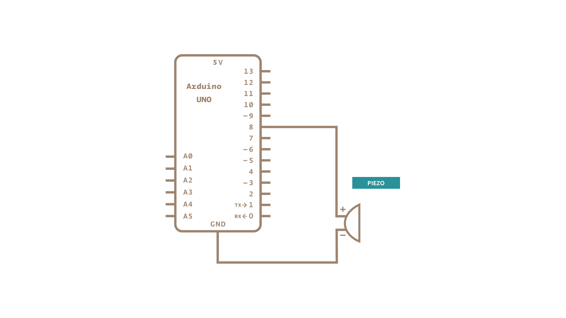
The following photos show the connection diagram that I have used.
As followed I had to do a new tab inside the sketch in order to have another code file which is connected to the main sketch that has the following code. note: the photo does not show the whole code, but just a part of it. If you want to view the whole code it is provided in the link above.
The following photos show the connection diagram that I have used.
 The following video is the video representation of my work to the buzzer. Melody
Normal buzzing
I have used a normal code to do a buzzing sound that sounds like an alarm. The following photo shows the code.
 . The following link is the source of the code source. The video of it operating is linked here
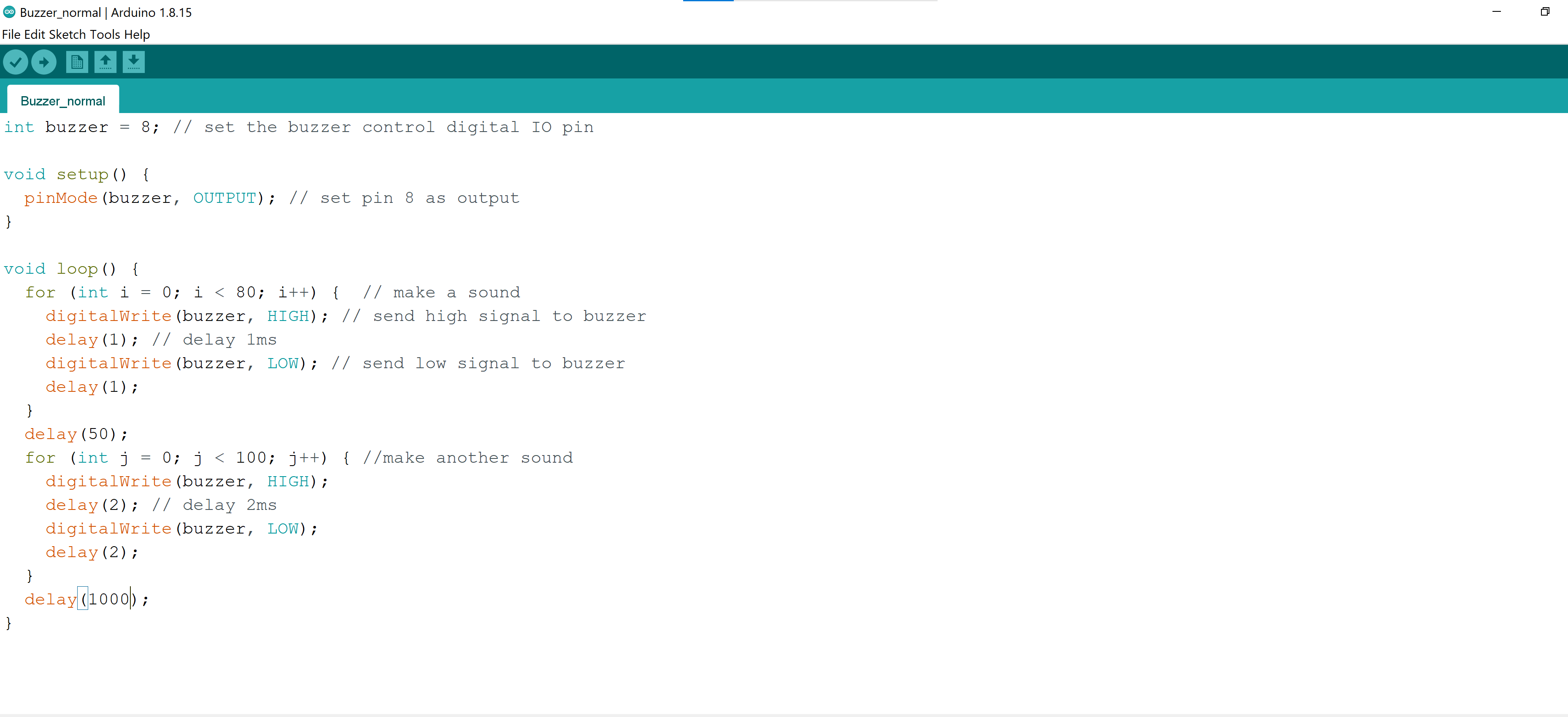
I made some change on the code to have a delay for the sound of frequency of 1000 rather than 100. The code is changed as followed
 . And here you can see the video of the buzzer with the delay sound.
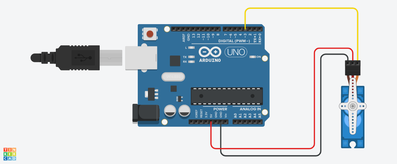
Servo Motor
A Servo Motor is a small device that has an output shaft. This shaft can be positioned to specific angular positions by sending the servo a coded signal. The photo shows how to connect the servo motor.
Work
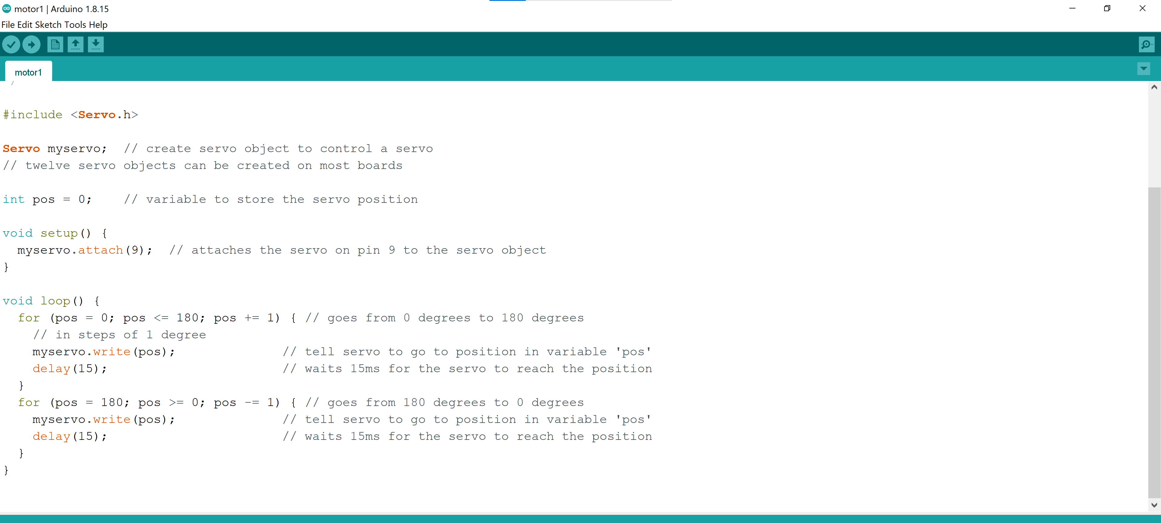
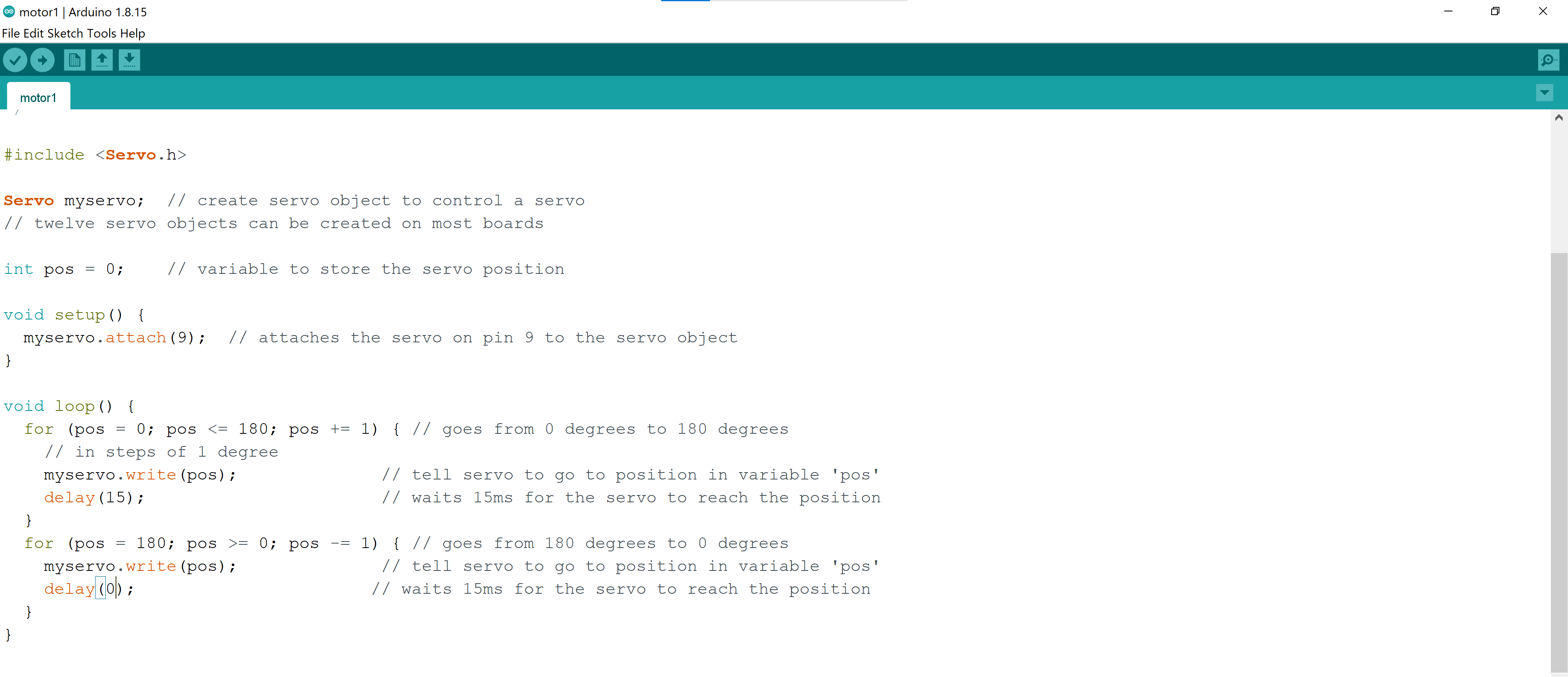
The following code shows how the basic servo motor operates
 here you can see how the motor operated applying the code
The following code is the same as the above but without the delay on the motor so I have put delay(0).
 here you can see how the motor operated applying the code.
Linking the INPUT to QUTPUT
In order to link the input device to the output device. which in my case the input device was the flame sensor and the output device is the buzzer. I have followed this “Flame Sensor and Buzzer Circuit”.
Attempts
First attempt
my first attempts was not working since I have an unknown problem occurring my flame sensor; which I am still stuck with.
Second attempt
I will be using a different input device since my flame sensor is not working.
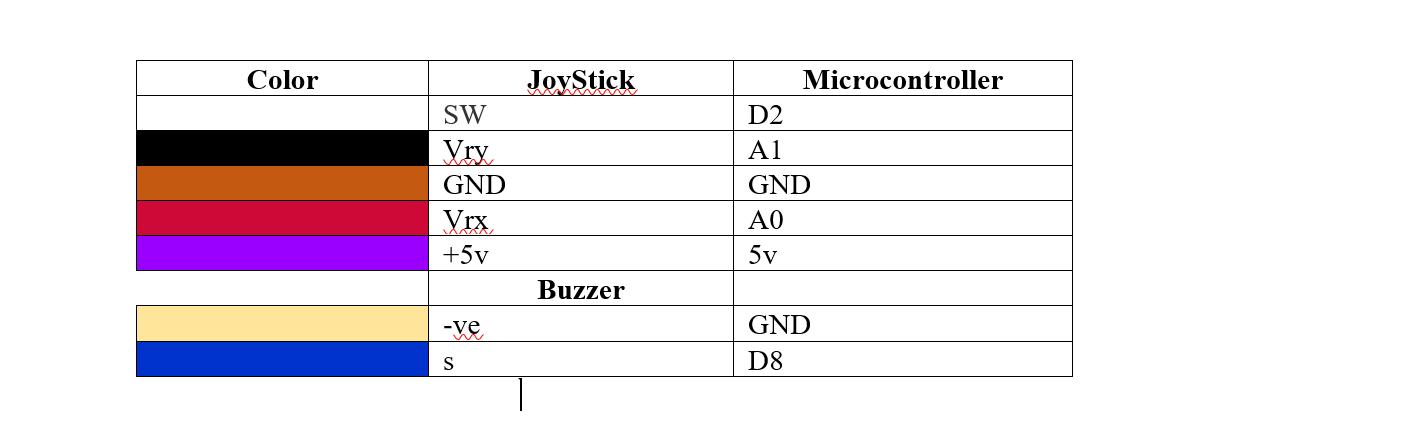
So I have connected a buzzer to a joy stick through the following connection diagram shown on the table:
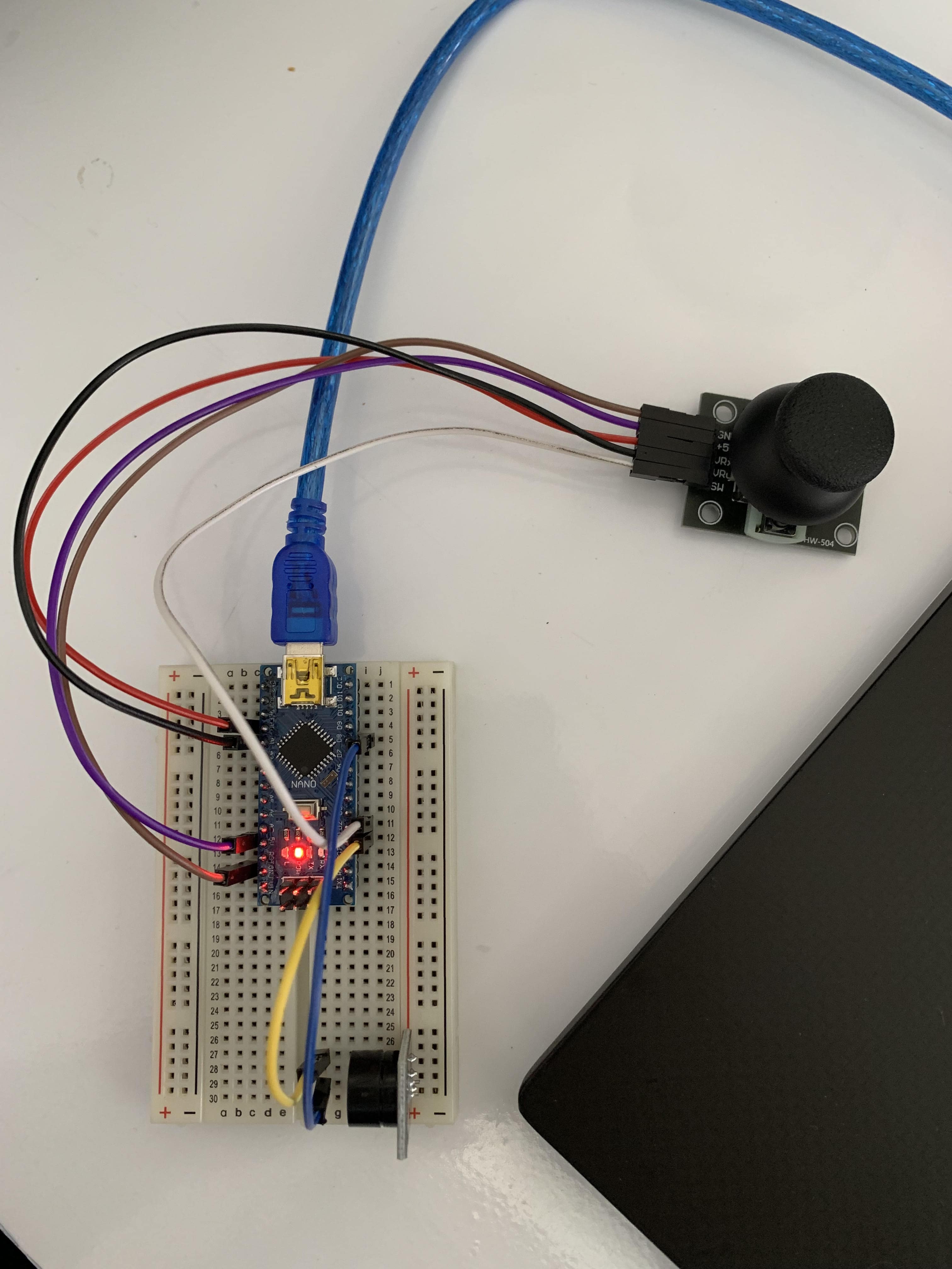
By this the following photo shows the circuit diagram
And the following code is the code I have used in order to do the operation of both devices. This code operates while moving the joystick head to the x-axis only. So it has only one INPUT and OUTPUT.
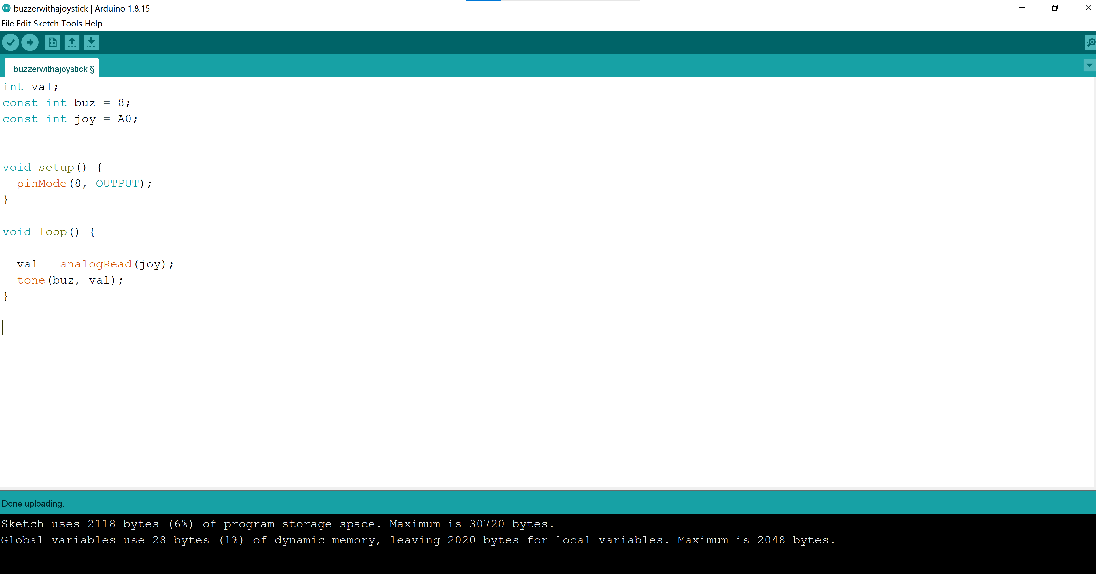
The code is inspired by the code used in the following YouTube video:
By the end this video shows you how it operates
This method was successful, so I have tried to do the other switches as INPUT but I did not get the results this lead me to my third attempt.
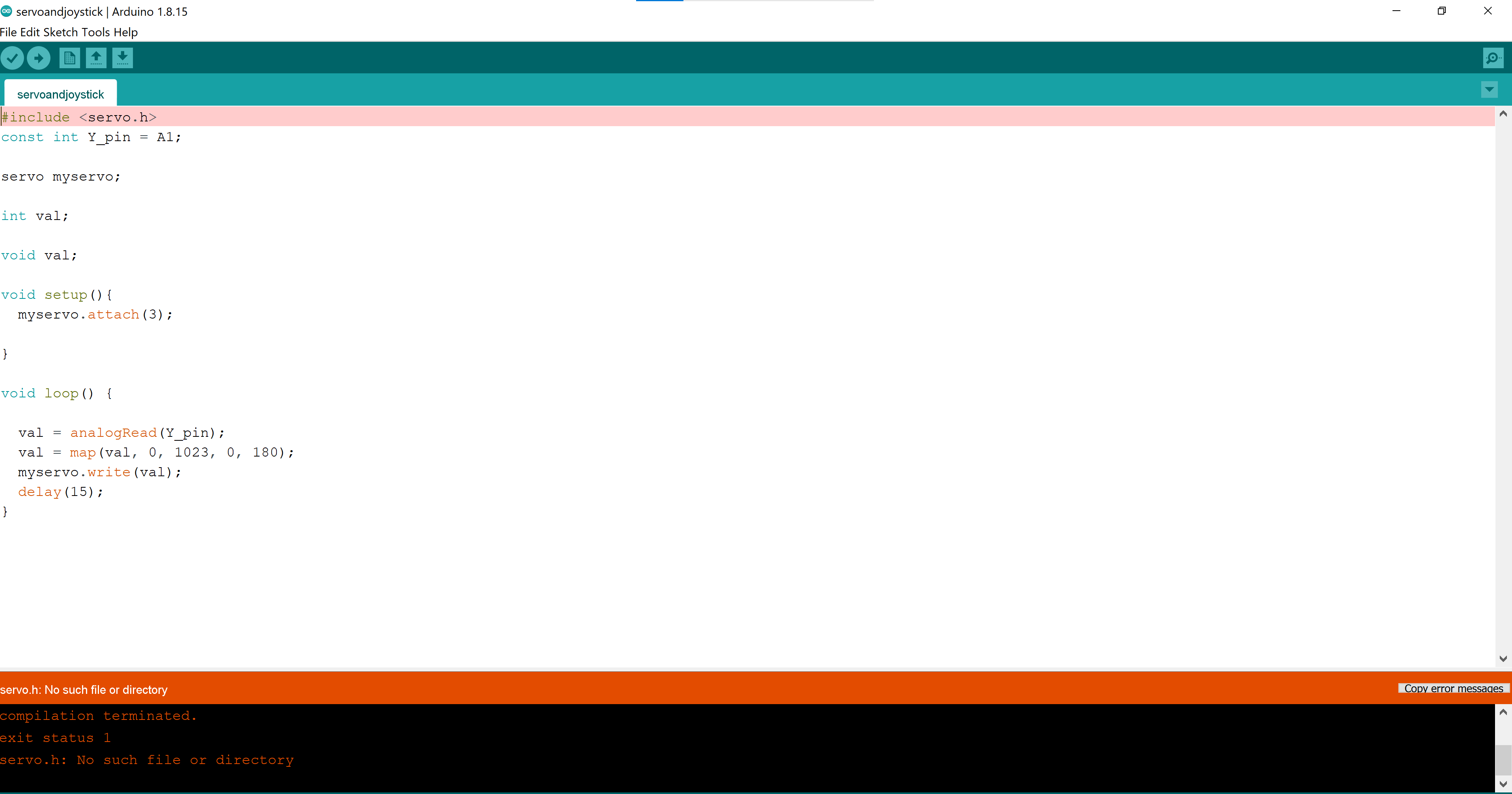
Third attempt
I have tried to do another code to test it which I saw online and got interested which is linked here
So I have changed some of the parameters in order to it to match my connection diagram circuit specifications but it did not work.
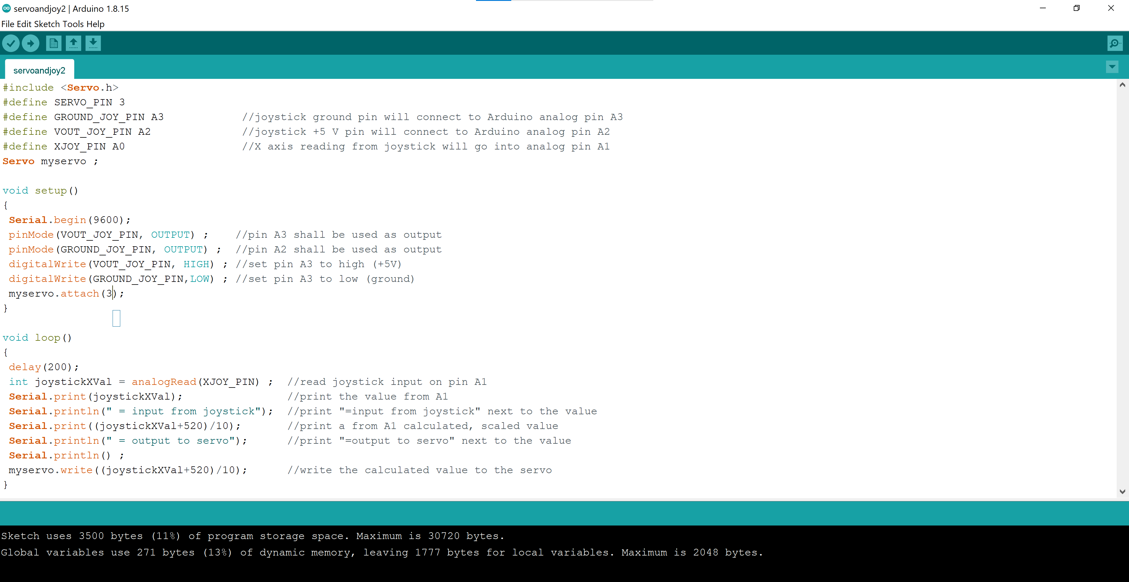
Forth attempt (Servo motor and Joystick)
The code I have followed in order to do this is here where the following photo shows the code written for my specifications in the circuit connection wires.
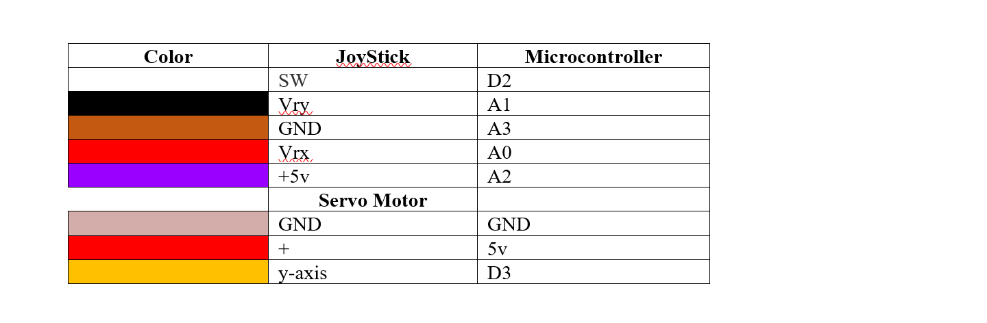
The table below shows the connection of the circuit
 Thus the following picture has the diagram where you can see the wiring in real life.
This Video shows the servo motor and how is connected to the joy stick, the serial monitor on the Arduino program describe the motion on the y-axis only of the joystick.
The following video has an extra idea which is inspiring
But when I have tried to do the exact code it did not work
References
- (1) What is Flame Sensor
- (2) Flame Sensor
- (3) Flame sensor Connection example
- (4) JoyStick